Language selection

Search

Patent 2502016 Summary

Third-party information liability

Some of the information on this Web page has been provided by external sources. The Government of Canada is not responsible for the accuracy, reliability or currency of the information supplied by external sources. Users wishing to rely upon this information should consult directly with the source of the information. Content provided by external sources is not subject to official languages, privacy and accessibility requirements.

Claims and Abstract availability

Any discrepancies in the text and image of the Claims and Abstract are due to differing posting times. Text of the Claims and Abstract are posted:

  • At the time the application is open to public inspection;
  • At the time of issue of the patent (grant).
(12) Patent Application: (11) CA 2502016
(54) English Title: TENSIONING DEVICE FOR DRIVING A TRACTION MECHANISM
(54) French Title: DISPOSITIF DE TENSION POUR ENTRAINEMENT A MECANISME DE TRACTION
Status: Dead
Bibliographic Data
(51) International Patent Classification (IPC):
  • F16H 7/12 (2006.01)
  • F16H 7/08 (2006.01)
(72) Inventors :
  • KONANZ, HOLGER (Germany)
(73) Owners :
  • INA-SCHAEFFLER KG (Germany)
(71) Applicants :
  • INA-SCHAEFFLER KG (Germany)
(74) Agent: MACRAE & CO.
(74) Associate agent:
(45) Issued:
(86) PCT Filing Date: 2003-09-05
(87) Open to Public Inspection: 2004-04-29
Availability of licence: N/A
(25) Language of filing: English

Patent Cooperation Treaty (PCT): Yes
(86) PCT Filing Number: PCT/EP2003/009858
(87) International Publication Number: WO2004/036086
(85) National Entry: 2005-04-08

(30) Application Priority Data:
Application No. Country/Territory Date
102 48 352.3 Germany 2002-10-17

Abstracts

English Abstract


The invention concerns a tensioning device (1) for driving a traction
mechanism, comprising a base part (2) and a pivoting arm (5) connected by a
pivot bearing (6). A twisting spring (11) enables the swivelling roller (8)
placed at the free end of the pivoting arm (5) on the belt (10) to be
supported by friction-type connection. A motion damping system for adjusting
the movement of the pivoting arm (5) includes a friction ring (15).


French Abstract

La présente invention concerne un dispositif de tension (1) pour un entraînement à mécanisme de traction, qui comprend une partie de base (2) et un bras pivotant (5) reliés par un coussinet de pivotement (6). Un ressort de torsion (11) permet de soutenir par liaison de force le galet de roulement (8) placé à l'extrémité libre du bras pivotant (5) sur la courroie (10). Un système amortissant le mouvement de réglage du bras pivotant (5) comprend une bague de frottement (15).

Claims

Note: Claims are shown in the official language in which they were submitted.


Claims

1. A tensioning device for a traction drive by which a traction member, in
particular a belt (10, 40), can be maintained under tension, the tensioning
device (1, 31), comprising:
- a base part (2, 32) which is connected via a pivot bearing (6, 36) to
a pivot arm (5, 35) which has a free end for rotatable arrangement
of a running roller (8, 38) supported on the traction member;
- a spring member, in particular a torsion spring (11, 41), which
realizes a force-fitting support of the running roller (8, 38) on the
traction member and acts upon the pivot arm (5, 35);
- a damping unit placed between the base part (2, 32) and the pivot
arm (5, 35) and configured as a friction bushing (15, 45) having a
conical friction surface and acted upon by an axial force of the
torsion spring (11, 41), for damping an adjusting movement of the
pivot arm(5, 35);
characterized in that the slitted friction bushing (15, 45) is disposed in
surrounding radially spaced-apart relationship to the rotation axis of the
pivot bearing (6, 36) and configured as a wedge ring having an inner
surface (18, 48) and an outer surface (19, 49) which have same conicity,
wherein the friction bushing (15, 45), when installed, engages formfittingly
in a circular ring shaped recess (20, 50) of the associated further
component of the tensioning device (1, 31), wherein contact surfaces (21,
22; 51, 52) of the recess (20, 50) correspond commonly with the inner
surface (18, 48) and the outer surface (19, 49) of the friction bushing (15,
45) for formation of two sonically aligned contact zones (23, 24; 53, 54).


2. Tensioning device according to claim 1, wherein, for formation of the pivot
bearing (6), the pivot arm (5) has a hub (4) which is rotatably supported on
a pin (3) of the base part (2) and the friction bushing (15) is placed axially
between a thrust washer (12) of the base part (2) and the hub (4) of the
pivot arm (5).

3. Tensioning device according to claim 1, whose pivot bearing (36) includes
a bearing pin (34) non-rotatably connected with the pivot arm (35) and
rotatably placed in a bushing (33) of the base part (32), wherein the friction
bushing (25) is arranged axially between the base part (32) and a thrust
washer (42) of the pivot arm (35).

4. Tensioning device according to claim 1, wherein the friction bushing (15,
45) is connected, when installed, to a non-rotatably fixed component and
engages in the recess (20, 50) which is provided in a swingable
component of the tensioning device (1, 31).

5. Tensioning device according to claim 1, wherein the friction bushing (15,
45), secured directly or indirectly on the pivot arm (5, 35) cooperates with
the recess (20, 50) which is formed in a non-rotatable component of the
tensioning device (1, 31).

6. Tensioning device according to claim 1, wherein the friction bushing (15,
45) is securely fixed to a thrust washer (12) non-rotatably connected to the
base part (2).

7. Tensioning device according to claim 1, wherein the inner surface (18, 48)
and the outer surface (19, 49) of the friction bushing (15, 45) are aligned
conically to one another at an angle of <= 35°.

11


8. Tensioning device according to claim 1, comprising a friction bushing (15,
45) of plastic, or the friction bushing (15, 45) is provided with friction
linings
made of plastic.

9. Tensioning device according to claim 1, wherein the damping unit includes
a friction bushing (15, 45) made of organic plastic.

10. Tensioning device according to claim 1, wherein the inner surface (18, 48)
and/or the outer surface (19, 49) of the friction bushing (15, 45) is profiled
or textured.

11. Tensioning device according to claim 1, wherein the comically aligned
contact surfaces (21, 22; 51, 52) of the recess (20, 50), which interact with
the friction bushing (15, 45) are profiled or textured.

12. Tensioning device according to claim 1, wherein lubricant is applied upon
the contact zones (23, 24; 53, 54) of the damping unit.

13. Tensioning device according to claim 1, wherein the damping unit has
lubricant-free contact zones (23, 24; 53, 54).

14. Tensioning device according to one of the claims 4 to 6, comprising a
friction bushing (15, 45) which is formfittingly secured on a component of
the tensioning device (1, 31).

15. Tensioning device according to claim 14, whose friction bushing (15, 45)
includes in addition to a formfitting connection a non-detachable
connection, in particular by gluing or ultrasonic welding.
12
Description

Note: Descriptions are shown in the official language in which they were submitted.


CA 02502016 2005-04-08
TENSIONING DEVICE FOR A TRACTION DRIVE
Field of the invention
The invention relates to a tensioning device by which a traction member, in
particular a belt for a traction drive, can be maintained under tension. The
configuration of the device includes a base part which is connected via a
pivot
bearing to a pivot arm which has a free end for rotatable arrangement of a
running roller supported on the traction member. A spring member,,in
particular a
torsion spring, is provided to realize a force-frtfiing support of the running
roller on
the traction member and acts upon the pivot arm. The tensioning device is
further
provided with a damping unit for damping an adjusting movement of the pivot
arm. The friction bushing has hereby a conical friction surface which
corresponds
to a pertaining further sonically configured contact surface.
Background of the Invention
A tensioning device of the afore-described type is shown in DE 196 47 225. The
configuration of this tensioning device includes a base part which is
restrained
against rotation and has a symmetry axis which defines at the same time the
rotation axis for the pivot arm. The pivot arm has a running roller which is
supported on the traction member in a force fitting manner by the torsion
spring
arranged between the base part and the pivot arm. The damping unit of the
known tensioning device includes a thrust Cone configured as separate base
part
and engaging in a friction cone of the pivot arm in a form-fittirig manner.
The
thrust cone is supported in force-fitting manner on the friction cone by means
of a
compression spring placed between the thrust cone and the base part. This
known damping unit in a tensioning device requires a large installation space
for
realizing a sufficient friction surface between the thrust cone and the
friction
1


CA 02502016 2005-04-08
cone. Furthermore, the number of components increases disadvantageously by
the separate compression spring associated to the thrust cone.
Summary of the Invention
It is an object of the present invention to increase the friction torque of
the
damping unit to obviate the drawrbacks of the known tensioning device, without
enlargement of the existing installation space.
The afore-mentioned problem is solved by a slitted friction bushing disposed
in
surrounding relationship to the rotation axis of the tensioning device and
configured as a wedge ring or double wedge ring. The friction bushing includes
an inner surface as well as an outer surface which have same conicity. ' When
installed, the friction bushing according to the invention engages
formfittingly in a
circular ring shaped recess of the associated further component of the
tensioning
device. The contact surfaces of the circular ring shaped recess correspond
hereby to the conical inner surface and conical outer surface of the friction
bushing, for formation of two sonically aligned contact zones. The friction
bushing
slitted in accordance with the invention can be suited in an optimum way to
the
corresponding contact surfaces of the component which interacts with the
friction
bushing. The friction bushing, configured as wedge ring and forming two
conical
surfaces, effects a wanted rise of the friction torque. The principle of the
damping
unit in accordance with the invention further allows a separation of the
functions
friction generation and sliding support between the base part and the pivot
arm of
the tensioning device. This functional separation has the added advantage that
the system-based wear in the area of the tapered or sonically aligned contact
zones has no impact on the rectangularity, the rectangular arrangement of the
pivot arm in relation to the base part. As a consequence of the disposition of
the
friction bushing according to the invention in radially distanced surrounding
relationship to the rotation axis of the pivot bearing of the tensioning
device, the
2


CA 02502016 2005-04-08
damping unit according to the invention has no impact on the support of the
pivot
arm, whose shape and length is not influenced by the damping unit.
By arranging the friction bushing according to the invention directly or
indirectly
between the base part and the pivot arm, the torsion spring placed between
these components applies an axial force directly upon the friction bushing and
thus upon the conically extending inner surface and outer surface, thereby
having a positive effect on the desired higher friction force. The increased
friction
results in an effective damping of the adjusting movements of the pivot arm.
Further advantageous configurations of the invention are the subject matter of
the dependent claims 2 to 15.
The damping unit according to the invention is applicable for differently
configured tensioning devices having a pivot arm. In tensioning devices having
a
pivot arm with a hub rotatably supported on a pin of the base part for forming
a
pivot bearing, it is possible to place the friction bushing axially between a
flange
of the base part and the hub. (n alternatively designed tensioning devices
having
a pivot bearing formed by a shaft of the pivot arm as well as by a guide bush
connected to the base part, the friction bushing is arranged axially between
the
base part and a flange or thrust washer connected to the pivot arm.
Advantageously, the invention further includes various fixations and
arrangements of the friction disk in the tensioning device. A preferred
arrangement involves the disposition of the friction bushing on a non-
rotatably
fixed component of the tensioning device, with the conically extending inner
surface and outer surface of the friction bushing formfittingly engaging in
the
associated recess which is arranged in a swingable component of the tensioning
device. As an alternative, the invention covers a rigid installation of the
friction
bushing upon the swingable component, with the friction bushing cooperating
3


CA 02502016 2005-04-08
with a recess which is formed in a non-rotatab(y fixed component of the
tensioning device,
The damping unit according to the invention, having a friction bushing with
two
conical surfaces, is preferably provided that the inner surface and the outer
surtaee are aligned at an angle of < 35°. The friction bushing, farming
a double
wedge, effects a significant increase of the friction force and allows the
wanted
separation of the functions friction generation and sliding friction of the
tensioning
device. System-based wear of the friction surfaces of the friction bushing
thus
has no impact on the rectangularity of the moving components of the tensioning
device.
According to a further configuration of the invention, the friction bushing is
made
of plastic. As an alternative, the provision of a two-component friction
bushing is
applicable which has friction linings made of plastic and applied as separate
component on a bushing, a carrier part. A measure to optimize wear of the
friction lining and friction bushing, the invention further includes a
friction bushing
made of glass fiber reinforced plastic or a friction lining of glass fiber
reinforced
plastic.
The damping unit according to the invention is not limited tv the use of the
afore-
stated materials for the friction bushing. For example, the friction bushing
may
also be made of organic plastic or other suitable materials.
According to a further advantageous configuration of the invention, the inner
surface and/or outer surface of the friction bushing is profiled or provided
with a
structure. A suitable profile involves provision of the sonically aligned
surfaces,
the inner surFace and/or outer surface with grooves or indentations that
radiate
out, or creation of a surface with a waffle-like structure. The profiling has
hereby
especially the task to pick up wear based abrasions from the contact zone
4


CA 02502016 2005-04-08
between the inner surface and the outer surface of the friction bushing, on
one
hand, and from the conical recess in the associated component, on the other
hand. The groove profile may hereby advantageously be so configured that the
abrasions shift via the structure or profile, when installed, as a consequence
of
the adjusting movement of a component, i.e. are removed from the contact zone.
This positively affects noise generation.
As an alternative, or in addition to the structured inner surface and outer
surface
of the friction bushing, the invention relates further to a respectively
profiled
contact surface of the circular zing shaped recess engaged by the friction
bushing, when installed.
The damping unit according to the invention is constructed to allow use of the
friction bushing without lubricant or wetted with lubricant. The lubricant,
which
may impact the friction torque of the damping unit, may hereby incorporated in
the damping unit in any manner.
A measure to simplify the assembly involves a formfitting securement of the
friction bushing on a component. This ensures during assembly an unimpeded
placement of the conicaily extending inner surface and outer surface in the
respectively corresponding circular ring shaped recess of the associated
further
component. In addition to a formfitting connection, which for example includes
partially arranged pins or projections for engagement in respective recesses
of
the component to which the friction bushing is securely fixed, it is possible
to
additionally secure the friction bushing by a non-detachable connection, in
particular by gluing or ultrasonic welding.
Brief Description of the Drawings
Exemplified embodiments of ttte invention will now be described in more detail
5


CA 02502016 2005-04-08
with reference to the drawings in which:
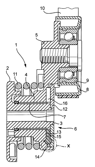
Fig. 1 shows a longitudinal section of a tensioning device provided with a
damping unit according to the invention;
Fig. 2 shows the detail "X" according to Fig. 1 on an enlarged scale;
Fig. 3 shows a longitudinal section of an alternative tensioning device to
Fig. 1;
Fig. 4 shows the detail "Y" on an enlarged scale, with the friction disk
securely fixed to the base part;
Fig.5 shows a fragmentary component drawing of the friction disk
according to Fig. 4.
Detailed Description of the Drawings
Fig. 1 shows the tensioning device 1, comprised of a stationary base part 2
having an axially protruding pin 3. The pin 3 forms together with a hub 4 of a
pivot amp 5 a pivot bearing 6 which includes a sliding bearing bush 7 arranged
in
an installation space bounded radially by the hub 4 and the pin 3. Rotatably
arranged via a roller bearing 9 on a free end of the pivot arm 5 is a running
roller
8 which is supported directly on a belt 10, a traction member, when installed.
A
force-fitting abutment of the running roller 8 on the belt 10 is realized by a
torsion
spring 11 having one Spring end positioned on the base part 2 and the further
spring end positioned on the pivot arm 5 for swinging the pivot arm 5 to a
position
by which the tension force of the belt 10 is increased. The torsion spring 11
further applies an axial force to urge the pivot arm 5 in direction of a
thrust
washer 12 which is secured in fixed rotative engagement to the pin 3. A
friction
6


CA 02502016 2005-04-08
bushing 15 is disposed in an installation space 14 bounded axially by the
thrust
washer 12 and a support surface 13. The friction bushing includes a slit 16
and
has the task to damp the adjusting movement of the pivot arm 5.
Fig. 2 shows an enlarged illustration of the detail "X" according to Fig. 1
and
elucidates the assembly position of the friction bushing 15. The friction
bushing is
provided in direction of the pivot arm 5 with an axially projecting protrusion
17 to
form an inner surface 18 as well as an outer surface 19 which have a same
conicity. The protrusion 17 formfittingly engages a circular ring shaped
recess 20
of the pivot arm 5, with the inner surface 18 as well as the outer surface 19
resting on pertaining contact surfaces 21, 22 of the recess for formation of
two
sonically aligned contact zones 23, 24. When the friction bushing 15 is
installed,
a gap dimension 27 is formed between the support surface 13 and the friction
bushing 15. A defined frictional damping befinreen the friction bushing 15 and
the
pivot arm 5 is realized by securely fixing the friction bushing 15 on the
thrust
washer 12. This is implemented by providing the friction bushing 15 with at
least
one projection 25 which formfittingly engages a bore 26 of the thrust washer
12.
Fig. 3 shows the tensioning device 31, comprised of the base part 32, which
includes in midsection an axial bush 33. Placed in the bush 33 is a bearing
pin 34
of the pivot arm 35, whereby the bush 33 defnes together with the bearing pin
the pivot bearing 36. Disposed in an annular gap, bounded radially by the bush
33 and the bearing pin 34, is the sliding bearing bush 37. A running roller 38
is
provided at the free end of the pivot arm 35 and is rotatably supported by a
roller
bearing 39, whereby the running roller 38 is supported in force-fitting manner
upon the belt 40, when installed. The forced support of the running roller 38
upon
the belt 40 is realized by the torsion spring 41 having a first spring end
positioned
against the base part 32 and a second spring end positioned on the pivot arm
35.
The axial force of the torsion spring 41 is borne by mEens of a thrust washer
42
secured in fixed rotative engagement to the bearing pin 34. The thrust washer
42
7


CA 02502016 2005-04-08
is hereby supported on the friction bushing 45 having a slit 46 and placed in
an
installation space 44 bounded axially by the support surface 43 of the base
part 32 and the thrust washer 42.
Fig. 4 shows the detail "Y" according to Fig. 3, on an enlarged scale, and
elucidates the configuration of the damping unit according to the invention.
The
friction bushing 45 is securely faced to the thrust washer 42 by a projection
55
which protrudes axially from an outer circumference and formfittingly fits in
a
groove 56 of the thrust washer 42, thereby establishing a desired friction
damping between the friction bushing 45 and the support surtace 43 of the base
part 32. The friction bushing 45 is also provided with a slit 46 has a side
which
faces away from the thrust washer 42 and includes an axially projecting
circumferential protrusion 47 having a sonically extending inner surface 48 as
well as a sonically aligned outer surface 49. The protrusion 47 is fitted in
the
recess 50 of the base part 32, with the recess 50 being so sized that the
protrusion 47 does not fully fill the cross sectional profile -of the
protrusion 47 so
as to establish an axial gap dimension 57 between the friction bushing 45 and
the support surface 47 of the ,ease part 32. The protrusion 47 is hereby
supported via the inner surface 48 and the outer surface 49 on the
substantially
complementarily conical contact surfaces 51, 52 which define in concert the
contact zones 53, 54.
Fig. 5 elucidates in particular details of the friction bushing 45. The
surfaces, the
inner surface 48 and the outer surface 49, which extend sonically toward one
another extend at an angle "a" relative to each other. In addition, the outer
surtace 49 is shown here with a structure in form of a longitudinal groove 58
which is provided to pick up wear-based abrasion of the friction bushing 45 or
pertaining contact surface 52, when installed. An alternative measure to allow
expulsion of wear-based abrasion from the contact zones 53, 54, involves the
incorporation of alternating grooves in the inner surface and in the outer
surface.
8


CA 02502016 2005-04-08
Reference Numerals
1 tensioning device 31 tensioning device


2 base part 32 base part


3 pin. 33 bushing


4 hub 34 bearing pin


pivot arm 35 pivot arm


6 pivot bearing 36 pivot bearing


7 sliding bearing bushing37 sliding bearing
bushing


8 running roller 38 running roller


9 roller bearing 39 roller bearing


traction member 40 belt


11 torsion spring 41 torsion spring


12 thrust washer 42 thrust washer


13 support surface 43 support surface


14 installation space 44 installation space


friction bushing 45 friction bushing


16 slit 46 slit


17 protrusion 47 protrusion


18 inner surface 48 inner surface


19 outer surface 49 outer surface


recess 50 recess


21 contact surface 51 contact surface


22 contact surface 52 contact surface


23 contact zone 53 contact zone


24 contact zone 54 contact zone


projection 55 projection


26 bore 56 groove


27 gap dimension 57 gap dimension


28 58 longitudinal groove


29


9

Representative Drawing
A single figure which represents the drawing illustrating the invention.
Administrative Status

For a clearer understanding of the status of the application/patent presented on this page, the site Disclaimer , as well as the definitions for Patent , Administrative Status , Maintenance Fee  and Payment History  should be consulted.

Administrative Status

Title Date
Forecasted Issue Date Unavailable
(86) PCT Filing Date 2003-09-05
(87) PCT Publication Date 2004-04-29
(85) National Entry 2005-04-08
Dead Application 2009-09-08

Abandonment History

Abandonment Date Reason Reinstatement Date
2008-09-05 FAILURE TO PAY APPLICATION MAINTENANCE FEE
2008-09-05 FAILURE TO REQUEST EXAMINATION

Payment History

Fee Type Anniversary Year Due Date Amount Paid Paid Date
Application Fee $400.00 2005-04-08
Registration of a document - section 124 $100.00 2005-07-11
Maintenance Fee - Application - New Act 2 2005-09-06 $100.00 2005-08-17
Maintenance Fee - Application - New Act 3 2006-09-05 $100.00 2006-08-15
Maintenance Fee - Application - New Act 4 2007-09-05 $100.00 2007-08-23
Owners on Record

Note: Records showing the ownership history in alphabetical order.

Current Owners on Record
INA-SCHAEFFLER KG
Past Owners on Record
KONANZ, HOLGER
Past Owners that do not appear in the "Owners on Record" listing will appear in other documentation within the application.
Documents

To view selected files, please enter reCAPTCHA code :


To view images, click a link in the Document Description column. To download the documents, select one or more checkboxes in the first column and then click the "Download Selected in PDF format (Zip Archive)" or the "Download Selected as Single PDF" button.

List of published and non-published patent-specific documents on the CPD .

If you have any difficulty accessing content, you can call the Client Service Centre at 1-866-997-1936 or send them an e-mail at CIPO Client Service Centre.


Document
Description 
Date
(yyyy-mm-dd) 
Number of pages   Size of Image (KB) 
Claims 2005-04-08 3 114
Abstract 2005-04-08 2 79
Drawings 2005-04-08 2 90
Description 2005-04-08 9 421
Representative Drawing 2005-04-08 1 23
Cover Page 2005-07-05 1 42
PCT 2005-04-08 3 121
Assignment 2005-04-08 3 96
Correspondence 2005-06-29 1 25
Assignment 2005-07-11 2 54