Note: Descriptions are shown in the official language in which they were submitted.
CA 02502049 2005-03-22
r t
1~1PPLICA'ThDR I3EVICE ~'C?1'~ DICIIT~D I4AT~R~ALB
Field of the Invention
The present invention relates to applicator devices
for medicated materials and, more particularly, to an applicator
device adapted for depositing medicated materials in a bodily
cavity or passage.
Background of the Invention
Applicators have been in use for delivering medicated
materials (e. g., suppositories, creams and ointments) to bodily
cavities, such as vaginal canals and recta. Conventional
applicators are equipped with barrel members for receiving
medicated materials and plunger members for expelling same from
the barrel members into bodily cavities.
The barrel members of some applicators include loading
ends which are typically equipped with finger-like members or
segments projecting therefrom for releasably attaching
suppositories to the loading ends (see, for instance, U.S.
Patent Nos. 2,754,822: 3,667,465; 3,934,584 4,361,150
5,201,779; 5,404,870; and 5,860,946). The finger-like members
are sized such that, when suppositories are loaded onto the
loading ends, they are enclosed substantially entirely by the
finger-like members.
1
CA 02502049 2005-03-22
~ w
The suppository applicators discussed above have
various disadvantages. For instance, suppositories, when
exposed to moisture, tend to stick to surfaces that are in
contact therewith. In such circumstances, when the applicators
are exposed to relatively high humidity, suppositories loaded
therein tend to stick to the loading ends of the applicators.
Because the suppositories axe enclosed substantially entirely by
the finger-like members, they have a relatively large area of
contact with the loading ends of the applicators . As a result,
when the suppositories stick to the applicators during storage
or use, it becomes difficult to expel same from the applicators.
In addition to the disadvantages discussed above,
conventional applicators are substantially rigid such that they
do not easily conform to natural curves of the bodily cavities
to which they are inserted. As a result, rigid conventional
applicators can cause discomfort to their users.
In the foregoing circumstances, there is a need for an
improved applicator device overcoming the disadvantages and
shortcomings discussed above.
Summary of the Invention
The present invention overcomes the disadvantages and
shortcomings discussed above by providing an improved applicator
device for delivering pharmaceutical products or the like to a
2
CA 02502049 2005-03-22
r
bodily cavity. More particularly, the device includes a barrel
member having a distal end which is equipped with an opening.
The applicator also includes a plurality of petals extending
outwardly from the distal end in a generally axial direction.
The petals cooperate with the opening so as to form a receptacle
for releasably receiving a pharmaceutical product in the distal
end of the barrel member. Eaeh of the petals has a truncated
flexible tip sized and shaped so as to engage a substantially
central portion of the pharmaceutical product such that a large
section of the pharmaceutical product extends outwardly beyond
the petals so as to facilitate the release of the pharmaceutical
product from the receptacle. The device also includes a plunger
member for releasing the pharmaceutical product from the
receptacle. In accordance with the present invention, the
device can be packaged in a package together with the
pharmaceutical product received in the receptacle.
In accordance with an alternate embodiment of the
present invention, a device for delivering a medicated product
into a bodily cavity includes a barrel member having a
dispensing end, a proximal end, which is positioned opposite the
dispensing end, and a bore, which extends through the barrel
member. The bore is sized and shaped so as to receive a
medicated product therein and includes an opening formed in the
dispensing end of the barrel member. The opening is sized and
3
CA 02502049 2005-03-22
r
shaped so as to permit a medicated product received in the bore
to be dispensed therethrough. The applicator is also provided
with a plunger member movably extending through the bore of the
barrel member for dispending a medicated product from the bore
through the .opening. The barrel member includes at least one
substantially flexible section located between the dispending
end and the proximal end such that the barrel member is bendable
about the flexible section.
Brief Description of the Drawings
For a more complete understanding of the present
invention, reference is made to the following detailed
description of the present invention considered in conjunction
with the accompanying drawings, in which:
Figure 1 is an exploded perspective view of a
suppository applicator constructed in accordance with a first
exemplary embodiment of the present invention;
Figure 2 is a perspective view. of the applicator of
Figure 1 in an assembled configuration ready for use;
Figure 3 is a perspective view of the applicator of
Figure 2 packaged in a blister packaging assembly
Figure 4 is an exploded perspective view of the
blister packaging assembly of Figure 3~
4
CA 02502049 2005-03-22
Figure 5 is a perspective view of the applicator of
Figure 2 illustrating the dispensing of a suppository product;
Figures 6 and 7 are side elevational views of the
applicator shown in Figures 1, 2 and 5, illustrating its
operation;
Figure 8 is an exploded perspective view of a
suppository applicator constructed in accordance with a second
exemplary embodiment of the present invention;
Figure 9 is a perspective view of the applicator of
Figure 8 in an assembled configuration ready fox use;
Figure 10 is a perspective view of the applicator of
Figure 9 packaged in a blister packaging assembly;
Figure 11 is an exploded perspective view of the
blister packaging assembly of Figure 10:
Figures 12 and 13 are side eievational views of the
applicator shown in Figures 8 and 9, illustrating its operation;
Figure 14 is an exploded perspective view of an
applicator constructed in accordance with a third embodiment of
the present invention;
Figure 15 is a partially broken-away, side elevational
view of the applicator shown in Figure 14;
Figure 1SA is an enlarged view of a portion of the
applicator shown in Figure 15;
S
CA 02502049 2005-03-22
Figure 16 is a partially broken-away, perspective view
of an applicator constructed in accordance with a fourth
embodiment of the present invention:
Figure 17 is a partially broken-away, perspective view
of an applicator constructed in accordance with a fifth
embodiment of the present invention;
Figure 18 is a partially broken-away, perspective view
of an applicator constructed in accordance with a sixth
embodiment of the present invention
Figure 18A is an enlarged perspective view of a sealed
end of the applicator shown in Figure 18;
Figure 18B is a perspective view of a modified version
of the sealed end of the applicator shown in Figure 18A; and
Figure 19 is a perspective view of an applicator
constructed in accordance with a seventh embodiment of the
present invention.
Detailed Description of the Exemplary Embodiments
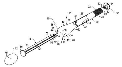
Referring to Figures 1, 2 and 5, there is shown a
suppository applicator 10 constructed in accordance with a first
embodiment of the present invention. More particularly, the
applicator 10 is adapted for use in depositing an oval-shaped
suppository product 12 in a bodily cavity, such as a vaginal
cavity, a rectum, etc. The applicator 10 includes a barrel
6
CA 02502049 2005-03-22
member 14 and a plunger member 16 extending through the barrel
member 14. The barrel member 14 and the plunger member 16 are
made from a suitable material (e. g., thermoplastics,
polyolefins, polyolefin copolymers, modified polyvinyl chloride,
thermoplastic rubber compounds, polyurethanes, etc.) preferably
by a conventional injection molding process. Alternatively, one
or both of the barrel member 14 and the plunger member 16 can be
made by using other conventional processes.
Now referring to Figures 1, 2 and 5-7, the barrel
member 14 is provided with an interior passageway 18 extending
therethrough. The barrel member 14, which has a unitary
construction and an annular wall 20 defining the passageway 18,
is provided with a proximal section 22, a distal section 24 and
an intermediate section 26. The intermediate section 26 is
located between the proximal and distal sections 22, 24. The
proximal section 22 includes an open end 28, as well as a ribbed
surface 30 so as to provide a gripping surface during the use of
the applicator 10. The distal section 24 has a proximal end 32,
which is connected to the intermediate section 26, and a distal
end 34 opposite to the proximal end 32. The distal section 24
has a flaring construction (i.e., the diameter of the proximal
end 32 is smaller than the diameter of the distal end 34) and
has an opening 36 formed therein and communicating with the
passageway 18.
7
CA 02502049 2005-03-22
An annular ring or projection 35 (see Figures 1, 6 and
7) is formed on the intermediate section 26 adjacent to the
proximal end 32 of the distal section 24 for purposes to be
discussed hereinafter. More particularly, the annular ring 35
projects radially inwardly from an inner surface 37 (see Figure
1) of the wall 20 into the passageway 18 of the barrel member
14. The annular ring 35 can be formed integrally with the wall
20 or can be formed as a member discrete and separate from the
wall 20.
The distal section 24 of the applicator 10 is provided
with three flexible, truncated petals 38 (see Figures l, 2 and
5-7) encircling the opening 36 and extending outwardly therefrom
in a direction generally parallel to the longitudinal axis of
the barrel member 14 (referred to hereinafter as "the axial
direction"). The petals 38 cooperate with the opening 36 and
the distal section 24 so as to form a receptacle 40 for
releasably receiving the suppository product 12 therein. Each
of the petals 38 is provided with a generally semi-circular
shape and has a base 42, which is integrally connected to the
distal end 34 of the distal section 24, and a tip 44, which is
located opposite the base 42. Due to its truncated
construction, each of the petals 38 has an axial 'length
sufficient to securely retain the suppository product 12 within
the receptacle 40, but short enough to create a minimal
8
CA 02502049 2005-03-22
frictional resistance to the suppository product 12 during its
dispensing from the receptacle 40. With reference to Figure 6,
the petals 38 are sized and shaped such that, when the
suppository product 12 is received in the receptacle 40, the
tips 44 of the petals 38 engage a substantially central portion
46 of the suppository product 12 (e.g., the tips 44 are adapted
to engage a portion of the suppository product 12 located
slightly outwardly in the axial direction from the central
portion 46 of the suppository product 12). By way of example,
each of the petals 38 can have an axial length which is
substantially equal to one half of the width of the suppository
product 12 measured along its major axis. As a result, a
substantial part of the suppository product 12 (e.g., an
approximately half of the suppository product 12) extends
axially beyond the receptacle 40 to facilitate easy unloading of
the suppository product 12 from the receptacle 40.
Now referring to Figure 1, 6 and 7, each of the petals
38 is provided with a concave interior surface 48 which
corresponds generally to the contour of the central portion 46
of the suppository product 12. More particularly, each of the
petals 38 curves slightly inwardly in a generally radial
direction as it extends from its base 42 to its tip 44 so as to
engage and retain the suppository product 12 in the receptacle
40 (see Figure 6) . In this manner, even if a large part of the
9
CA 02502049 2005-03-22
suppository product 12 extends beyond the tips 44 of the petals
38, the petals 38 cooperate with one another so as to retain the
suppository product 12 in the receptacle 40.
With reference to Figure 6, the barrel member 14 is
also constructed such that the thickness of the wall 20 at the
distal section 24, and more specifically at the tips 44 of the
petals 38, is significantly smaller than the thickness of the
wall 20 at the proximal section 22. In this manner, the petals
38 are provided with a sufficient flexibility and resiliency
such that the petal tips 44 are expandable radially outwardly
and contractible radially inwardly so as to permit easy loading
and unloading of the suppository product 12.
Referring back to Figures 1, 2 and 5-7, the plunger
member 16 includes a ribbed shaft 50 having a proximal end 52
and a distal end 54 and movably received in the passageway 18 of
the barrel member 14. The proximal end 52 of the shaft 50 has
beads 56 (see Figure 1) . A thumb platform 58 is also formed on
the proximal end 52 of the shaft 50 and has a centrally
positioned mounting tab 60. The mounting tab 60 has a female
receptacle opening 62 (see Figure 1) having beads 64 adapted to
engage the beads 56 of the shaft 50 such that the proximal end
52 of the shaft 50 can be snap-fitted into the receptacle
opening 62 of the thumb platform 58. In this manner, the thumb
platform 58 is securely attached to the shaft 50 by an
CA 02502049 2005-03-22
interference fit. A contact platform 66 is integrally formed
with the distal end 54 of the shaft 50. The contact platform 66
is sized and shaped so to be received movably in the receptacle
40 of the distal section 24 of the barrel member 14 for use in
discharging the suppository product 12 from the applicator 10.
In this regard, the contact platform 66 has an oversized shape
(i.e., has a diameter similar or substantially identical to the
width of the suppository product 12 measured along its minor
axis) for purposes to be discussed hereinafter.
With reference to Figures 2 and 5-7, the plunger
member 16 is movable relative to the barrel member 14 in the
axial direction between a retracted position (see Figures 2 and
6), in which the contact platform 66 is positioned adjacent the
proximal end 32 of the distal section 24 of the barrel member
14, and an extended position (see Figure 5 and 7), in which the
contact platform 66 is located axially outwardly from the tips
44 of the petals 38 and hence the receptacle 40. In this
regard, the outer diameter of the thumb platform 58 is greater
than that of the proximal section 22 of the barrel member 14 so
as to prevent the plunger member 16 from moving beyond its
extended position (see Figure 7). Similarly, the outer diameter
of the contact platform 66 is larger than the inner diameter of
the proximal end 32 of the distal section 24 such that the
contact platform 66 engages an interior portion 68 (see Figure
11
CA 02502049 2005-03-22
6) of the distal section 24 located adjacent to the proximal end
32, thereby inhibiting the plunger member 16 from moving beyond
its retracted position. When the plunger member 16 is
positioned in its retracted position, the contact platform 66
abuts an end of the suppository product 12 (see Figure 6) so as
to prevent it from being positioned too tar into the receptacle
40. More particularly, the contact platform 66 ensures that the
suppository product 12 is cradled in the receptacle 40 in a
preferred holding position, in which it is engaged by the distal
section 24 of the barrel member 14 only at the tips 44 of the
petals 38, thereby minimizing the area of contact between the
suppository product 12 and the barrel member 14. In this
regard, the receptacle 40 preferably has a size which is greater
than that of the suppository product 12 such that the entire
interior surface of the receptacle 40, with the exception of the
tips 44 of the petals 38, is out of contact with the suppository
product 12, whereby the suppository product 12 can be released
easily from the receptacle 40.
With reference to Figures 1, 6 and 7, the annular ring
35, which is formed in the passageway 18 of the barrel member
14, is sized and shaped such that the shaft 50 movably extends
through the annular ring 35. The annular ring 35 is adapted to
slidably grip the shaft 50 so as to create a frictional fit
between the barrel member 14 and the plunger member 16. That
12
CA 02502049 2005-03-22
is, the shaft 50 is constantly engaged by the annular ring 35
throughout its movement between the extended and retracted
positions and is thereby held in position by the annular ring
35. In this manner, the shaft 50 and therefore the plunger
member 16 are inhibited from moving freely and causing
interference during the use of the applicator 10. In an
alternate embodiment, the annular ring 35 can be eliminated,
thereby permitting free movement of the plunger member 16.
Referring back to Figure 1, the applicator 10 is
assembled by inserting the shaft 50 into the passageway 18
through the opening 36 of the distal section 24 such that its
proximal end 52 is extended outwardly from the open end 28 of
the barrel member 14. The thumb platform 58 is then attached to
the proximal end 52 of the shaft 50. The suppository product 12
I5 is then inserted into the receptacle 40 of the applicator 10 for
delivery into a bodily cavity.
The applicator 10 can be provided to a user without
the suppository product 12 pre-installed in the receptacle 40.
Alternatively, the applicator 10 can be provided to a user with
the suppository product 12 pre-filled in the receptacle 40.
When provided in its pre-filled form, the applicator 10 can be
packaged in a blister packaging assembly 70 (see Figures 3 and
4). Mare particularly, the blister packaging assembly 70
includes a thermoformed, blister-type PVC (polyvinyl chloride)
13
CA 02502049 2005-03-22
plastic tray 72 for receiving the pre-filled applicator 10.
Alternatively, the tray 72 can be made from any other suitable
materials. The tray 72 includes an outer perimeter rim 74 and a
compartment 76 projecting from the rim 74. The compartment 76
includes an outer cavity section 78 for receiving the distal
section 24 of the barrel member 14, including the suppository
product 12 pre-installed in the receptacle 40. The compartment
76 is also equipped with an intermediate cavity section 80 for
receiving the intermediate section 26 of the barrel member 14.
The intermediate cavity section 80 includes a pair of side
extensions 82 for receiving user's fingers during the removal of
the applicator 10 from the tray 72. An intermediate cavity
section 84 is also connected to the intermediate cavity section
80 for receiving the proximal section 22 of the barrel member
14, while an outer cavity section 86 is connected to the
intermediate cavity section 84 for receiving the thumb platform
58 of the plunger member 16. A peelable lid 88 laminated with
an aluminum foil is attached to the packaging tray 72 in a
conventional manner for sealing the applicator 10 in the
compartment 76.
Tn order to use the pre-filled applicator 10 packaged
in the packaging assembly 70, the applicator 10 is removed from
the packaging assembly 70. The distal section 24 of the
applicator 10, together with the suppository product 12 attached
14
CA 02502049 2005-03-22
thereto, is then inserted into a vaginal canal (not shown) in a
conventional manner. In doing so, the barrel member 14 is
gripped by the user's fingers at the ribbed surface 30 of the
proximal section 22. After properly placing the distal section
24 and the suppository product 12 in the vaginal canal, the
thumb platform 58 of the plunger member 16 is pushed toward the
distal section 24 of the barrel member 14 so as to move the
barrel member 14 from its retracted position (see Figures 2 and
6) to its extended position (see Figures 5 and 7). In this
regard, the applicator i0 can be held and operated by the user
in any conventional manner. For instance, with the proximal
section 22 of the barrel member 14 held by the user's index and
middle fingers, the thumb platform 58 of the plunger member 16
can be pushed by the user's thumb. As the plunger member 16
moves from its retracted position to its extended position (as
indicated by the arrow in Figure 6) , the contact platform 66 of
the plunger member 16 pushes the suppository product 12 out of
the receptacle 40. During the release of the suppository
product 12 from the receptacle 40, the tips 44 of the petals 38
expand in a radially outward direction so as to facilitate the
release of the suppository product 12. In order to ensure the
release of the suppository product 12 from the applicator 10,
the thumb platform 58 is pushed until the plunger member 16 is
positioned in its extended position, in which the contact
CA 02502049 2005-03-22
platform 66 is located axially outwardly from the receptacle 40
(see Figures 5 and 7).
After the release of the suppository product 12 from
the applicator 10 into the vaginal canal, the plunger member 16
is pulled back into its retracted position so as to place the
contact platform 66 within the receptacle 40. In this manner,
during the removal of the applicator 10 from the vaginal cavity,
the contact platform 66 is prevented from coming in contact with
tissue walls of the vaginal cavity and causing injury to same.
The applicator 10 is then cleaned and disinfected for subsequent
use or is discarded.
It should be appreciated that the applicator 10 of the
present invention provides numerous advantages over conventional
applicators. For instance, because the petals 38 of the
applicator la have a truncated construction, they are adapted to
retain the suppository product 12 in the receptacle 40, while
permitting easy release of same from the receptacle 40. As a
result, the suppository product 12 can be released from the
applicator 10 in response to the application of an axial force
that is significantly less than the force required for
conventional applicators. In this manner, even if the
suppository product 12 sticks to the interior surface of the
receptacle 40 during its storage or insertion into a bodily
cavity, it can be released from the receptacle 40 without
16
CA 02502049 2005-03-22
significant difficulty. Because of its ability to release the
suppository product 12 stuck to the receptacle 40, the
applicator 10 can be provided to users in pre-filled and
packaged form.
The oversized contact platform 66 of the plunger
member 16 further ensures the proper dispensing of the
suppository product 12 from the receptacle 40. For instance,
because of its large size, the contact platform 66 tends to
apply an axial force evenly to the suppository product 12,
thereby minimizing distortion of the suppository product 12
during its release from the receptacle 40. Moreover, the
contact platform 66 functions to strip the suppository product
12 off the interior surface of the receptacle 40 if there is
excess friction or sticking between the suppository product 12
and the barrel member 14. In addition, because the suppository
product 12 is mounted to the flaring distal section 24, the
remaining sections of the barrel member 14 (i.e., the
intermediate and proximal sections 26, 22) can be made
relatively slender.
It should be noted that the applicator 10 of the
present invention can have numerous modifications and
variations. For instance, the applicator 10 can be provided
with a different number of petals 38. Moreover, although the
present invention is especially suitable for use in delivering
17
CA 02502049 2005-03-22
suppository products to vaginal canals or cavities, it can be
used to dispense suppository products or other pharmacological
products in other body cavities such as a rectum. Further, the
applicator 10 can be modified to accommodate suppository
products having different geometrical shapes. In addition, the
petals 38 can be provided with different shapes arid lengths.
The applicator 10 can also be packaged in different types of
packages.
Figures 8-19 depict additional exemplary embodiments
of the present invention. Elements illustrated in Figures 8-13,
Figures 14-15A, Figure 16, Figure 17, Figures 18-18B and Figure
19, which correspond to the elements described above with
reference to Figures 1-7, have been designated by corresponding
reference numbers increased by one hundred, two hundred, three
hundred, four hundred, five hundred and six hundred,
respectively. Unless otherwise stated or illustrated, the
exemplary embodiments of Figures 14-19 are constructed, used and
operated in the same basic manner as the exemplary embodiment
shown in Figures 1-7.
With reference to Figures 8, 9, 12 and 13, there is
shown a suppository applicator 110 constructed in accordance
with the second embodiment of the present invention. The
applicator 110, which is adapted for use in delivering an oval-
shaped suppository product 112 to a bodily cavity (e.g., a
18
CA 02502049 2005-03-22
vaginal orifice), includes a barrel member 114 having an open
proximal end 128 and an open distal end 134. Unlike the barrel
member 14 of the embodiment of Figures 1-7, the entire barrel
member 114 is substantially cylindrical in shape and is slightly
tapered as it extends from the proximal end 128 to the distal
end 134 ( i . a . , the diameter of the proximal end 128 is slightly
greater than that of the distal end 134). As a result, the
distal end 134 of the barrel member 114 is not flared. The
barrel member 114 includes an interior passageway 118 extending
between the proximal and distal ends 128, 134. A perimeter rim
wall 190 is formed at the proximal end 128, while an annular
retaining rib 192 is formed in the passageway 118 adjacent the
proximal end 128. Flexible, truncated petals 138 are also
formed at the distal end 134 of the barrel member 114. The
petals 138 cooperate with one another so as to define a
receptacle 140 for receiving the suppository product 112.
Still referring to Figures 8, 9, 12 and 13, the
applicator 110 also includes a plunger member 116 having a
single-piece construction. More particularly, the plunger
member 116 includes a ribbed shaft 150, a proximal end 152 and a
distal end 154. A thumb platform 158 is formed at the proximal
end 152 for engagement with the rim wall 190 of the barrel
member 114, while a contact platform 166 is formed at the distal
end 154. The contact platform 166 has a diameter smaller than
19
CA 02502049 2005-03-22
the inner diameter of the retaining rib 192 of the barrel member
114 such that it can be inserted into the passageway 118. The
diameter of the contact platform 166 is also larger than an
inner diameter D (see Figure 8) of the receptacle 140 defined by
the petals 138 such that, when the contact platform 166 is
positioned in the receptacle 140, it comes in contact with the
petals 138 and causes same to flex radially outwardly (see
Figure 13), thereby facilitating the release of the suppository
product 112 from the receptacle 140. A stopping platform 194 is
formed on the shaft 150 adjacent to the proximal end 152 of the
shaft 150. The stopping platform 194 has a diameter slightly
larger than the inner diameter of the retaining rib 192 of the
barrel member 114 for purposes to be discussed hereinafter. In
this regard, the stopping platform 194 is slightly flexible such
that it can be inserted into the passageway 118 from the
proximal end 128 of the barrel member 114 and positioned between
the retaining rib 192 and the distal end 134.
The plunger member 116 is movably mounted in the
passageway 118 of the barrel member 114. As a result, the
plunger member 116 is movable relative to the barrel member 114
between a retracted position (see Figure 12), in which the
contact platform 166 is located remote from the petals 138, and
an extended position, in which the contact platform 166 is in
contact with the petals 138 (see Figure 13). In this regard,
CA 02502049 2005-03-22
the retaining rib 192 of the barrel member 114 is engageable
with the stopping platform 194 of the plunger member 116 so as
to inhibit the plunger member 116 from moving beyond its
retracted position. Similarly, the rim wall 190 of the barrel
member 114 is adapted to engage the thumb platform 158 of the
plunger member 116 for the purpose of inhibiting it from moving
beyond its extended position.
With reference to Figures 10 and 11, a blister
packaging assembly 170 is provided for packaging the applicator
110 pre-filled with the suppository product 112. More
particularly, the packaging assembly 170 has a construction
basically identical to that of the blister packaging assembly 70
of the embodiment shown in Figures 1-7. For instance, the
packaging assembly 170 has a tray 172 for receiving the pre-
filled applicator 110 and a peelable lid 188 attached to the
tray 172.
Figures 14-15A illustrate an applicator 210
constructed in accordance with a third embodiment of the present
invention for delivering suppositories into bodily cavities,
such as vaginal cavities or recta. Unless stated otherwise, the
applicator 210 has a construction and operation basically
identical to the construction and operation of the applicator 10
of the embodiment shown in Figures 1-7. More particularly, the
applicator 210 includes a barrel member 214 having a proximal
21
CA 02502049 2005-03-22
section 222, a distal section 224 and an intermediate section
226. More particularly, the proximal section 222 has an open
end 228, while the distal section 224 has an open end 234 and
flexible, truncated petals 238. An interior passageway or bore
218 extends through the barrel member 214 from the open end 228
of the proximal section 222 to the open end 234 of the distal
section 224. An annular ring 235 also projects from an interior
wall of the barrel member 214 into the passageway 218.
Referring to Figures 14 and 15, the barrel member 214
is made, in its entirety (including the proximal, distal and
intermediate sections 222, 224, 226), from a substantially
flexible material such that it is readily bendable or deformable
so as to conform to an interior wall and/or contour of a bodily
cavity when inserted therein. More particularly, while the
barrel member 214 can be made from any flexible ar elastic
materials, thermoplastic elastomers, such as styrene-ethylene-
butylene copolymers, flexible polyvinyl chloride modified with
plasticizers, ultra-low density polyethylene and silicone are
especially suitable for use in making the barrel member 214.
Various durometer can be used to achieve the desired degree of
flexibility of the barrel member 214. The barrel member 214 can
also be made from a rigid or semi-rigid material (e.g., low
density polyethylene) and be constructed with a substantially
thin wall such that it is provided with a high degree of
22
CA 02502049 2005-03-22
flexibility. Any conventional processes can be utilized to make
the barrel member 114. For instance, the barrel member 114 can
be injection-molded or extruded from a flexible material.
Still referring to Figures 14 and 15, a plunger member
216 movably extends through the passageway 218 of the barrel
member 214. The plunger member 216 includes a ribbed shaft 250
and a thumb platform 258 which are monolithically formed with
one another. Referring to Figures 15 and 15A, the shaft 250 has
a tapered distal end 254, while a disc 266 is attached to the
distal end 254 of the shaft 250. More particularly, the disc
266 has a size smaller than the diameter of the passageway 218
or the inner diameter of the annular ring 235 of the barrel
member 214 such that it can pass through the passageway 218 of
the distal, proximal and intermediate sections 222, 224, 226 of
the barrel member 214. In this manner, the plunger member 216,
which has a monolithic construction, can be inserted into the
barrel member 214 from its proximal section 222. As a result,
the plunger member 216 can be assembled with the barrel member
214 in a single step (i.e., the step for attaching the thumb
platform 258 to the shaft 250 is omitted , thereby facilitating
the assembly of the applicator 210. The disc 256 is also sized
and shaped such that it can engage and expel a suppository
loaded in the applicator 210 without puncturing same.
23
CA 02502049 2005-03-22
Like the plunger member 16 of the embodiment shown in
Figures 1-7, the shaft 250 is adapted to frictionally engage the
annular ring 235 such that it is slidably griped by same to
create a frictional fit between the barrel member 214 and the
plunger member 216. The plunger member 216 is also provided
with a disc 294 mounted to the shaft 250. The disc 294 is
positioned and is sized and shaped such that it functions as the
stopping platform 194 of the embodiment illustrated in Figures
8-13. More particularly, the disc 294 has a diameter slightly
larger than the inner diameter of the annular ring 235 of the
barrel member 214. As a result, when the plunger member 216 is
properly inserted into the passageway 218 of the barrel member
214, the disc 294 is engageable with the annular ring 235 so as
to inhibit the plunger member 216 from moving beyond its
retracted position (see Figure 15A) and hence retains the
plunger member 216 assembled with the barrel member 214.
Like the barrel member 214, the plunger member 216 can
be from a similar flexible material in a conventional manner
such that it is bendable or deformable together with the barrel
member 214 when the applicator 210 is inserted into a vaginal
cavity. Alternatively, the plunger member 216 can be made from
a conventional rigid or semi-rigid material (e. g., semi-rigid
thermoplastic material, such as polyethylene or plastic).
Because of its ribbed shaft 250, the barrel member 216 is
24
CA 02502049 2005-03-22
relatively flexible even if it is made from a rigid or semi-
rigid material. In such circumstances, the flexible barrel
member 214 assembled with the relatively rigid plunger member
216 can provide the applicator 210 with flexibility sufficient
for its intended use and purpose.
The applicator 210 is used in the same basic manner as
the applicator 10 of the embodiment shown in Figures 1-7. The
applicator 210 normally assumes a straight or linear shape (as
indicated by the broken line representation of the applicator
210 in Figure 15). When the applicator 210 is inserted into a
bodily cavity, such as a vaginal canal, because of its
flexibility, it can bend freely and/or readily (as indicated by
the solid line representation of the applicator 210 in Figure
15) so as to conform in shape to natural curves and other
possible obstructions in the vaginal canal, thereby
accommodating variations in anatomy and hence providing enhanced
conform to the user. Due to its flexibility, the applicator 210
also allows the user to dispense a suppository in positions
other than the conventionally recommended horizontal
"missionary" position (e. g., in a standing or squatting position
with the user's knees slightly bent). When the applicator 210
is removed from the vaginal cavity, it returns to its normally
straight shape.
CA 02502049 2005-03-22
Besides the advantages discussed above, the applicator
210 has numerous additional advantages. For instance, because
the applicator 210 is made from a flexible material, it provides
a soft feel to the user. Moreover, because the truncated petals
238 are made from a flexible material, they open easily upon
loading a suppository into the applicator 210 and upon
dispensing same from the applicator 210.
The applicator 210 can have numerous modifications and
variations. For instance, the barrel member 214 and/or the
plunger member 216 can be constructed such that certain portions
are flexible, while the remaining portions are rigid. By way of
example, the distal section 224 of the barrel member 214,
including the petals 238 which define a suppository receptacle,
can be made from a rigid material, such as polyethylene, while
i5 the rest of the barrel member 214 (i.e., the proximal and
intermediate sections 222, 226) can be separately extruded or
injection-molded from a flexible material. The relatively rigid
distal section 224 can then be attached to the flexible
intermediate section 226 to form the barrel member 214. More
particularly, the distal section 224 can be provided with a
cylindrically shaped projection which can be friction-fitted
into or onto the intermediate section 226. A rigid flange
(having a construction similar to the construction of the flange
190 of the embodiment shown in Figures 8-13) can also be formed
26
CA 02502049 2005-03-22
separately and be attached to the open end 228 of the proximal
section 222 of the barrel member 214 (e.g., the rigid flange can
be provided with a cylindrically shaped projection which can be
friction-fitted into or onto the open end 228 of the barrel
member 214).
Figure 16 shows an applicator 310 constructed in
accordance with a fourth embodiment of the present invention.
Unless stated or illustrated otherwise, the applicator 310 has a
construction and operation basically identical to the applicator
210 of the embodiment shown in Figures 14-15A. The applicator
310 includes a tube or barrel member 314 which is made from a
flexible material. Unlike the barrel member 214 of the
embodiment of Figures 14-15A, the barrel member 314 is not
provided with any petals, but includes an open end 334 for
receiving suppositories or other medicated solid or non-solid
materials (e. g., creams and ointments).
The applicator 310 also includes a plunger member 316
having a shaft 350 which is equipped with a ribbed section 350a
and a round rod section 350b. The plunger member 316 also has a
disc 366 mounted to an end of the round rod section 350b for
expelling the materials loaded in the open end 334 of the barrel
member 314, and a pair of discs 394a, 394b. The disc 394a is
mounted on the ribbed section 350a, while the disc 394b is
mounted to the plunger member 316 at the interface between the
27
CA 02502049 2005-03-22
ribbed and round rod sections 350a, 350b. The discs 394a, 394b
are adapted to be inserted into the passageway of the barrel
member 314 and engage the inner cylindrical surface of the
barrel member 314 for providing a relatively loose friction fit
between the barrel member 314 and the plunger member 316. The
plunger member 316, which can be made from a flexible material
or a rigid or semi-rigid material, has a thumb platform 358.
Alternatively, the platform 358 can be replaced with other types
of mechanisms, such as a ring attached to the plunger member 316
for accommodating or receiving a person's thumb or finger.
The applicator 310 normally assumes a linear or
straight shape (as indicated by the broken line representation
of the applicator 310 in Figure 16). Because the barrel member
314 and/or the plunger member 316 are flexible, the applicator
310 is adapted to readily bend or deform (as indicated by the
solid line representation of the applicator 310 in Figure 16) so
as to conform to the natural anatomy or contour of a bodily
cavity into which the applicator 310 is inserted.
Figure 17 illustrates an applicator 410 constructed in
accordance with a fifth embodiment of the present invention for
dispensing medicated solid materials (e. g., suppositories)
and/or medicated non-solid materials (e.g., creams and
ointments). More particularly, the applicator 410 includes a
tube or barrel member 414 having a pair of rigid or semi-rigid
28
CA 02502049 2005-03-22
end sections 422, 424 and a bellow section 495 mounted between
the end sections 422, 424. The bellow section 495 has a
plurality of bellows 495a made from a rigid material, but formed
with a relatively thin wall, such that the barrel member 414 is
bendable about the bellow section 495. The bellow section 495
can be located in any position in the barrel member 414 where
shape change is desired. More than one bellow sections can also
be provided in the barrel member 414.
Now referring to Figure 18, there is shown an
applicator 510 constructed in accordance with a sixth embodiment
of the present invention for dispensing medicated non-solid
materials, such as creams or ointments. More particularly, the
applicator 5i0 includes a tube or barrel member 514 made from a
flexible material such that the barrel member 514 is readily
deformable from a normally straight shape to a bent shape. The
barrel member 514 has a pair of ends 528, 534 and a passageway
518 extending therebetween. A peel-off foil 596 (see also
Figure 18A) is attached to the end 534 of the barrel member 514
and seals same so as to contain non-solid medicated materials
pre-filled in the passageway 518. The foil 596 can be peeled
off from the barrel member 514 prior to the insertion of the
applicator 510 into a vaginal cavity. Alternatively, other
types of closure members can be used for sealing the end 534 of
the barrel member 514. For instance, a twist-off cap or tip
29
CA 02502049 2005-03-22
596a (see Figure 1$B) can be removably attached to the end 534
of the barrel member 514.
The applicator 510 is also provided with a plunger
member 516 having a disc 566. More particularly, the disc 566
forms an air or liquid-tight seal with the interior wall of the
barrel member 514 so as to contain medicated creams or ointments
pre-filled in the passageway 518 and to dispense same from the
barrel member 514 when the plunger member 516 is moved from its
retracted position to its extended position.
Figure 19 shows an applicator 610 constructed in
accordance with a seventh embodiment of the present invention
for dispensing medicated non-solid materials into a bodily
cavity. More particularly, the applicator 610 includes a barrel
member 614 having a distal section 624 and a proximal section
622 that are securely attached to one another. The distal
section 624 is made, in its entirety, from a flexible material,
while the proximal section 622 is made, in its entirety, from a
rigid or semi-rigid material. The proximal section 622 has a
distal end 697 inserted into the distal section 624 and secured
thereto by a friction or interference fit. Alternatively, the
distal end 697 of the proximal section 622 can be permanently
attached to the distal section 624 by other mechanisms (e. g.,
bonding or gluing). The distal section 624 has a slightly
angled, tapered tip 698 which is configured so as to reduce
CA 02502049 2005-03-22
friction and/or resistance against the vaginal tissue of a
vaginal cavity, thereby facilitating the insertion of the
applicator 610 into the vaginal cavity and hence promoting
additional comfort to the user. The applicator 610 is also
equipped with a plunger member 616, which can have a one-piece
or multiple-piece construction.
It will be understood that the embodiments described
herein are merely exemplary and that a person skilled in the art
may make many variations and modifications without departing
from the spirit and scope of the invention. All such variations
and modifications, including those discussed above, are intended
to be included within the scope of the invention as defined by
the appended claims.
31