Note: Descriptions are shown in the official language in which they were submitted.
CA 02502777 2005-03-31
AUTOMATIC SLACK ADJUSTER WITH SPRING RELEASE SPINDLE
FIELD OF THE INVENTION
[0001] The present invention relates generally to automatic slack adjusters
for brake
operating systems, and more specifically, to an improved automatic slack
adjuster including
means for disengaging the clutch assembly of a slack adjuster to reduce
premature wear.
BACKGROUND OF THE INVENTION
[0002] It is known to provide an automatic slack adjuster for connecting a
brake operator
to a cam shaft of a vehicle brake system. Such types of automatic slack
adjuster are generally
to described in U.S. Patent No. 5,350,043 (Crewson et al.), U.S. Patent No.
5,762,165 (Crewson)
and U.S. Patent No. 6,450,302 (Lyons), which patents are incorporated by
reference herein.
[0003] When the aforementioned automatic slack adjusters are installed on a
braking
system, the initial rotatable position of the cam shaft relative to the
housing is usually adjusted in
order to ensure proper operation of the braking system. Such adjustment is
typically performed
by rotating a free end of the worm shaft of the automatic slack adjuster with
a wrench or like
tool. A problem associated with adjusting an automatic slack adjuster in this
manner is that the
devices typically comprise a one-way clutch assembly. The one-way clutch
assemblies usually
comprise ratchet teeth disposed on rotor and/or coupling components that
maintain engagement
with one another by means of bias provided by a compression spring.
Consequently, it can be
2o difficult to rotate the free end of the worm shaft because of the high
amount of force exerted by
the compression spring, which acts on the clutch assembly, i.e., the force
applied to the clutch
assembly by the spring must be overcome to rotate the free end of the worm
shaft. More
21389040.1
1
0
CA 02502777 2005-03-31
importantly, however, is the fact that the high amount of force exerted on the
clutch assembly
causes the ratchet teeth of the clutch assembly to grind against one another
when the free end of
the worm gear is rotated. Thus, adjustment in this manner results in excessive
wear of the ratchet
teeth, which ultimately results in the premature wear of the clutch assembly,
which thereby
reduces the lifespan of the slack adjuster.
[0004] What is needed then is an improved automatic slack adjuster that is
easily and
readily adjusted and which prevents premature wear of the clutch assembly.
SUMMARY OF THE INVENTION
[0005] The present invention broadly comprises an automatic slack adjuster
having a
1o disengaging assembly for disengaging the clutch assembly of such device
such that a free end of
a worm shaft may be freely rotated for adjustment. In a preferred embodiment,
the clutch
assembly is one-way and formed from ratchet teeth of a rotor and/or a
coupling. In a preferred
embodiment, the disengaging assembly generally comprises a manually actuated
pin that
separates the rotor and the coupling from one another such that the free end
of a worm shaft of
the automatic slack adjuster may be freely rotated. In a preferred embodiment
the pin is spring
biased.
[0006] It is, therefore, an object of the invention to provide an automatic
slack adjuster
that is readily and easily adjustable.
[0007] It is another object of the invention to provide an automatic slack
adjuster
2o configured to reduce the wear of clutch assembly components when the
automatic slack adjuster
is adjusted.
21389040.1
2
CA 02502777 2005-03-31
[0008] It is, still yet, another object of the invention to provide manually
operable means
for disengaging clutch assembly of an automatic slack adjuster such that a
free end of a worm
shaft may be freely rotated.
BRIEF DESCRIPTION OF THE DRAWINGS
[0009] The nature and mode of operation of the present invention will now be
more fully
described in the following detailed description of the invention in view of
the accompanying
drawing figures, in which:
Figure 1 is a side elevation view of an automatic slack adjuster according to
the
present invention connected to a brake operator of a braking system;
io Figure 2 is an enlarged fragmentary sectional view of an automatic slack
adjuster
according to the present invention with a portion of its housing removed,
which illustrates the
disengaging assembly of the present invention in the "rest" position;
Figure 3 is an enlarged fragmentary sectional view of an automatic slack
adjuster
according to the present invention with a portion of its housing removed,
which illustrates the
disengaging assembly of the present invention in the "actuated" position;
Figure 4 is a sectional view, taken generally along line 4-4 of Figure 2,
which
illustrates the disengaging assembly of the present invention in the "rest"
position;
Figure 5 is a sectional view, taken generally along line 5-5 of Figure 3,
which
illustrates the disengaging assembly of the present invention in the
"actuated" position; and,
2o Figure 6 is a top fragmentary view of an automatic slack adjuster according
to the
present invention illustrating the disengaging assembly in the "rest"
position.
21389040.1
3
CA 02502777 2005-03-31
DETAILED DESCRIPTION OF THE INVENTION
[0010] At the outset, it should be appreciated that like drawing numbers on
different
drawing views identify identical structural elements of the invention. It
should also be
appreciated that while the present invention is described with respect to what
is presently
considered to be the preferred embodiments, the invention is not limited to
the specific
embodiments disclosed herein.
[0011] Referring now to the figures, as shown in Figure 1 automatic slack
adjuster
according to the present invention is generally designated by reference
numeral 10 and is shown
as being connected to an operator shaft 12 of a known brake operating system
via an operator
to shaft mounted clevis 14 and pivot pin 16 and to a cam shaft 18 of a known
vehicle brake system.
In this figure it is seen that the outer structures of slack adjuster 10
generally include an elongated
housing 20 comprising a first bore adjacent one end for receiving pivot pin 16
and a second bore
adjacent an opposite end for rotatably supporting a worm gear 22. Worm gear 22
is suitably
keyed to cam shaft 18 for rotation about first axis 26. Slack adjuster 10 is
also connected to
clevis 14 via link 28, which is slidably supported by housing 20 and has a
protruding end
pivotally connected to the clevis by a pivot pin 30.
[0012] Referring now to Figures 2-6, while several of the interior structures
of a slack
adjuster according to the present invention are described in U.S. Patent Nos.
5,350,043, U.S.
Patent No. 5,762,165, and U.S. Patent No. 6,450,302, a recitation of such
structures and their
operation is provided for a clear understanding of the invention.
21389040.1
4
CA 02502777 2005-03-31
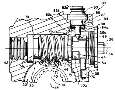
[0013] Interior structures of automatic slack adjuster 10 generally comprise
worm shaft
32, first compression spring 42, rotor 44, coupling 46, second compression
spring 52, member
68, and spring release spindle 80.
[0014] Worm shaft 32 generally comprises first end 36 and second end 38 and is
arranged
for rotational and lateral movement about and along second axis 34. Worm 40 is
disposed
intermediate the first and second ends and is arranged to engage worm gear 22.
First
compression spring 42 is provided for engagement with first end 36 of worm
shaft 32 and tends
to oppose the lateral movement of worm shaft 32 in a direction toward the
first end. Second end
38 of worm shaft 32 freely rotatably mounts rotor 44 and coupling 46 via a
bearing sleeve (not
1o shown). Rotor 44 is coupled to coupling 46 by a suitable one-way clutch 50,
such as may be
defined by ratchet teeth 50a and SOb arranged on facing end surfaces of the
rotor and coupling,
respectively. A second compression spring 52 is arranged between the rotor and
end plug 54 for
biasing the teeth of rotor 44 into engagement with the teeth of coupling 46.
Teeth 50a and 50b
are shaped and arranged to permit coupling of the rotor and coupling when
rotor 44 is rotated in a
first direction, e.g., clockwise when viewed along axis 34 from second end 38,
and permits
uncoupling of the rotor when it is rotated in a second direction, e.g.,
counter-clockwise when
viewed along axis 34 from second end 38.
[0015] Coupling 46 is also releasably connected, or coupled, for rotation with
worm shaft
32 by a slip means (not shown), which may be defined by shallow grooves and
teeth arranged on
2o facing frusto-conical surfaces of coupling 46 and worm 40. Thus,
compression spring 42 tends
to bias worm shaft 32 in the direction of second end 38 such that the grooves
and teeth of the slip
21389040.1
5
CA 02502777 2005-03-31
means engage and connect coupling 46 for rotation with the worm shaft.
Coupling 46 is also
preferably formed with a radially outwardly extending abutment or motion
limiting flange 46a.
[0016] As illustrated more clearly in Figures 4 and 5, rotor 44 is movably
coupled to link
28 by providing the rotor with a radially outwardly projecting lug 60 arranged
to be loosely
received within a recess 62 of the link. Rotor 44 is also provided with
radially outwardly
projecting first and second abutments 64 and 66, respectively, which are
arranged for operable
engagement with member 68 supported for reciprocating movement within a recess
70 defined
by housing 20 under the control of a return spring (not shown), which is
preferably in the form of
a coil type compression spring. Abutment 66, preferably, includes beveled
portion 66a, whose
1o purpose is explained in more detail below. Preferably, member 68 is in the
form of a
cylindrically shaped pin having a side surface, which defines a first abutment
surface 68a
disposed in alignment with the direction of its reciprocating movement, and
oppositely facing
end surfaces, which define second and third abutment surfaces 68b and 68c,
respectively, spaced
apart in such direction of movement. First abutment surface 68a is arranged to
be engaged by
first abutment 64 to define the reference position of rotor 44 shown in Figure
4, second abutment
surface 68b is arranged for engagement by second abutment 66, and third
abutment surface 68c is
arranged for engagement by a return spring (not shown).
[0017] Spring release spindle 80 is provided for manually separating rotor 44
and
coupling 46, for example, during installation, removal and/or troubleshooting
of the stroke
2o indicator in order to minimize clutch assembly wear. Spring release spindle
80 generally
includes pin 82, counter-bore hole 84, annular retaining ring 86, spring 88
and boot 90. Pin 82 is
21389040.1
6
CA 02502777 2005-03-31
configured for slidable movement within counter-bore hole 84, which extends
from the exterior
of housing 20 to the inner cavity of the stroke indicator wherein rotor 44 and
coupling 46 are
housed. Pin 82 comprises button end 82a which protrudes from housing 20 under
bias of spring
88, flange portion 82b for retaining the spring and pin within the counter-
bore hole, and tapered
end 82c for slidably communicating with beveled portion 66a of second abutment
66 of rotor 44.
Annular retaining ring 86 is configured to retain pin 82 within counter-bore
hole 84 and,
preferably, threadably mates with the counter-bore hole. The orifice disposed
within the annular
retaining ring is sized to allow the button end of the pin to pass
therethrough and prevent the
flange portion of the pin to pass. Spring 88 is disposed between the lower
side of flange portion
82b and abutment wall 84a of the counter-bore hole to bias pin 82 such that
the button portion
82a protrudes from housing. Boot 90 is, preferably, provided to prevent dirt
and other elements
from entering housing 20. Boot 90 may, preferably, be formed from an
elastomeric material.
While in a preferred embodiment, disengaging assembly comprises pin 82 which
may be
longitudinally disposed within counter-bore hole 84, the disengaging assembly
may be
configured to be rotatably or laterally disposed to disengage the rotor and
coupling from one
another, e.g., by a lever or knob.
[0018] The operation of a slack adjuster according to the present invention is
generally
similar to that described in U.S. Patent Nos. 5,350,043, U.S. Patent No.
5,762,165, and U.S.
Patent No. 6,450,302. In operation, slack adjuster 10 normally assumes an
initial position shown
2o in Figure 1, wherein the brakes of a vehicle are fully released. In this
initial position, teeth SOa
and SOb of one-way clutch 50 are engaged, and the grooves and teeth of the
slip means (not
21389040.1
7
CA 02502777 2005-03-31
shown) are engaged. Link 28 occupies an initial contracted position within
housing 20 and rotor
44 occupies its reference position, generally shown by Figures 4 and 5.
[0019] Upon application of braking force to the brake operating system,
operator shaft 12
is forced to move to the right, as viewed in Figure 1, and thereby causes
housing 20 and worm
gear 22 to rotate about first axis 26 through an angle 9 until cam shaft 18
has been rotated
sufficiently to fully apply the brakes of a vehicle. As an incident to
rotation of housing 20
through angle 8, link 28 is partially withdrawn from within housing 20, due to
its pivot
connection with clevis 14, until it assumes an extended position. As link 28
is extended, lower
recess surface 62b first engages lug 60 and then lifts the lug to impart a
clockwise directed
1o rotation to rotor 44, as viewed from first end 36 (see Figures 4 and 5),
until the rotor is moved
into an intermediate position coincident with the arrival of the link in its
extended position. As
rotor 44 is rotated from its reference position into its intermediate
position, spring 52 permits the
rotor to ratchet relative to coupling 46, and return spring (not shown) is
compressed as member
68 is forced to slide within recess 70, due to engagement of second abutment
66 with second
abutment surface 68b.
[0020] During the whole of the braking operation, worm shaft 32 tends to
remain fixed
against rotation about second axis 34. Thus, worm gear 22 remains essentially
rotationally fixed
relative to housing 20, such that both the worm gear and cam shaft 18 are
rotated through the
angle 8 for brake application purposes. As sufficient braking force is
applied, worm shaft 32
2o tends to move towards first side 36 against the bias of spring 42 due to
the axial reaction force
created between worm gear 22 and worm 40. As long as this braking force is
below a certain
21389040.1
CA 02502777 2005-03-31
limit, spring 42 will not yield, but when such force overcomes the preload of
the spring, worm
shaft 32 will be axially displaced until arrested by suitable means, such as
by engagement of
worm 40 with annular abutment surface 74. Upon displacement of worm shaft 32
in this manner,
grooves and teeth of slip means (not shown) tend to disengage, such that
coupling 46 is free to
rotate relative to worm shaft 32.
[0021] In order to insure complete disengagement of grooves and teeth of the
slip means
incident to axial displacement of worm shaft 32 against the bias of spring 42,
there is provided
restraining means in the form of a second abutment surface 76, which is
arranged for engagement
by flange 46a of coupling 46 and is adapted to limit worm shaft following
movement of the
1o coupling toward first end 36 under the bias of spring 52. Alternatively,
the above restraining
means may be a compression spring, not shown, arranged axially intermediate
worm 40 and
coupling 46 to effect disengagement of grooves and teeth of slip means upon
initiation of
displacement of worm shaft 32 against the bias of spring 42. Such compression
spring would
necessarily exert a greater spring force than spring 52 and a lesser spring
force than spring 42. In
I S either arrangement, wear of grooves and teeth of slip means induced by
relative rotational
movement thereof while in partially engaged condition is alleviated.
[0022] Upon release of braking force on the brake operating system, operator
shaft 12 is
retracted until housing 20 is rotated counterclockwise through angle A for
return to its initial
position shown in Figure l, and coincident therewith link 28 is forced to
return to its initial
2o contracted position. As link 28 moves towards its initial position, return
spring (not shown)
operating through member 68, biases rotor 44 for rotation in a
counterclockwise direction as
21389040.1
9
CA 02502777 2005-03-31
viewed from first end 36 (see Figures 4 and 5), for return to its reference
position. The speed of
this counterclockwise rotation of rotor 44 is limited by the speed at which
link 28 is returned to
its initial position, since return spring (not shown) tends to maintain lug 60
in following
engagement with link lower surface 62b. Further, during rotation of rotor 44
towards its
reference position, coupling 46 is coupled for rotation with the rotor due to
the presence of one-
way clutch 50. However, coupling 46 remains uncoupled form worm shaft 32,
until such time as
axial loading of the worm shaft decreases sufficiently to permit compression
spring 42 to force
the worm shaft to reengage the slip means. If re-engagement of the slip means
does not occur
until substantially coincident with the return of rotor 44 to its reference
position, no rotational
1o movement will be imparted to worm shaft by the rotor during the brake
operational cycle, and,
thus, no adjustment of the vehicle brakes will occur during such cycle and the
brakes will remain
in properly adjusted condition. On the other hand, if positive re-engagement
of the slip means
should occur before return of rotor 44 to its reference position, rotor 44
will be operable to drive
worm shaft 32 for rotation in a clockwise direction, as viewed from second end
38, with the
result that worm 40 will drive worm gear 22 and thus rotate cam shaft 18 for
rotation relative to
housing 20 to take up slack existing in the vehicle brake system. After any
such slack
adjustment, no further rotation of cam shaft 18 relative to housing 20 will
occur during
subsequent brake operational cycles, until a subsequent slack condition
occurs, due for instance
to the further wearing away of brake pads incorporated in the vehicle brake
system.
[0023) Upon installation, replacement and/or troubleshooting of the slack
adjuster, it is
generally desirable to adjust the device to ensure proper operation. To do so,
spring release
21389040.1
CA 02502777 2005-03-31
spindle 80 may be actuated prior to rotating the free end portion of second
end 38. Actuating
spring release spindle 80 acts to prevent the teeth of rotor 44 and coupling
46 from grinding
against one another during adjustment. As illustrated more clearly in Figures
2-5, to operate the
spring release spindle, button end 82a of pin 82 is depressed to cause tapered
end 82c thereof to
contact beveled portion 66a of second abutment 66 of rotor 44. When the button
end of the pin
is further depressed and sufficient force is applied to overcome the bias of
spring 52, the rotor is
laterally disposed toward second end 38 to thereby cause rotor 44 to disengage
from coupling 46.
Upon such disengagement, the free end portion of the second end may be freely
rotated to adjust
the rotational position of the rotor, without causing the teeth of the rotor
and/or coupling to grind
1o against one another. Upon completion of the necessary rotational adjustment
of the rotor, the pin
may be allowed to return to its start position as shown in Figure 2 such that
rotor 44 reengages
with coupling 46.
[0024] It should be appreciated, however, where insufficient care is exercised
to properly
adjust the initial rotatable position of cam shaft 18 relative to housing 20,
via manipulation of the
free end portion of second end 38 of worm shaft 32, the loading applied to the
worm shaft,
during initial brake operational cycles, may be insufficient to effect axial
displacement of the
worm shaft, such that rotor 44 will be drivingly coupled to cam shaft 18
during all or a
substantial portion of rotational movement of the rotor from its intermediate
position towards its
reference position. If this should occur, the force of return spring may be
insufficient to timely
2o initiate driven rotation of rotor 44 for return to its reference position
in the manner contemplated
for the case where only slight adjustment of slack is required incident to
normal brake usage.
21389040.1
11
CA 02502777 2005-03-31
This potential problem is elevated by shaping first abutment 64 such that it
is arranged to
underlie the inner or lower end surface of link 28, when the link is disposed
in its extended
position and rotor 44 is disposed in an intermediate position. Thus, when
return movement of
link 28 is initiated, its inner end surface will engage with abutment 64 and
positively initiate
return rotational movement of rotor 44 at least until lug 60 is fully inserted
within slot 62 and
arranged for underlying driven engagement by an upper end of the slot, if
required. Depending
on the degree of initial slack existing in the system, one or more brake
operational cycles may be
required before cam shaft 18 is properly positioned relative to housing 20,
but thereafter, the
operational cycle of the present brake adjuster will be as described above.
(0025] Thus, it is seen that the objects of the present invention are
efficiently obtained. It
should be appreciated, however, that while the construction specifically
disclosed above is
preferred, it is contemplated that various modifications may be made without
departing from the
spirit and scope of the present invention. For example, the invention could be
modified such that
the coupling, as opposed to the rotor, is disposed for disengaging the clutch
assembly.
21389040.1
12