Note: Descriptions are shown in the official language in which they were submitted.
CA 02503101 2005-03-30
SELF-LOCKING WINCB HANDLE
The present invention relates to apparatus for releasably
driving a winch, e.g. a crank handle for driving winches
of the kind used on sailing vessels. Preferably, the
crank has a releasable locking mechanism at the interface
between crank and winch that allows one handed removal of
the crank from the winch. The locking mechanism may be
one which is grab-activated.
Known winches are constructed having a drum that is
mounted on a platform for rotation about an axis. The
drum is driven by engagement with a crank arm that
extends transverse to the axis to provide a mechanical
advantage. Such crank and winch devices are well known.
In use a rope or line to be hauled is wrapped several
turns about the drum and the drum is driven in rotation
by manual operation of the crank arm. Rotation of the
drum causes the line to be drawn in by further wrapping
the line about the drum.
Sailboats (usually of length greater than 25 feet)
typically employ the use of winches to control the lines
("sheets") that are attached to the sails. These winches
are usually deck mounted and operated by means of a crank
handle. The winch drum is constructed with an axially
aligned socket having an octagonal or bi-square cross
1
CA 02503101 2005-03-30
section. A male drive head is constructed on the crank
with a matching octagonal or bi-square cross section.
The drive head of the crank fits into the octagonal or
bi-square socket, generally located at the top of the
winch drum. Winch cranks come in a wide variety of
shapes, sizes, and construction material, but share the
common octagonal or bi-square shape and size of the
drive, which fits into the winch itself.
In operation the crank is engaged in the drum and cranked
in a circular motion. If a line has been wrapped around
the winch drum, this circular motion turns the drum
(typically via gearing) and causes the line to be hauled
in. In applications for marine and sailing use, the
crank is generally designed to be removed from the drum
when not being cranked. This requires a releasable
locking mechanism to prevent the crank from becoming
dislodged. Dislodging of the crank handle, more often
than not, results in the handle being lost overboard.
A crank, typical of those currently used, is shown in
part in Fig. 1. The locking mechanism of this prior art
crank handle consists of a square plate located at the
bottom of the drive head. The locking plate is mounted
on a shaft that extends through a bore in the drive head
of the crank arm. The shaft is allowed to rotate
thereby, moving the plate from alignment with the bi-
2
CA 02503101 2009-06-04
square (or, in other embodiments) octagonal cross section
to a position in which it interferes with a shoulder at
the bottom of the drive socket within the winch body.
The rotation of the locking plate is accomplished by
means of a small finger lever located at the top of the
locking plate shaft. In general the locking plate shaft
is spring biased towards the locked position and
therefore must be rotated into alignment in order to
attach or release the crank. Not all crank handles in
use today are the locking type. Those that are, however,
generally employ this type of locking mechanism. Another
prior art locking mechanism is shown in U.S. Patent No.
6,491,285.
While effective, the known rotating locking plate is
fully exposed and is often damaged as the winch handle is
repeatedly engaged or disengaged from the winch. This is
especially true in the case of sailboat racing where
frequent (often abusive) use of the crank is common.
Damage to the locking plate can result in the winch
handle becoming captured within the winch making it
difficult or impossible to release.
As shown in Fig. 8, the drive head of the prior art
presents a flat surface 52 to the socket opening having a
bi-square (or octagonal) cross section. Therefore, it is
necessary to align the mating profiles with some
precision. This creates an inherent difficulty in
3
CA 02503101 2005-03-30
aligning the female and male parts of the winch and drive
head, especially as a sailing vessel rolls, pitches, and
yaws under sail. In is a preferred object of this
invention to facilitate the engagement of the drive head
in the socket.
Another disadvantage of crank handles using the locking
plate type of mechanism is that it generally requires the
use of both hands to engage or disengage the handle.
While it is possible to release the handle with one hand
using the thumb to unlock, this may be awkward because of
the length of the crank arm. In practice both hands are
commonly used to accomplish this task. Typically, one
hand is used to operate the finger lever, while the other
hand is used to pull the handle upward to free it from
the winch drum. Given the three-directional movement of
a sailboat underway, using both hands to attend any piece
of equipment is inconvenient and often dangerous. This
is especially true in a race situation where accurate and
timely executions of sail trim actions are critical.
It is a preferred purpose of this invention to provide a
mechanism for reliably locking and releasing the drive
head of a crank. It is also a preferred purpose of this
invention that the engagement and release operation can
be accomplished with one hand.
4
CA 02503101 2005-03-30
Accordingly, in a general aspect, the present invention
provides an engagement and release mechanism for a
cranking device including at least one locking element
for sliding motion between an inward release position and
an outward locking position with respect to a male
portion of the cranking device.
In a first preferred aspect, the present invention
provides a cranking device for operating a winch, said
winch having a drive socket constructed therein, said
cranking device comprising an elongated crank arm having
a drive head constructed at one end and a handle
constructed at the other, wherein the drive head
comprises:
a male portion extending outward from the crank arm, said
male portion having a cross section for mating with the
drive socket of the winch for driving engagement
therewith, and
at least one locking element for sliding motion between
an inward release position and an outward locking
position with respect to the male portion.
Preferably, the locking element is slidable inward and
outward with respect to a crank axis of the male portion.
In use, the crank axis is substantially coincident with
an axis of rotation of the winch.
5
CA 02503101 2005-03-30
Preferably, the drive head has an axially extending bore
with an actuating rod mounted for movement in said
axially extending bore and operatively associated with
said at least one locking element for moving said at
least one locking element between the release position
and the locking position.
Preferably, the cranking device has means for causing
movement of the actuating rod.
Preferably, the actuating rod causes movement said at
least one locking element by a cam surface of the
actuating rod. The locking element is preferably biased
towards the release position but the actuating rod is
preferably biased so that its cam surface pushes the
locking element towards the locking position. Most
preferably, the actuating rod is brought into and out of
engagement with the locking element by movement of the
actuating rod along the axis of the drive head.
Preferably, the drive head further comprises at least one
locking element bore constructed in said male portion.
Said at least one locking element is preferably mounted
in said at least one locking element bore. Said locking
element bore is preferably in communication with said
axially extending bore.
6
CA 02503101 2005-03-30
Preferably, the locking element is a locking pin, in
which case the locking element bore is a locking pin
bore.
Accordingly, in a second preferred aspect, the invention
provides a cranking device for operating a winch, said
winch having a drive socket constructed therein, said
cranking device comprising an elongated crank arm having
a drive head constructed at one end and a handle
constructed at the other, wherein said drive head further
comprises:
a male portion extending outward from said crank
arm, said male portion having a cross section for mating
with the drive socket of the winch for driving engagement
therewith;
an axially extending bore constructed in said drive
head;
at least one pin bore constructed in said male
portion transverse to and in communication with said
axially extending bore;
at least one locking pin mounted in said at least
one pin bore for sliding motion between a release
position and a locking position, said pin extending
outward from said male portion when in the locking
position; and
an actuating rod mounted for movement in said axial
bore and operatively associated with said at least one
7
CA 02503101 2005-03-30
locking pin for moving said at least one locking pin
between the release position and the locking position;
and
means for causing movement of the actuating rod.
Preferred and/or optional features described below may be
applied either independently or in any combination to
either the first or the second aspect.
Preferably, the cranking device is a handle assembly for
cranking a winch is constructed with a lever action
engagement and release mechanism. The handle may be
particularly adapted for use in cranking a winch for use
in marine or other applications in which the winch is
designed for operation with a removable crank handle.
The winch for use with the handle is generally comprised
of a drum mounted for rotation on a fixed surface in
convenient access to ropes or lines that need to be
frequently hauled, such as the sheets connected to the
various sails of a sailboat. The drum is driven by means
of the cranking device, the drive head being engaged in a
socket in the drum. Generally the socket is axially
aligned with the axis of rotation of the drum. A drive
head, configured to mate with the socket, extends outward
from the crank in a conventional manner. The socket is
formed to a predetermined diameter and a depth below
which is an area of enlarged diameter sufficient to
8
CA 02503101 2005-03-30
provide a shoulder for engagement of a locking mechanism,
as shown in Fig. 1. The crank has a crank arm extending
radially outward from the drive head to provide a
mechanical advantage.
Preferably, the locking element is mounted in the drive
head at a depth sufficient to clear below the shoulder of
the winch socket.
Preferably, the locking mechanism comprises an array of
pins or other locking elements. Preferably, these are
mounted for radial movement within the drive head of the
crank at a depth sufficient to clear below the shoulder
when the drive head is fully mated with the socket and
the pins are radially extended. An actuating shaft (e.g.
actuating rod) is preferably mounted in the axial bore
constructed in the drive head and extends through the
bore to allow engagement of the actuating shaft.
Preferably, the engaging end of the actuating shaft is
provided with a cam surface for engagement with the pins.
The pins are spring biased in the radially inward
direction, and the shaft is spring biased towards
engagement of the pins. In the engaged position,
radially inward movement of the pins is limited and the
outer ends of the pins extend beyond the profile of the
drive head for engagement with the shoulder at the bottom
9
CA 02503101 2005-03-30
of the socket. In the normal position, therefore, the
pins are held in the locking position. Depression of the
actuating shaft allows the pins to retract into the drive
head bore under the influence of the bias spring thereby
permitting the user to insert or remove the crank from
the winch.
The actuating shaft may be depressed by means of a lever
mounted on the crank arm and extending parallel to the
longitudinal axis of the crank arm. The upper end of the
actuating shaft preferably extends beyond the surface of
the crank arm and is connected to the lever in a manner
which allows pivotal movement between shaft, and lever.
The lever is preferably connected at its other end to the
crank arm, also in a manner that allows pivotal movement
between lever and arm. The lever may therefore have a
fulcrum at the end away from the connection to the
actuating shaft and is spring biased to draw the
actuating shaft upward into the locked position. The
lever may be easily grasped with the crank arm and
compressed against the crank arm to depress the actuating
shaft and allow the pins to be retracted, thereby
releasing the crank.
In a third preferred aspect, the present invention
provides a cranking device for operating a winch, said
winch having a drive socket constructed therein, said
CA 02503101 2005-03-30
cranking device comprising an elongated crank arm having
a drive head constructed at one end and a handle
constructed at the other, wherein the drive head
comprises
a male portion extending outward from the crank arm, said
male portion having a cross section for mating with the
drive socket of the winch for driving engagement
therewith, the male portion having triangular shaped
projections extending parallel with the longitudinal axis
of the drive head, the ends of the triangular shaped
projections distal to the crank arm being bevelled at an
angle away from a plane perpendicular to the longitudinal
axis of the drive head so as to facilitate insertion of
the drive head in the socket.
This third aspect may be combined with any other aspect
of the invention, including preferred and/or optional
features thereof.
Accordingly, an altered profile of the drive head is
provided at its insertion end, to promote alignment of
the matching profiles of drive head and socket. The bi-
square (or octagonal) shape of the drive head is
typically defined by 8 triangular shaped projections
extending parallel with the longitudinal axis of the
drive head. In this third aspect, the sides of each of
the triangular projections are bevelled at an angle
11
CA 02503101 2005-03-30
upward from a plane perpendicular to the longitudinal
axis of the drive head. Each of the bevelled sides of a
projection will intersect in a line which is also
bevelled upward in a plane parallel to and intersecting
with the longitudinal axis, i.e. along the outer edge of
each projection. This results in the engaging surface of
the drive head presenting a compound bevelled surface on
each of the triangular projections, thereby facilitating
insertion of the drive head in the socket.
In a fourth aspect, the present invention provides a
winch with a drive socket and a crank device according to
the first, second or third aspect.
Preferred embodiments of the invention are described in
more detail below with reference to the drawings in
which:
Fig. 1 is a perspective view of a drive end of a crank of
the prior art;
Fig. 2a is a sectional side view of a winch drum
employing an octagonal socket, taken along section lines
1-1 of Fig. 2b;
Fig. 2b is a top view of the winch drum socket of Fig.
2a;
Fig. 3 is a side sectional view of the drive head of a
cranking device according to an embodiment of the
12
CA 02503101 2005-03-30
invention with the actuation shaft in the releasing
position;
Fig. 4 is a side sectional view of the drive head of Fig.
3 with the actuation shaft in locking position;
Fig. 5a is a top cross sectional view of the drive head
showing the position of the pins in the releasing
position;
Fig. 5b is a top cross sectional view of the drive head
showing the position of the pins in the locking position;
Fig. 6a is a side view of the crank assembly of this
invention;
Fig. 6b is a sectional view of the crank assembly of Fig.
6a, along section lines 6-6;
Fig. 7 is a side view of the winch assembly including the
cranking device according to an embodiment of the
invention;
Fig. 8 is a perspective view of the insertion end of a
drive head of the prior art; and
Fig. 9 is a perspective view of the insertion end of the
drive head according an embodiment of the invention.
A crank handle for operating a winch incorporating
features of the present invention is illustrated in the
drawings. Although the present invention will be
described with reference to the embodiments shown in the
drawings, it should be understood that the present
invention may have many alternate forms. In addition,
13
CA 02503101 2009-06-04
any suitable size, shape or type of elements or materials
could be used.
A cross-sectional view of a drive socket 7 is shown in
Fig. 2b. A socket 7 is typically found at the top of a
winch drum 8, as shown in Fig. 7. Such arrangements are
of the type used for sailing. Although a bi-square (or
octagonal) opening and drive head will be referred to
herein, it will be understood by one skilled in the art
that any suitably shaped drive socket and mating drive
head can be used, such as, for example, a square drive
head and socket. Thus, the scope of the present
invention is not limited to a bi-square (or octagonal)
shape, but rather encompasses any geometric shape that
might be considered for a driving engagement of a winch
handle in a winch drum 8.
A typical crank for a winch 8 is shown in Fig. 1. It is
comprised of a crank arm 2, a handle (not shown in Fig.
1), a drive head 4, and a locking mechanism. The handle
is generally connected to the crank arm 1 by means that
allows the handle to rotate about axis a-a (not shown).
This is to facilitate grabbing the handle and rotating
the crank arm 2 about its axis b-b (not shown). A drive
head 4 is shown enlarged in Fig. 1 and comprises a male
portion that is constructed with a cross section to
match the drive socket 7 of the winch drum 8, as shown in
14
CA 02503101 2005-03-30
Figs. 2a and 2b. A locking plate 9 is attached to an
actuator lever 10 through the drive head 4 and may be
rotated into alignment with the cross-section of the
drive head by turning actuator lever 10. This movement
allows the crank to be installed or released from the
winch drum S. In the locked position the locking plate 9
interferes with the shoulder 11 of socket 7. A side
cross-section of the drive socket 7, that is in most
general use, is shown in figure 2a.
An embodiment of this invention is shown in Figs. 3-6,
and is adapted to be used with the socket configuration
of Figs. 2a and 2b. The improved drive head 20 and
lock/release mechanism 21 of this embodiment is shown in
Figs. 3-5 and is formed at the drive end 41 of crank 40.
Drive head 20 is constructed with a male portion 26
extending downward from crank arm 22, as shown in Fig. 6.
Male portion 26 is formed having a cross section for
mating with a drive socket, such as socket 7, shown in
Figs. 2a and 2b. An axial bore 30 is formed in drive
head 20 to accommodate the lock/release mechanism 21.
Bore 30 is formed in two sections, upper section 29 and
lower section 28. Lower section 28 has a larger diameter
resulting in a shoulder 27. Lock/release mechanism 21
comprises a pair of pins 31 and 32 that are mounted for
sliding motion in transverse extending pin bores 33 and
34.
CA 02503101 2009-06-04
Pin bores 33 and 34 communicate with axial bore 30 and
are located on the male portion 2 6 of drive head 20 at a
depth d from crank arm 22 that will be just below the
shoulder 11 of the drive socket 7, when the crank 30 is
fully engaged for operation. As shown in Figs. 5a and
5b, the pin bores 33 and 34 may be advantageously located
in a transverse plane, so that an outer exit is at a
point where the thickness t of the male portion 26 is
smallest and are aligned substantially on an axis c-c
through the centre of the cross-section, as shown in
Figs. 5a and 5b.
Although in the preferred embodiment shown in the
drawings, a pair of pins 31 and 32 are used, it is
envisioned that in other applications a single pin or any
number of multiple pins could be used.
Pins 31 and 32 are assembled in pin bores 33 and 34
respectively and are spring biased towards the release
position, as shown in Figs. 4 and 5b, by cup shaped
spring washers 35 and 36. An actuating shaft 37 is
mounted in the axial bore 30 for sliding motion therein.
Actuating shaft 37 is constructed with an enlarged cam
surface 38 at its lower end 39 for engagement with the
inner heads of locking pins 31 and 32. Cam surface 38 is
16
CA 02503101 2005-03-30
shaped to conform generally with the shape of the inner
heads of the pins to provide a mating engagement.
As actuating shaft 37 moves upward in bore 30, it will
engage locking pins 31 and 32 and force each of the pins
against the bias force of spring washers 35 and 36 to
extend out of the pin bores and engage the shoulder 11.
Upward movement of the shaft 37 is limited so that in a
first position it remains engaged with the pins and the
crank is locked in the drive socket 7. Downward movement
of the shaft 37 is also limited so that in a second
position, the pins are allowed to retract under the bias
force of the spring washers, thereby releasing the crank
from the winch.
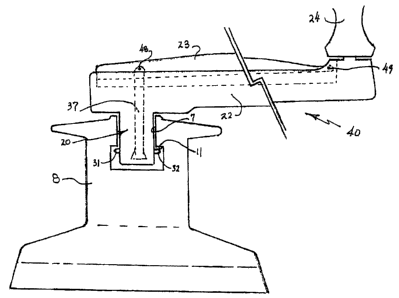
As best shown in Fig. 6, in order to conveniently actuate
the lock/release mechanism of the drive head 20, crank 40
is provided with a grip lever 23, to cause movement of
actuating shaft 37 up and down in bore 30. Lever 23 is
mounted for pivot motion on crank arm 22 by a pinned
joint to provide a fulcrum 49 at the distal end of crank
arm 22. A handle 24 is mounted at the distal end of
crank arm 22 in a well known manner.
Actuating shaft 37 may be pinned to the drive end of grip
lever 23 by a pin 48, as shown in Fig. 7, to allow a
slight pivot motion between shaft 37 and lever 23. In
17
CA 02503101 2005-03-30
another embodiment, actuating shaft 37 is constructed
with a head 55 that engages a key hole shaped slot 56
constructed in grip lever 23, as shown in Figs. 6a and
6b.
Lever 23 is biased upward by a coil spring 25 captured in
aligned bores 43 on lever 23 and 42 on crank arm 22, as
shown in Fig. 6. Other biasing arrangements may be used
without deviating from the scope of this invention. It
is observed that by biasing grip lever 23 so that it
pivots away from crank arm 22, the lock/release mechanism
21 is maintained in the locked position.
By griping lever 23 and closing the distance 1 between
lever 23 and crank arm 22, actuating shaft 37 will move
downward in bore 30 and release the pins 31 and 32 into a
retracted position. The drive head 20 of crank 40 may,
accordingly, be engaged in drive socket 7. With the
release of the grip lever 23, it travels upward, pulling
actuation shaft 37 with it and forcing pins 31 and 32
into engagement with shoulder 11.
As shown in Fig. 8, the insertion end 51 of a typical
drive head 50 for a crank is cut in a transverse plane to
the axis z of the drive head 51. This presents a flat
surface 52 having an octagonal profile.
18
CA 02503101 2005-03-30
To facilitate alignment of the drive head and socket, the
profile of the drive head 50', at its insertion end, is
altered, as shown in Fig. 9. The bi-square (or
octagonal) shape of the drive head 50' at its insertion
end 51' is defined by 8 triangular shaped projections 53'
extending the length of the drive head, parallel with the
longitudinal axis z' of the drive head 50'. In this
embodiment, of the invention, the sides of each of the
triangular projections 53' are bevelled at an angle
upward from the plane of the surface 52' of insertion end
51'. Each of the bevelled sides of a projection will
intersect in a line which is also bevelled upward in a
plane through the point of the projections 53'. This
results in the engaging surface of the drive head
presenting a compound bevelled surface 54' on each of the
triangular projections, thereby facilitating insertion of
the drive head in the socket.
In this manner a crank for a winch is constructed that
can be conveniently and reliably engaged utilizing one
hand. In addition the locking mechanism is more protected
from weather and damage.
It should be understood that the above description is
only illustrative of the invention. Various alternatives
and modifications can be devised by those skilled in the
art with out departing from the invention. Accordingly,
19
CA 02503101 2005-03-30
the scope of the present invention is intended to embrace
all such alternatives, modifications and variances.