Note: Descriptions are shown in the official language in which they were submitted.
CA 02503478 2005-04-01
FOLDING FRAME FOR A TRICYCLE, SCOOTER OR CHILD'S BICYCLE
Background of the Invention
[0001] The
invention relates to a folding frame for a
tricycle, scooter or child's bicycle. The
frame having a
front frame part on which the front wheels can be mounted at
least indirectly, and a rear frame part on which the rear
wheels can be mounted. A swivelling joint with a front
articulated part and a rear articulated part connects the
front and the rear frame part. The front articulated part is
mounted on the front frame part and the rear articulated part
is mounted on the rear frame part.
[0002]
Such a frame is known from a tricycle which is
offered by the company Radio Flyer under the name 421 Ready
To Ride Trike". The tricycle can be folded up out of the
position of use in order to be brought into a compact, space-
saving position. The joint, and the locking mechanism for the
joint, are extremely complex. The known tricycle has
specifically a joint of different sheet metal parts which can
be swivelled against one another and which can be swivelled
around various swivelling axes against one another. The two
frame parts are locked against one another in the position of
use via a hook.
[0003] The
production of the joint is complex in mounting
and in storage.
[0004] It
is an object of this invention is to provide a
frame for a tricycle, scooter or child's bicycle which has a
joint between a first frame part and a second frame part. The
joint is structurally simple and has a simple locking
mechanism.
Summary of the Invention
[0005] An
object is achieved by a frame which includes a
first of the two articulated parts, specifically the front and
the rear articulated part, which has a first recess and the
second of the two articulated parts has a second recess and a
third recess. The first recess and the second recess in the
1
CA 02503478 2005-04-01
position of use of the frame are in alignment with one
another, while the first recess and the third recess in the
folded position are in alignment with one another. The first
articulated part and the second articulated part can then be
locked against one another in the position of use and in the
folded position via a pin which can be moved in the recesses.
The swivelling joint of the frame has only one swivelling
axis. The frame with the swivelling joint is structurally
simpler than the known frame and in particular does not have
any pinching or shearing points which could be objectionable
in terms of safety. The frame is therefore also especially
suited for vehicles which are used by children.
[0006] Advantageously the pin in the frame can be moved
parallel to the swivelling axis of the joint. But basically,
it is also conceivable for the pin to be able to move at a
right angle to the swivelling axis. In the position of use,
and the folded position, the pin can be held by a spring in
the two recesses which are in alignment. Thus the joint cannot
unlock itself. On the other hand, the spring advantageously
enables automatic locking of the joint in the position of use
and/or in the folded position.
[0007] The second and the third recess can be joined to one
another via a guide slot. The recesses are then advantageously
provided as enlargements of the guide slot. These enlargements
can then be located especially on the ends of the guide slot.
[0008] The pin can have a first segment, which in the
position of use, and/or in the folded position, fits into the
two recesses which are in alignment at the time. The pin can
have a second segment which is offset relative to the first
segment and which in the positions of the frame between the
position of use and in the folded posi*tion fits into the guide
slot.
[0009] In the frame, one of the two articulated parts can
have a receiver in which the other articulated part is located
with a swivelling capacity.
[0010] Furthermore the swivelling joint of a frame can have
a holding part in which the pin is movably supported. In the
2
CA 02503478 2012-04-27
holding part, there can be a recess which is in alignment with
the first recess and in which the pin and the spring are
located.
[0010a] More particularly, there is disclosed a folding
frame for a tricycle, scooter or child's bicycle, comprising:
a front frame part on which front wheels can be mounted at
least indirectly, a rear frame part on which rear wheels can
be mounted, a swivelling joint with a first front articulated
part which is mounted on the front frame part, and with a
second rear articulated part which is mounted on the rear
frame part, the first of the two articulated parts has a first
recess and the second of the two articulated parts has a
second recess and a third recess, the first recess and the
second recess in a position of use of the frame are in
alignment, and the first recess and the third recess in a
folded position are in alignment, the first articulated part
and the second articulated part are locked against one another
in the position of use and in the folded position via a pin
which can be moved in the recesses, the first articulated part
has a receiver in which the second articulated part is located
with a swivelling capacity, the swivelling joint has a holding
part in which the pin is movably supported, and the holding
part is located between two disks of the second articulated
part, the holding part being torsionally strong relative to
the first articulated part.
[0010b] In another aspect, there is disclosed a folding
frame for a tricycle, scooter or child's bicycle, comprising:
a front frame part on which front wheels can be mounted, a
rear frame part on which rear wheels can be mounted, a
swivelling joint with a first front articulated part which is
mounted on the front frame part, and with a second rear
3
CA 02503478 2012-04-27
articulated part which is mounted on the rear frame part, the
first articulated part terminating in a forked end, the first
forked end having a first recess the second articulated part
terminating in a forked end, the second forked end having a
second recess and a third recess and fitting within the first
forked end, a holding part retained within the second forked
end, a pin within the holding part engaging the first recess
and one of the recesses in the second forked end.
Brief Description of, the Drawings
[0011] A
tricycle with a frame is detailed using the
following drawings.
[00].2]
Figure 1 shows the tricycle with the frame in the
position of use;
[0013]
Figure 2 shows the tricycle with the frame in the
folded position;
[0014]
Figure 3 shows a section through the swivelling
joint; and
[0015]
Figure 4 shows an exploded view of the swivelling
joint with bordering parts of the frame.
Detailed Description of the Invention
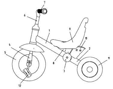
[0016] The
tricycle shown in Figures 1 and 2 has a frame
consisting of a front frame part 1 and a rear frame part 2
which are joined to one another via a swivelling joint 3. In
the front frame part, a fork 4 is pivotally mounted. The
front wheels 5 are mounted on the fork 4. On the top end of
the fork 4, there are the handlebar stanchion 6 and the
handlebars 7. On the front frame part, a repeatedly bent sheet
of metal 8 is mounted, to which the seat 9 is attached. The
repeatedly bent sheet 8 has a receiver for a holding device 10
in which a connecting rod (not shown) can be inserted.
3a
CA 02503478 2012-04-27
[0017] Proceeding from the swivelling joint 3, the rear
frame part 2 branches so that it has two back ends. On these
back ends, the wheels 11, which form the rear wheels of the
tricycle, are mounted. The tricycle can be driven via pedals
12 on the front wheel.
[0018] The swivelling joint of the tricycle is described
below using Figures 3 and 4. The swivelling joint 3 has a
front articulated part 31 and a rear articulated part 32. The
front articulated part 31 is mounted on the back end of the
3b
CA 02503478 2005-04-01
_
front frame part 1. The rear articulated part 32, conversely,
is mounted on the front end of the rear frame part 2.
[0019] The front articulated part 31 has two circular disks
33 which are spaced part, parallel to one another, and which
each have a central hole and holes 34 which are in alignment
with one another. One of the circular disks 31 has a first
eccentric hole 35 which forms a first recess.
[0020] The second articulated part 32 has two circular
disks 36 which are spaced apart from one another and parallel
to one another. These circular disks 36 have central holes 37
which are in alignment with one another. In one circular disk
36, of the second articulated part 32, there is a guide slot
38 with a second hole 39 on its one end and a third hole 40 on
its other end, which form a second recess and a third recess.
The second hole 39 is arranged such that it is in alignment
with the first hole 35, on the first articulated part 31, in
the position of use of the frame. The second hole 40,
conversely, is in alignment with the first hole 35 of the
first articulated part 31 in the folded position of the frame.
[0021] The distance of the surfaces of the two circular
disks 36, of the second articulated part 32, which surfaces
point to the outside, is dimensioned such that it is smaller
than, or equal to, the distance of the surfaces of the
circular disks 33, of the first articulated part, which
surfaces point to the inside. The two circular disks 33, of
the first articulated part, form a receiver into which the
second articulated part 32 is inserted. The central holes 34
of the circular disks 33, of the first articulated part 31,
are in alignment with the central holes 37 of the circular
disks 36 of the second articulated part 32.
[0022] The swivelling joint 3 has a plastic injection
molded part which is labelled as holding means 41 and which
has essentially the shape of a hollow cylinder which is closed
on one side. This hollow cylinder, on its closed side, has a
central hole to which a sleeve 42 is attached inside.
Furthermore, a sleeve 43, on the inside, is inserted into the
interior of the hollow cylinder. The holding means 41 is
4
CA 02503478 2005-04-01
inserted between the two disks 36 of the second articulated
part 32, the central hole 37 being in alignment with the
sleeve 42.
[0023] The holding means 41 is located between the disks 36
of the second articulated part 32, but is torsionally strong
relative to the first articulated part 31. With respect to the
first articulated part 31, the holding means 41 is arranged
such that the sleeve 43 is in alignment with the first hole
35, regardless of the position of the frame. By means of a
screw 44, which is inserted through the central holes 34, 37,
of the circular disks 33 and 36, and through the central
sleeve 42 of the holding means 41, and which is secured by a
nut 45, the swivelling joint is held together.
(0024] In the sleeve 43, of the holding means 41, on the
one hand a spring 46, and on the other hand, a pin 47, is
inserted. The pin has a first segment, which is facing the
spring, and a second segment which is offset from the first
segment. The first segment has a diameter which corresponds to
the inside diameter of the second hole 39, and the third hole
40, so that the pin can be inserted into these holes 39, 40.
The second segment, conversely, has a diameter which is
dimensioned such that the second segment can fit into the slot
38 of the circular disk 36 and can extend through the first
hole 35.
[0025] In the position of use of the frame and in the
swivelled-in position of the frame, the pin 41 with its first
segment and the second segment is pushed through the second
hole 39 and the third hole 40. The second segment then
projects through the first hole 35. The offset between the
first and the second segment adjoins the edge of the first
hole 35. To swivel the frame, the pin 47 can be pressed from
the outside against the pressure of the spring 46 to the
inside. In this way, the pin, with its first segment, is
lifted out of the second hole 39 and the third hole 40. The
swivelling joint 43 is then unlocked. The first frame part 1
can then be swivelled against the second frame part 2. During
swivelling, or in the position between the position of use and
CA 02503478 2005-04-01
the folded position, the first segment of the pin 47 lies on
_
the edge of the guide slot 38, while the second segment
extends through the guide slot 38 and the first hole 35.
6