Note: Descriptions are shown in the official language in which they were submitted.
-1-
SYSTEM FOR DETECTING STRUCTURAL DEFECTS AND
FEATURES UTILIZING BLACKBODY SELF-ILLU1VDNATION
GOVERNMENT CONTRACT
[0001] The United States Government has certain rights to this invention
pursuant to
Contract No. DACA 72-99-C-011 awarded by SERDP.
FIELD OF THE INVENTION
[0002] The present invention relates to detection of structural features, and
more
particularly relates to a system which utilizes blackbody self-illumination to
observe defects and
other structural features of coated objects such as aircraft components.
BACKGROUND INFORMATION
[0003] Aircraft components are subject to constant degradation such as
corrosion and
cracking caused by environmental and operational conditions. Although the
application of
coatings, such as paints, reduces corrosion problems substantially, they
typically cannot eliminate
them entirely. 'Furthermore, stress experienced during flight can result in
damage which a
coating of paint cannot mitigate, such as stress defects and cracking. In
order to ensure that
aircraft are ready for flight, periodic inspections are necessary.
[0004] Inspection of aircraft components traditionally includes visual
inspection. When
visually inspecting aircraft components, the coating used to protect the
components becomes an
obstacle because it may hide structural defects or features beneath the
coating. It is therefore
necessary to strip the component assembly or aircraft in question of its paint
before a proper
visual inspection can be performed. Afterward, a new coating of paint must be
applied. This
process results in substantial expense in the form of labor and materials,
raises environmental
concerns, and requires a great amount of time.
[0005] Apart from the inefficiency of visual inspection methods, another
problem is that
visual inspection is not always effective. While a skillful eye may pick up
most human-visible
defects with a satisfactory degree of consistency, some defects may be very
small or lie under the
~oss~i~
~CA 02503560 2005-04-06
-2-
surface of the component. In many cases these defects will go unnoticed by
visual inspection
regardless of the skill and experience of the observer.
[0006] In addition to visual inspection, active thermography techniques have
been
proposed for inspection of various components. One such technique utilizes a
transient heat
source to heat the component, followed by detection of a transient heat
signature on the surface
of the component to determine the presence of anomalies or defects. However,
such techniques
require specialized equipment and controls to generate the necessary transient
heating, and are
inefficient because detection of the transient thermal signature can require a
significant amount
of time.
[0007] U.S. Published Patent Application No. US 2004/0026622 A1 discloses a
system
for imaging coated substrates which utilizes an infrared (IR) light source.
The IR light shines on
the object and is reflected to a focal plane array. While such a system may be
useful for some
applications, an IR light source is required and the incident IR radiation
must make two passes
through the coating. Furthermore, a portion of the incident radiation may
reflect off the surface
of the coating, thereby obscuring the image of the underlying substrate.
[0008] The present invention has been developed in view of the foregoing.
SUMMARY OF THE INVENTION
[0009] The present invention utilizes the substantially steady-state
temperature of a
coated object, in conjunction with an optical detection system, to selectively
view defects and
features of the object below the coating without the necessity of transient
heating or IR
illumination and reflectance imaging. The optical detector, such as an IR
camera, may be
tailored for the wavelengths at which the coating material is substantially
transparent, thereby
maximizing the viewing clarity of the defects and features under the coating,
and distinguishing
them from any spurious features on the top surface of the coating. The present
system enables
the inspection of small or large areas in real time, without requiring complex
image acquisition,
storage and image processing equipment and software.
[0010] An aspect of the present invention is to provide a method of inspecting
a coated
object. The method includes maintaining substantially steady state blackbody
radiation from the
~o3s~ i
CA 02503560 2005-04-06
-3-
object, and detecting structural features of the object under the coating
based on the blackbody
radiation.
[0011] Another aspect of the present invention is to provide a system for
inspecting a
coated object. The system comprises means for maintaining substantially steady
state blackbody
radiation from the object, and means for detecting structural features of the
object under the
coating based on the blackbody radiation.
[0012] A further aspect of the present invention is to provide a system for
inspecting a
coated object comprising a camera structured and arranged to detect structural
features of the
object under the coating based on substantially steady state blackbody
radiation generated from
the object.
[0013] These and other aspects of the present invention will be more apparent
from the
following description.
BRIEF DESCRIPTION OF THE DRAWINGS
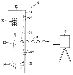
[0014] Fig. 1 is a schematic illustration of a system for detecting structural
features of a
coated object utilizing blackbody self-illumination of the object.
[0015] Fig. 2 is a schematic flow diagram illustrating the detection of
blackbody radiation
from an object to be inspected in accordance with an embodiment of the present
invention.
[0016] Figs. 3-26 are blackbody infrared radiation images of coated graphite
panels and
coated aluminum panels in accordance with various embodiments of the present
invention.
[0017] Figs. 27a-d are visible, IR reflectance, and IR blackbody radiation
images of a
coated aircraft panel with rivets, showing features of the rivets underneath
the coating in
accordance with a blackbody self illumination embodiment of the present
invention.
DETAILED DESCRIPTION
[0018] Fig. 1 schematically illustrates a detection system in accordance with
an
embodiment of the present invention. A coated object 1U, such as an aircraft
component,
composite panel, painted panel, ship hull, ground vehicle, aircraft assembly,
aircraft landing gear,
metallic substrate, honeycomb bonded assembly or the like, includes a
substrate or object 12 at
~o3s~ i
CA 02503560 2005-04-06
-4-
least partially covered with a coating 14 such as paint, composite matrix
material or the like.
Examples of some specific coatings include coatings manufactured to the
following
specifications: BMS 10-72; BMS 10-1 l; BMS-10-79, BMS 10-60; MiL-PRF-23377;
MiL-PRF-
85582; MiL-PRF-85285 and TT-P-2760. In accordance with the present invention,
the object 12
emits blackbody radiation B toward a detector 16 such as an infrared (IR)
camera, IR detector or
the like.
[0019] In accordance with the present invention, the blackbody radiation B
from the
object 12 is generated in a substantially steady state. As used herein, the
term "substantially
steady state blackbody radiation" means the radiation naturally generated from
the object to be
inspected due to its maintenance at a temperature above zero degrees Kelvin,
typically at room
temperature or a slightly elevated temperature. Steady state blackbody
radiation results from
maintaining the object or a portion thereof at a substantially uniform
temperature, i.e., in the
absence of significant thermal gradients throughout the object or portion
thereof being inspected.
[0020] Since the object 12 is at or near room temperature, it emits a
significant amount of
substantially steady state infrared (IR) blackbody thermal radiation B. In
contrast, the coating 14
may be substantially transparent at some of the wavelengths at which the
underlying object emits
the blackbody radiation B. Many organic polymers that may be used in the
coating 14 are
significantly IR-transnussive in certain spectral bands. The blackbody
radiation B of the object
can penetrate the organic coating 14 covering the object 12 and reveal the
surface condition of
the object 12 under the coating 14. The radiation B transmitted through the
coating 14 is thus
used to provide images from the self-illuminated object 12 that reveal any
defects such as
corrosion, cracks and pits, as well as other structural features under the
coating 14. The object 12
to be inspected becomes observable by its own 1R radiation B, which is a
function of the
temperature of the object 12.
[0021] As shown in Fig. 1, the object 12 to be inspected may include various
types of
structural features. The structural features may be located on the surface of
the object 12 under
the coating 14, or may be located below the surface of the object 12. For
example, surface
features 22 may be provided on the surface of the object 12 below the coating
14. Examples of
surface features 22 include indicia such as alphanumeric symbols, marks,
codes, part numbers,
bar codes and the like. The object 12 may also include surface defects such as
corrosion 24, pits
703571v
CA 02503560 2005-04-06
-5-
26, cracks 28, gouges, and other structural defects. As shown in Fig. 1, the
object 12 may also
include structural features below the surface of the object 12, such as
corrosion 32, cracks 34,
composite reinforcements 36 and pits 26.
[0022] Fig. 2 schematically illustrates a blackbody radiation detection
process in
accordance with an embodiment of the present invention. Blackbody radiation
from an object
such as the coated object 10 shown in Fig. 1 is transmitted to a detector such
as an IR camera.
After detection, an image of the coated object 12, including structural
features of the object 10
under the coating 14 may be displayed and/or stored. In addition, the image
may be transmitted
by any suitable means such as the Internet, wireless, cable or satellite for
display and/or storage at
any desired location.
[0023] In accordance with an embodiment of the present invention, the steady
state
blackbody radiation B from the object to be inspected may be generated by
holding the object at
room temperature. The entire object may be maintained at a substantially
uniform temperature at
or near room temperature. As used herein, the term "room temperature" means
the surrounding
ambient temperature found in an area such as a testing laboratory, production
facility, warehouse,
hanger, airstrip, aircraft cabin or ambient exterior temperature. Room
temperatures are typically
within a range of from about 60 to about 80° F. However, temperatures
above or below such a
range may exist. For example, in cold environments such as unheated hangers or
warehouses in
cold regions, the room temperature may be 32° F or lower. In warm
environments such as non-
air-conditioned hangers and warehouses in desert or tropical regions, the
"room temperature"
may be well above 80° F, e.g., up to 100 or 110° F, or even
higher.
[0024] In accordance with another embodiment of the present invention, the
object to be
inspected is held at an elevated temperature, e.g., above room temperature, to
maintain the
substantially steady state blackbody radiation. Such an elevated temperature
may be up to about
120° F or higher, typically in a range of from 80 to about 110°
F. The elevated temperature may
be maintained by any suitable means, such as exposure to sunlight, heat gun,
heat lamp, thermal
blanket, hot packs, human contact and the like.
[0025] The detector 16 may selectively detect radiation at certain wavelengths
at which
the coating 14 is substantially transparent: In this manner, the coating 14
does not substantially
interfere with the image from the object 12. The detector 16 may include any
suitable device
703571v
CA 02503560 2005-04-06
-6-
such as an IR camera, IR detector, IR focal plane or the like. For example,
the camera may be an
analog or digital camera, and may record still or video images. Infrared
cameras may be used,
for example, cameras which detect mid-infrared radiation, e.g., having
wavelengths between
about 3 and about 5 microns. Such mid-llt wavelengths have been found to
produce relatively
sharp images with minimal interference from several types of coatings. Other
infrared cameras
include near-infrared cameras which detect wavelengths between about 0.7 and
about 3 microns,
and far-infrared cameras which detect wavelengths between about 3 and about 12
microns.
[0026] In addition to the camera 16, standard filters and/or polarizers (not
shown) may be
positioned in the optical path of the blackbody radiation B between the object
12 and the detector
16. Such filters and/or polarizers may remove a portion of the blackbody
radiation B having
wavelengths at which the coating 14 is non-transparent.
[0027] The detector 16 may include a portable or movable camera such as a hand-
held
camera or a camera that may be mounted on a tripod or the like that can be
moved by means of a
pan feature and/or a tilt feature.
[0028] In accordance with an embodiment of the present invention, the detected
image of
the object 12, including the detected structural features, may be compared
with a reference
image. For example, a reference image may be generated from another object
similar to the
coated object that is known to be substantially free of defects. By comparing
a substantially
defect-free reference object to the coated object being inspected, manual or
automated
evaluations may be performed. The reference image used as the standard could
be
preprogrammed into a database and a comparison made between the reference
image and the
image created from paint under test. Acceptability criteria could be
preprogrammed as well,
unacceptable areas could be highlighted in red and acceptable areas in green.
Other colors could
be selected, as well, such as gray for an area requiring more evaluation.
[0029] The following examples are intended to illustrate the various aspects
of the
present invention and are not intended to limit the scope of the invention.
703571v
CA 02503560 2005-04-06
EXAMPLE 1
[0030] As shown in Fig. 3, a painted graphite panel comprising epoxy graphite
with an
epoxy primer and urethane top coat paint was imaged with a mid-IR camera at
the wavelength of
3 to 5 microns. During the imaging process, the panel was held at 89°F.
The panel was
subjected to a room temperature calibration which involved adjusting pixel
intensity to make
focal plane uniform and linear within selected room temperature (RT)
calibration.
EXAMPLE 2
[0031] As shown in Fig. 4, a painted graphite panel comprising epoxy graphite
and epoxy
primer and urethane top coat paint was imaged with a mid-IR camera at a
wavelength of 3 to 5
microns with the panel held at a temperature of 90°F. The panel was
subjected to hot calibration
at a temperature of 84°F. The hot calibration process involved
adjusting pixel intensity to make
focal plane uniform and linear within selected 84°F calibration.
EXAMPLE 3
[0032] As shown in Fig. 5, a composite panel comprising epoxy graphite and
laminated
copper fiber painted with epoxy primer and urethane top coat was imaged with a
mid-IR camera
at a wavelength of 3 to 5 microns, with the panel maintained at a temperature
of 90°F. The panel
was subjected to hot calibration at 84°F, as described above.
EXAMPLE 4
[0033] As shown in Fig. 6, a painted graphite and copper fiber panel similar
to the panel
of Example 3 was imaged at a temperature of 74°F. The panel was
subjected to hot calibration at
84°F.
EXAMPLE 5
[0034] As shown in Fig. 7, a panel comprising epoxy graphite with a laminated
copper
weave painted with epoxy primer and urethane top coat was imaged at a
temperature of 91°F.
The panel was subjected to room temperature calibration.
possum
CA 02503560 2005-04-06
_g_
EXAMPLE 6
[0035] As shown in Fig. 8, a painted graphite and copper weave panel similar
to that of
Example 5 was imaged at 87°F after room temperature calibration.
EXAMPLE 7
[0036] As shown in Fig. 9, a painted graphite and copper weave panel similar
to that of
Examples 5 and 6 was imaged at 82°F after room temperature
calibration.
EXAMPLE 8
[0037] As shown in Fig. 10, an epoxy graphite panel painted with epoxy primer
and
urethane top coat was imaged at 90°F after room temperature
calibration.
EXAMPLE 9
[003$] As shown in Fig. 11, a painted graphite panel similar to that of
Example 8 was
imaged at 86°F after room temperature calibration.
EXAMPLE 10
[0039] As shown in Fig. 12, a painted graphite panel similar to that of
Examples 8 and 9
was imaged at 82°F after room temperature calibration.
EXAMPLE 11
[0040] As shown in Fig. 13, a painted graphite panel similar to that of
Examples 8-10
was imaged at 78°F after room temperature calibration.
EXAMPLE 12
[0041] As shown in Fig. 14, a panel comprising epoxy graphite was primed with
epoxy
primer and painted with epoxy primer and urethane top coat on the right side
of the panel. Fig.
14 is a visible image of the painted and primed panel.
703571v
CA 02503560 2005-04-06
-9-
EXAMPLE 13
[0042] As shown in Fig. 15, a panel comprising graphite with copper weave was
primed
with epoxy primer in lower right hand side and painted with urethane top coat
in upper right of
panel. In Fig. 15, the left side of the panel is unprimed and unpainted, while
the right side is
primed and painted. Fig. 15 is a visual image of the panel.
EXAMPLE 14
[0043] Fig. 16 is a visible image of an aluminum panel comprising a corroded
aluminum
substrate coated with epoxy primer and urethane top coat.
EXAMPLE 15
[0044] Fig. 17 is an IR reflectance image of the panel of Example 14 at
77°F. The IR
reflectanct image was generated by reflecting IR radiation off the aluminum
substrate detecting
the reflected energy in an IR camera or detector. The corrosion is indicated
in dark areas.
EXAMPLE 16
[0045] Fig. 18 is an IR reflectance image of the panel of Example 14 taken
75°F. The
corrosion is indicated in dark areas.
EXAMPLE 17
[0046] Fig. 19 is a blackbody radiation image made in accordance with the
present
invention of the coated aluminum panel of Example 14. The panel was maintained
at a
temperature of 84°F with a room temperature calibration. The corrosion
is indicated in light
areas.
703571v
CA 02503560 2005-04-06
- 10-
EXAMPLE 18
[0047] Fig. 20 is a blackbody radiation image made in accordance with the
present
invention of the coated aluminum panel of Example 14, at 78°F with a
room temperature
calibration. The corrosion is indicated in light areas.
EXAMPLE 19
[0048] Fig. 21 is a blackbody radiation image made in accordance with the
present
invention of the coated aluminum panel of Example 14, at 72°F with a
room temperature
calibration. The corrosion is indicated in light areas.
EXAMPLE 20
[0049] Fig. 22 is an IR reflectance image of a corroded aluminum panel coated
with an
epoxy low IR primer and urethane top coat. The IR reflectance image was made
by reflecting IR
radiation off the coated aluminum substrate and detecting the reflected energy
in an IR camera.
The corrosion is indicated in dark areas.
EXAMPLE 21
[0050] Fig. 23 is a blackbody radiation image produced in accordance with the
present
invention taken from the same primed and top coated aluminum panel described
in Example 20.
The blackbody radiation procedure was performed at 96°F with a
78°F hot calibration. The
corrosion is indicated in light areas.
EXAMPLE 22
[0051] Fig. 24 is a blackbody radiation image produced in accordance with the
present
invention taken from the same primed and top coated aluminum panel described
in Example 20.
The blackbody radiation procedure was performed at 86°F with a
78°F hot calibration. The
corrosion is indicated in light areas.
~oss~ i
CA 02503560 2005-04-06
-11
EXAMPLE 23
[0052] Fig. 25 is a blackbody radiation image produced in accordance with the
present
invention taken from the same primed and top coated aluminum panel described
in Example 20.
The blackbody radiation procedure was performed at 79°F with a
78°F hot calibration. The
corrosion is indicated in light areas.
EXAMPLE 24
[0053] Fig. 26 is a visible image of the primed and top coated aluminum panel
of
Examples 20 to 23.
[0054] The foregoing examples demonstrate that blackbody type IR radiation is
capable
of passing through coatings and producing an image. External illumination is
not required, i.e.,
the parts are self-illuminating.
EXAMPLE 25
[0055] A bolted aluminum aircraft panel was coated with Epoxy primer MMZL,-PRF-
23377TYI and Urethane MIL-PRF-85285TYI paint, as shown in Fig. 27a. It was
inspected using
visible imaging (Fig. 27b), IR reflectance imaging (Fig. 27c), and IR
blackbody imaging (Fig.
27d). The blackbody self-illumination image was made with a mid-IR camera at a
wavelength of
3 to 5 microns. During the black body imaging process, the painted aluminum
panel was held at
a temperature of 85 to 95°F. As shown in Fig. 27d, details of the bolt
heads, including
alphanumeric symbols, can be seen in the IR blackbody image which are not
detectable from the
visible image of Fig. 27b.
[0056] An advantage of the present blackbody self illumination system is that
an
independent IR illumination source is not needed. In some cases, an object's
IR radiation at
ambient temperature may be sufficient to allow imaging of the object through
the coating, while
in other situations moderate heating of the object to a slightly elevated
temperature may be
desirable. Such heating can be achieved naturally, e.g., by sunlight, or by a
heat gun, thermal
~o3s~ i
CA 02503560 2005-04-06
- 12-
blankets, an IR heat lamp, or by other means that produce a substantially
steady-state temperature
of the object.
(0(157] Another advantage of the present blackbody system is that the IR
radiation only
has to make one pass through the coating. This is more efficient compared to
IR reflectance
techniques, in which IR radiation from an external illuminator must first
penetrate the coating,
reflect off the substrate or object and pass through the coating again. An
additional advantage of
the present blackbody method is the reduction or elimination of the coating
surface reflection. In
the reflectance method, IR energy is reflected off the coating surface
partially obscuring the
image from the substrate underneath.
[0058] Whereas particular embodiments of this invention have been described
above for
purposes of illustration, it will be evident to those skilled in the art that
numerous variations of
the details of the present invention may be made without departing from the
invention as defined
in the appended claims.
703571v
CA 02503560 2005-04-06