Note: Descriptions are shown in the official language in which they were submitted.
CA 02503572 2005-04-25
1
P8051PCT
English Translation of PCT/EP03/11450
Retractable tail-lift with carriage guidance
The present invention concerns a retractable tail-lift for a vehicle in
accordance
with the pre-characterizing part of claim 1.
A retractable tail-lift of this type is disclosed e.g. by the Hydfalt 3 model
range of
the company Gerd Bar GmbH, Heilbronn.
Tail-lifts are mounted to lorries or trailers for loading and unloading them.
Retractable tail-lifts are mounted to the chassis using a guiding mechanism
and
can be retracted completely under the body or chassis frame after folding the
platform once or twice, such that they do not project at any location to the
rear
beyond the body to prevent any disturbance. Retractable tail-lifts of this
type are
used for vehicles with interchangeable bodies and for all vehicles which must
dock onto loading/unloading regions of cold storage houses.
In the Hydfalt 3 model range, the guiding mechanism is formed by two guiding
rails in which the lifting mechanism with one vertical carriage each is
suspended,
and can be slidably moved between the working position located behind the
vehicle and the driving position located below the vehicle. Each carriage
comprises a front guiding element with an upper sliding member which abuts on
an upper guiding surface of the guiding rail, and a rear guiding element with
a
lower sliding member which abuts on a lower guiding surface of the guiding
rail.
The guidance is disposed inside the guiding rails to protect the guiding
surfaces
from dirt. The guiding rail may also be mounted at any location to the vehicle
or
to cross members, which facilitates dimensioning of the guiding rail. This
technology also provides maintenance-free sliding guidance if the sliding
partners
are appropriately selected. These sliding guidances have the object to adopt
the
net weight of the lifting mechanism and the platform and slidingly transfer it
to
the guiding element during folding and unfolding. The guiding elements also
have the object to assume horizontal guidance during forward and backward
CA 02503572 2005-04-25
2
movement. The centrally acting displacement cylinder and the irregular
friction
must simultaneously provide horizontal guidance. The unfavorable leverages
the separation of the guiding elements and the center of gravity of the tail-
lift -
also produce large horizontal guiding forces. Since the sliding materials,
which
consist substantially of plastic material or plastic composite material, are
subjected to wear, the sliding members of the Hydfalt 3 model range are
suspended on the carriage to obtain even wear. Towards this end, the symmetric
guiding construction has guiding elements of aluminium for the tension side as
well as the pressure side on both sides of the carriage plate. This guiding
elements comprise chambers which are open towards the bottom for receiving
the sliding elements, and are commonly borne by a specially disposed bolt
which
penetrates through the carriage plate. This construction requires relatively
high
precision and expensive measures to protect the support and bolt from rust.
Guiding surface is wasted on the pressure side of the carriage in the region
of
the carriage plate thickness. With this construction, the forces are deviated
through the bolt into the carriage plate, thereby producing a very large
internal
bore surface which necessitates great material solidity. The carriage plate
thickness must nevertheless be excessively thick. This conventional
construction
is therefore technically very demanding and therefore expensive.
It is therefore the object of the present invention to facilitate mounting of
the
guiding elements on the carriage of a retractable tai!-lift.
This object is achieved in accordance with the invention with an tail-lift in
accordance with claim 1. Further advantageous embodiments of the invention
are subject matter of the dependent claims.
Servicing of the inventive construction is extremely easy. Changing of the
sliding
members is very simple and requires no connecting means. Removal of the
guiding elements, replacing the sliding members, and reinsertion are
facilitated.
Faults caused by untrained staff are almost impossible. The same applies for
initial assembly.
Further advantages of the invention can be extracted from the description and
the drawing. The features mentioned above and below may be used individually
CA 02503572 2005-04-25
3
or in arbitrary combination. The embodiment shown and described is not to be
understood as exhaustive enumeration but has exemplary character for
describing the invention.
Fig. 1 shows a side view of the retractable tail-lift in its retracted
travelling
position and in its extended working position;
Fig. 2 shows a carriage which can be displaced in a guiding rail, of the
underridable elevating platform of Fig, i;
Fig. 3 shows a detailed view of the carriage of Fig. 2 in the region of a
front
guiding element;
Fig. 4 shows a detailed view of the carriage of Fig. 2 in the region of a rear
guiding element; and
Fig. 5 shows a sectional view in accordance with II-II of Fig. 2.
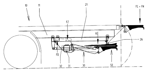
Fig. 1 shows the tail-lift in its retracted travelling position, with folded
platform
50, installed on the rear of a trailer 10. The lifting mechanism 30 with
platform
50 is connected to the trailer 10 via guiding elements 40a, 40b (Fig. 2) in
the
region FZ and FD using two guiding rails 21. The center of gravity of the net
weight of lifting mechanism 30 and platform 50 is in the region of FE. This
force
generates the tractive force in FZ and the compressive force in FD.
In the working position of the tail-lift, shown in broken view, the net weight
FE
and the useful load FN act on the platform 50, which generate the largest
forces
in FZ and FD in this case. During stowage, the lifting mechanism 30 with
folded
platform 50 is moved into the travelling position. The support arms and
platform
50 remain below the level of the rubber buffers 26. The platform 50 is
subsequently lifted against the rubber buffers 26 using the lifting function
to
clamp the tail-lift. This increases of course the forces acting in FZ and FD.
Fig. 2 shows part of the support tube 31 with vertical carriage plate 32 in
the
guiding rail 21 shown with dashed lines. The region FZ shows the position of
the
CA 02503572 2005-04-25
4
guiding element 40b. In the region FD, the front guiding element 40a is
supported on the recess 32.5 (Fig. 3) which is open to the top of the carriage
32.
In the region FZ, the rear guiding element 40b penetrates through the carriage
32 in the region of the opening 32.3 (Fig. 4). In the region FD, the
arrangement
and the force transmission are analog to FZ, however, with the difference,
that
the recess 32.5 opens to the top.
Fig. 3 shows the front guiding element 40a which consists of the sliding
member
carrier 41a and the sliding member 42a which positively engage each other. The
front sliding member carrier 41a is loosely attached from above onto the plate-
shaped carriage 32, is guided thereon in a vertically displaceable manner and
is
disposed to be tilted due to sufficient play. Towards this end, the sliding
member
carrier 41a has guiding recesses 41.1 on its front end, which extend over the
vertical surface 32.4 of the carriage 32. The force is transmitted to the
sliding
member carrier 41a in the region FD via the radius-shaped abutment surface
32.6 of the recess 32.5 which is convexly curved (radius R) into the recess
32.5.
The forces are transmitted in a planar manner from the sliding member carrier
41a to the sliding member 42a and from the sliding member 42a to the upper
sliding path 21.2 (Fig. 5) of the guiding rail 21. The sliding member carrier
41a,
viewed transversely to the guiding direction of the carriage 32, and the
sliding
member 42a, viewed in the guiding direction of the carriage 32, each have a U-
shaped cross-section and positively engage each other over their full
surfaces.
Fig. 4 shows the rear guiding element 40b which consists of the sliding member
carrier 41b and the sliding member 42b. The rear sliding member carrier 41b
penetrates through the carriage 32 in the opening 32.3 which must be
sufficiently large to permit mounting of the sliding member carrier 41b
including
sliding member 42b. The rear sliding member carrier 41b is loosely attached
from below onto the plate-shaped carriage 32 and can be displaced thereon in a
vertical direction and can also be tilted due to sufi=ICient play. Towards
this end,
the sliding member carrier 41b has guiding recesses 41.1 on its front end
which
extend over the vertical surface 32.4 of the carriage 32. The force is
transmitted
to the sliding member carrier 41b in the region FZ through the radius-shaped
abutment surface 32.3 of the opening 32.2 which is convexly curved (radius R)
into the opening 32.3. The forces are transmitted in a planar manner from the
CA 02503572 2005-04-25
sliding member carrier 41b to the sliding member 42b and from the sliding
member 42b to the lower sliding path 21.1 (Fig. 5) of the guiding rail 21. The
sliding member carrier 41b, viewed transversely to the guiding direction of
the
carriage 32, and the sliding member 42b, viewed in the guiding direction of
the
carriage 32, each have a U-shaped cross-section and positively engage each
other over their full surfaces.
Fig. 5 shows a section through the longitudinal carrier 11 of the trailer 10,
the
carriage 32 and the guiding rail 21 in the region between FZ and FD. It is
clearly
shown that the guiding elements 40a, 40b guide the carriage 32 via the sliding
members 42a, 42b and the sliding member carrier 41a, 41b in a vertical
direction
on the lower sliding path 21.1 and also on the upper sliding path 21.2. The
horizontal guidance is obtained by the vertical surfaces of the sliding
members
42 on the vertical inner surfaces 21.3 of the guiding rail 21. The horizontal
guiding forces are transmitted from the sliding member 42 to the sliding
member
carrier 41 through positive engagement of these two parts. The positive
connection of the guiding elements 40 and the carriage 32 is obtained through
positive engagement of the guiding recesses 41.1 which extend over the
vertical
surface 32.4 (Figs. 3, 4) of the carriage 32. In the embodiment shown, the two
sliding member carriers 41a, 41b and their sliding members 42a, 42b have the
same design.
This carriage guidance requires a minimum number of components which cannot
be reduced. The laser-cut carriage 32 can be connected to the support tube 31
through welding. The guiding elements 40 can be easily inserted due to their
positive shape before assembly with the guiding rail 21. The guiding elements
40
connect the lifting mechanism 30 and the platform 50 to the guiding mechanism
20. The sliding member carriers 41 are simple milled parts of normal
constructional steel. The carriage 32 itself is produced from high-tensile
fine-
grained steel. The sliding member 42 is connected to the sliding member
carrier
41 also through pure positive locking in all directions of force without any
connecting means. The radius-shaped surfaces 32.2, 32.6 in the opening 32.3
and in the recess 32.5 ensure full-surface abutment of the sliding members 42
on the lower sliding path 21.1 and upper sliding path 21.2 through tilting of
the
sliding member carriers 41a, 41b. Even when the sliding members 42 are worn,
CA 02503572 2005-04-25
6
uniform surface pressure between sliding member 42 and the lower sliding path
21.1 and upper sliding path 21.2 is ensured.
If the material has been appropriately selected, e.g. high-tensile fine-
grained
steel on the carriage 32 and a relatively soft constructional steel on the
sliding
member carrier 41, the material will flow when the material strength has been
exceeded until the surface has enlarged to a sufFicient degree such that the
material can adopt the forces. This process occurs in magnitudes of far less
than
a millimeter and therefore has no effect on the function. The same applies for
inaccuracies produced by the support tube 31 and the carriage 32. Deviations
from the right angle in the horizontal plane caused by production can be
compensated for in the same manner.