Note: Descriptions are shown in the official language in which they were submitted.
CA 02503690 2005-04-04
OPTICAL CONNECTOR WHICH CAN BE DISASSEMBLED AND
DISASSEMBLING TOOL SUITABLE TO DISASSEMBLE THE SAME
This application claims priority to prior Japanese patent application JP
2004-110130, the disclosure of which is incorporated herein by reference.
~ackgJround of t~.Q, Invention:
This invention relates to an optical connector which can be
disassembled, a disassembling tool for disassembling the optical connector,
and a method of using the disassembling tool.
For example, Japanese Patent Publication (JP-B) No. 3354503
discloses an optical connector which can be disassembled and a tool for use in
disassembling the optical connector. The optical connector comprises a
housing and a ferrule removably attached to the housing. The housing has a
pair of locking members. On the other hand, the ferrule has a flange portion.
When the ferrule is attached to the housing, the flange portion is located
between the locking members to be locked therewith. The ferrule is connected
to an optical fiber.
The tool serves to attach and remove the ferrule to and from the
housing and is called a ferrule attaching tool. The ferrule attaching tool has
a
grip portion for an operator to grip, and a pair of elastic clamping members
connected to the grip portion and adapted to clamp the ferrule.
In order to remove the ferrule from the housing, the elastic clamping
members are inserted inside the locking members to force the locking members
outward. As a consequence, the locking members are disengaged from the
CA 02503690 2005-04-04
2
flange portion of the ferrule. Thereafter, the ferrule is clamped by the
elastic
clamping members and removed from the housing. In this manner, the optical
connector is disassembled. In order to attach the ferrule to the housing, an
operation is carried out in the manner reverse to that mentioned above.
With the above-mentioned structure, the ferrule is attached and
removed to and from the housing in the state where an optical fiber is
protected
by the ferrule. Therefore, the optical fiber is prevented from being bent and
damaged during attaching and removing operations.
Recently, proposal is made of an optical connector of the type such that
an optical fiber is inserted into an aligning member and directly connected to
a
mating optical connector. The optical connector of the type does not use the
ferrule so that the optical fiber may often be bent and damaged.
If the optical fiber is bent and damaged, the optical fiber must be
replaced by a new optical fiber. However, an existing connector called a SC
(Subscriber Loop system optical fiber Connector) or a MU (Miniature Unit
coupling) inherently has a structure which can not be disassembled.
Accordingly, the optical fiber can not be replaced.
Summay Qf j;~~e Invention:
It is therefore an object of this invention to provide an optical connector
which can be disassembled so as to enable replacement of an optical fiber.
It is another object of this invention to provide a disassembling tool
suitable for use in disassembling the above-mentioned optical connector.
It is still another object of this invention to provide a method of using the
above-mentioned disassembling tool.
Other objects of the present invention will become clear as the
description proceeds.
According to an aspect of the present invention, there is provided an
optical connector for use in connecting an optical fiber, comprising a shell
CA 02503690 2005-04-04
3
member having an engaging portion, an internal member holding the optical
fiber and received in the shell member to be removable in a first direction, a
stopper engaged with the engaging portion in the first direction, and a spring
engaged with the internal member and the stopper and urging the internal
member towards a second direction opposite to the first direction, the shell
member having a release operation portion for releasing the engaging portion
from the stopper.
According to another aspect of the present invention, there is provided
a disassembling tool for disassembling an optical connector, the disassembling
tool comprising a tool body and a pair of finger portions extending from the
tool
body in a second direction in parallel to each other, the finger portions
having
extending ends in the second direction and confronting surtaces faced to each
other in a third direction perpendicular to the second direction, each of the
finger
portions having a pair of adjacent surfaces opposite to each other in a fourth
direction perpendicular to the second and the third directions, at least one
of the
adjacent surfaces of each finger portion having a slant surface inclined to
reduce the thickness of the finger portion in the fourth direction towards the
extending end, each of the confronting surface having a groove extending from
the extending end in a first direction opposite to the second direction, the
groove being adapted to receive a part of the optical connector.
brief Descri do of the awing
Fig. 1 is a perspective view showing an optical connector and a
disassembling tool according to an embodiment of this invention together with
an optica~fiber;
Fig. 2 is an enlarged perspective view of the optical connector in Fig. 1
in a disassembled state;
Fig. 3 is an enlarged perspective view of a characteristic part of the
disassembling tool illustrated in Fig. 1;
CA 02503690 2005-04-04
4
Fig. 4A is a perspective view for describing a first step of disassembling
the optical connector;
Fig. 4B is an enlarged view of a characteristic part of Fig. 4A;
Fig. 5A is a perspective view for describing a second step of
disassembling the optical connector;
Fig. 5B is an enlarged view of a characteristic part of Fig. 5A;
Fig. 6A is a perspective view for describing a third step of disassembling
the optical connector; and
Fig. 6B is an enlarged view of a characteristic part of Fig. 6A.
pescrintion of the Preferred Embodiment:
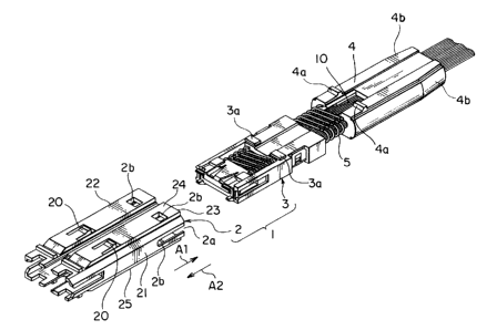
Referring to Figs. 1 and 2, an optical connector 1 according to an
embodiment of this invention will be described.
The optical connector 1 is for use in connecting an optical fiber 10.
The optical fiber 10 has a ribbon-like shape and comprises a number of fiber
wires arranged in parallel to one another and bonded to one another in the
manner known in the art. Although the optical fiber 10 has a size very short
for
convenience of illustrating, the size is usually designed to be longer than
that in
Fig 1.
The optical connector 1 comprises a shell member (plug frame) 2, an
internal member 3 received in the shell member 2, a stopper 4 engaged with the
shell member 2, and a coil spring 5 interposed between the internal member 3
and the stopper 4. With respect to the shell member 2, the internal member 3
is movable in a first direction A1 while the movement in a second direction A2
opposite to the first direction A1 is inhibited or locked by engagement
between a
plurality of protrusions 3a and a plurality of locking members 20 which will
later
be described. Herein, the second direction A2 is a direction in which the
optical connector 1 is connected to a mating optical connector.
CA 02503690 2005-04-04
The shell member 2 is made of a synthetic resin and is elastically
deformable. The shell member 2 comprises first and second wall portions 21
and 22 faced to each other in a transversal direction perpendicular to the
first
and the second directions A1 and A2. Each of the first and the second wall
portions 21 and 22 is provided with a slit 2a. The slit 2a extends in the
second
direction A2 from an end face of the shell member 2 which faces the first
direction A1, i.e., a specific end face 23.
The shell member 2 further comprises third and fourth wall portions 24
and 25 connecting the first and the second waN portions 21 and 22 and faced to
each other in a vertical direction. Each of the third and the fourth wall
portions
24 and 25 is provided with a plurality of window portions 2b formed in the
vicinity of the specific end face 23. As will later be described, the window
portions 2b serve as an engaging portion to be engaged with the stopper 4.
The stopper 4 has a cylindrical shape with a through hole allowing the
optical fiber 10 to be inserted therethrough. The stopper 4 has a trapezoidal
shape in a top view and a rectangular shape in a side view. The optical fiber
is extracted from the internal member 3 through the through hole of the
stopper 4 in the first direction A1. Thus, the stopper 4 is slidable with
respect
to the optical fiber 10.
The stopper 4 has a plurality of lock portions or protruding portions 4a
to be fitted to the window portions 2b of the shell member 2 in one-to-one
correspondence. When the protruding portions 4a are fitted to the window
portions 2b, the stopper 4 is engaged with the shell member 2 in the first
direction A1. In the state where the stopper 4 is engaged with the shell
member 2, the coil spring 5 is compressed and urges the internal member 3 in
the first direction A1. Thus, the coil spring 5 is a compression coil spring
surrounding the optical fiber 10. The stopper 4 has a pair of tapered surfaces
4b defining a tapered portion therebetween which is formed in the vicinity of
an
CA 02503690 2005-04-04
6
end face facing the first direction A1 and gradually reduced in width. The
optical connector 1 is used in an assembled state where the internal member 3
is received in the shell member 2 and the stopper 4 is engaged with the shell
member 2. If the silts 2a are enlarged and opened, a part of the shell member
2 adjacent to the specific end face 23 is warped outward so that the window
portions 2b are released from the protruding portions 4a. Consequently, the
stopper 4 is forced out in the first direction A1 by an urging force of the
coil
spring 5. Accordingly, the protruding portions 4a are exposed outside the
shell
member 2 and can not be engaged with the window portions 2b. In this state,
the internal member 3 and the stopper 4 can easily be pulled out from the
shell
member 2 in the first direction A1. Thus, the optical connector 1 can be
disassembled into the shell member 2, the internal member 3, the stopper 4,
and the coil spring 5. The slits 2a may be understood as a release operation
portion.
Next referring to Figs. 1 and 3, description will be made of a
disassembling tool 11 according to the embodiment of this invention. In Fig.
1,
the disassembling tool 11 is faced to the optical connector 1.
The disassembling tool 11 is adapted to disassemble the optical
connector 1 mentioned above and comprises a tool body 12 and a pair of finger
portions 14 extending from the tool body 12 in the first direction A1 in
parallel to
each other. Each of the finger portions 14 is removably coupled to each of
opposite side surfaces of the tool body 12 by two screws 13. Thus, the screws
13 serve as a coupling structure.
The finger portions 14 have extending ends 14a in the second direction
A2 and confronting surfaces 14b faced to each other in a third direction A3
perpendicular to the first and the second directions A1 and A2. Each of the
finger portions 14 has a pair of adjacent surfaces 14c which are adjacent to
the
confronting surface 14b and are opposite to each other in a fourth direction
A4
CA 02503690 2005-04-04
7
perpendicular to the second and the third directions A2 and A3. Each of the
adjacent surfaces 14c of each finger portion 14 has a slant surface 14d
inclined
to reduce the thickness of the finger portion 14 in the forth direction
towards the
extending end 14a. As will later be described, the slant surface 14a serves as
a disengaging portion for disengaging the shell member 2 and the stopper 4 by
enlarging and opening the slit 2a. The slant surface 14d may be formed on
only one of the adjacent surfaces 14c.
The confronting surface 14b of each finger portion 14 is provided with a
groove 15 extending from the extending end 14a in the first direction A1 and
adapted to receive a part of the optical connector 1, i.e., the stopper 4. The
groove 15 on the confronting surface 14b of each finger portion 14 has a
bottom
including a parallel portion 15a extending from the extending end 14a in
parallel
to the first direction A1 and a sloped portion 15b extending from the parallel
portion 15a and inclined in a direction towards the other finger portion 14.
Next, description will be made of a method of using the disassembling
tool 11.
Referring to Figs. 4A and 4B; a first step of disassembling the optical
connector 1 will be described. The stopper 4 of the optical connector 1 is
inserted into a space 16 between the finger portions 14. At this time, left
and
right ends of the stopper 4 are inserted into the grooves 15 of the finger
portion
14. The optical fiber 10 is arranged along a guide surface 17 inclined in a
direction same as that of the slant surfaces 14d. More particularly, the guide
surface 17 is inclined parallel to the slant surfaces 14d. Furthermore, the
extending ends 14a of the finger portions 14 are positioned at entrances of
the
slits 2a of the shell member 2, respectively.
Next referring to Figs. 5A and 5B, a second step will be described.
The extending ends 14a of the finger portions 14 are forced into the slits 2a
of
the shell member 2. Then, the slits 2a are enlarged and opened so that the
CA 02503690 2005-04-04
part of the shell member 2 adjacent to the specific end face 23 is warped
outward. In this event, the window portions 2b are disengaged from the
protruding portions 4a. Consequently, by the urging force of the coil spring 5
(see Fig. 2), the stopper 4 is forced out in the first direction A1. The
stopper 4
is guided by the grooves 15 to move in the first direction A1 and is stopped
at a
position where the tapered surface 4b meets the sloped portions 15b.
Referring to Figs. 6A and 6B, a third step will be described. The
optical fiber 10, the disassembling tool 11, and the stopper 4 are pulled by
fingers. Then, the internal member 3 is pulled out from the shell member 2 as
illustrated in the figures. Thus, the optical connector 1 is disassembled into
the
shell member 2 and other parts.
While the present invention has thus far been described in connection
with a preferred embodiment thereof, it will readily be possible for those
skilled
in the art to put this invention into practice in various other manners.