Note: Descriptions are shown in the official language in which they were submitted.
CA 02503772 2005-O1-19
WO 20041079287 PCTIEP20041001025
1
Blank Cartridge Device with Muzzle Flash Suppressor
The invention relates to a blank cartridge device for attachment over a muzzle
flash suppressor, whereby
- the muzzle flash suppressor has a longitudinal bare hole on the end facing
the
barrel muzzle for unobstructed penetration and a central inner cone, whereby
lateral openings are provided between this inner cone and the muzzle of the
muzzle flash suppressor for gas escape, and
- the blank cartridge device has a centrally arranged tube that penetrates the
bore hole of the muzzle flash suppressor and is provided with a flat external
cone
on its rear end, which sits sealed on the inner cone of the muzzle flash
suppressor, whereby the tube has a core bore hole that lengthens the barrel,
the
front end of which is locked and forms a backstop,
- a cover is provided, which radially circumvents the lateral openings of the
muzzle flash suppressor on the outside, and
- an injector bore hole is provided, which connects the interior of the core
bore
hole with the outside (preamble of claim 1 ).
While in most cases the muzzle flash suppressor must be unscrewed during the
use of a blank cartridge device and can thus be lost (e.g. with G3), the blank
cartridge device in accordance with the invention is pushed onto the muzzle
flash
suppressor and is attached to it (see DE 197 29 565 C2). A cross pin that
reaches behind the muzzle flash suppressor is provided as mounting device for
the known
CA 02503772 2005-O1-19
WO 20041079287 PCT/EP2004/00~ 025
2
blank cartridge device. This cross pin lies in the field of vision of the
shooter so
that he can always be assured of the proper fit of the blank cartridge device.
However, it turns out that this mount is not secure in the case of inattention
on
the part of the shooter or during the night. If the mount is not fully
engaged, it can
happen that the blank cartridge device flies off during firing. This danger is
particularly high when a round of live ammunition is shot by accident and
needs
to be caught by the blank cartridge device.
Moreover, there are weapons in which the outside diameter of the muzzle flash
suppressor does not exceed that of the barrel or exceeds it only slightly; the
known blank cartridge device could not be mounted on this type of weapon.
Incidentally, we always assume the horizontal weapon in the firing position
when
expressions like e.g. "above" are used, whereby "in front" points in the
direction
of fire.
Based on the above problem situation, the object of the invention is to
further
develop the known blank cartridge device such that a flying away of the
improperly attached blank cartridge device is prevented.
This problem is solved with the blank cartridge device according to the
invention
in that
- the injector bore hole sits in a constriction of the core bore hole,
- the part of the core bore hole turned away from the barrel is connected with
the
outside via at feast a generously measured radial bore hole, and
CA 02503772 2005-O1-19
WO 20041079287 PCTIEP2004/001025
3
- the tube has an external thread that engages with an internal thread in the
bare
hole of the muzzle flash suppressor (claim 1 ).
If the thread is tightened then both of the cone seats are compressed together
in
a sealing manner; with an appropriate design, these cone seats that engage
with
each other are self-closing so that they cannot unscrew themselves. However,
should the thread not be tightened enough, gas escapes through the gap
between the cone seats that are only loosely seated on top of each other. The
thread still continues to prevent a loosening of the blank cartridge device
from the
muzzle flash suppressor. The powder gases do not just escape through the
injector bore hole, but rather mainly through the gap between the loosely
fitted
cone seats. Therefore, the weapon can no longer be loaded through. This tells
the shooter that something is wrong. This then prompts the shooter to examine
the blank cartridge device and he will see when turning the tube that his
thread is
not tightened sufficiently.
The situation with an accidentally emitted live shot is more difficult when
the
thread is not completely screwed down at the same time. Indeed, modern
weapons cartridges (e.g. .223) only have less than half of the muzzle energy
of
earlier weapons cartridges (e.g. 30-06); nonetheless, the impact could still
possibly be enough to warp and thus loosen the thread. But, the constriction,
in
which the injector bore hole is located, does not stop the shot, but rather
only
brakes it. The duration of the impact of the shot against the blank cartridge
device is thereby lengthened. Contrary to expectation, the thread withstands
this
CA 02503772 2005-O1-19
WO 20041079287 PCT/EP20041001025
4
lengthened impact even if it is not tightened properly and thus does not use
the
full length of the thread.
The first projectile that is absorbed by the blank cartridge device presses
both
parts of the thread together tightly, whereby possible tolerances are
cancelled.
Now, the thread connection is also in the position to withstand stress from
further
projectiles.
The muzzle flash suppressor works like an attenuator based on its spring
capability so that the thread, with which this muzzle flash suppressor is
attached
to the barrel of the weapon, is not damaged in any way. Only the blank
cartridge
device is damaged when absorbing a live shot, perhaps also the muzzle flash
suppressor but in no way the weapon itself. This also applies to a short
burst.
Thus, each blank cartridge device in accordance with the invention is attached
to
each adjusted muzzle flash suppressor regardless whether or not it is attached
to
the weapon. At the same time, the thread connection between the muzzle flash
suppressor and the blank cartridge device ensures that it cannot fly off on
its own
when it is insufficiently attached.
A further embodiment of the blank cartridge device consists in that the
constriction sits outside of the muzzle flash suppressor (claim 2). Thus,
damage
to the muzzle flash suppressor is avoided if the tube should expand due to the
impact of a shot on the constriction with the injector bore hole. Damage to
the
weapon is thus minimized in the case of a blank accident.
CA 02503772 2005-O1-19
WO 2004/079287 PCTIEP2004/001025
Another version of the blank cartridge device consists in that the tube is
inserted
into a stop block on the muzzle side that lengthens the core bore hole (claim
3).
The tube and the stop block can thereby be optimized depending on the
different
conditions, e.g. an especially ductile material for the tube and a
particularly hard
material for the stop block.
Preferably, the core bore hole has at least a caliber size in the back, but
can
narrow towards the front (claim 4). Thus, at least at first, the projectile
does not
grind uncontrollably on the wall of the core bore hole, but rather is first
warped on
the constriction and this in a controlled manner. Furthermore, abrasion damage
is prevented after it passes the radial bore hole. Thus, the controlled
absorption
of several shots is possible.
According to a further embodiment of the invention, the blank cartridge device
is
enhanced by the fact that the stop block is extended towards the back and
rests
at least in a sealed manner against the back side of the muzzle flash
suppressor
and that radial discharge openings are provided in this extension and are
connected with the gas outlet openings (claim 5). A gas chamber is thus
created
between the gas outlet openings of the muzzle flash suppressor and the
extension of the stop block.
The (at least) one radial bore hole preferably discharges under the extension
of
the stop block and is connected with radial openings in it, especially with
the
radial discharge openings (claim 6). These radial discharge openings do not
necessarily need to discharge to the outside, but rather preferably discharge
into
the gas outlet openings of the muzzle flash suppressor, into which the gas
flow
also enters, which flows through the cone seat when the blank cartridge device
is
not properly tightened. The purpose of this measure is to deflect as often as
possible the gas flow in
CA 02503772 2005-O1-19
WO 2004/079287 PCTIEP20041001025
6
order to prevent with certainty the escape of solid particles from the blank
cartridge device. In the continuation, additional radial discharge openings
discharge to the outside again through the extension
Preferably, the radial openings, especially the radial discharge openings of
the
extension of the stop block, are encompassed by an exterior radial deflection
sleeve that is mainly open only towards the front (claim 7). Thus, the escape
of
the gases of the blank cartridges takes place towards the front, as with a
live
cartridge. However, another deflection takes place and thus also sufficient
guarantee for inadequately tightened blank devices or when a live cartridge is
fired.
Overall, the blank cartridge device in accordance with the invention and the
muzzle flash suppressor in accordance with the invention form a simple device
that is small in size. It does not overlap the muzzle flash suppressor towards
the
back, has a small outer diameter and remains on the muzzle flash suppressor
even when insufficiently tightened, whereby gas escape takes place at the
other
location and a reloading of the weapon is stopped. At the same time, the
firing of
a live cartridge is possible when the blank cartridge device is attached,
without
the weapon being damaged and without particles from the shot making their way
outside.
The object of the invention is described in greater detail in an example based
on
the included schematic drawing, but it is not intended to be restrictive in
any way.
The drawing shows the following:
Fig. 1 the view of a blank cartridge device that is screwed together with a
muzzle
fire silencer
CA 02503772 2005-O1-19
WO 2004/079287 PCT/EP2004/001025
7
Fig. 2 a longitudinal section of the muzzle flash suppressors with an
installed
and ready-to-use blank cartridge device, and
Fig. 3 a schematic view of a longitudinal section as in Fig. 2, but after the
firing of
three live cartridges.
All figures show the same embodiment; thus, the reference numbers for all
parts
are the same, provided that they are not changed by the shooting of a live
cartridge. If reference numbers have been omitted from elements for the sake
of
better clarity, the reference numbers from the other figures still apply.
Figure 1 shows the front part of a rapid fire gun 1, which has a hand guard
49,
from which a barrel 47 projects towards the front. A muzzle flash suppressor
35
is tightened onto the front end of the barrel 47 such that it cannot be
loosened
without aid of workshop tools. The tube 19 of a blank cartridge device 3 is
screwed into the muzzle flash suppressor 35. An annular gap 17 forms the
outlet
opening for the power gas towards the front.
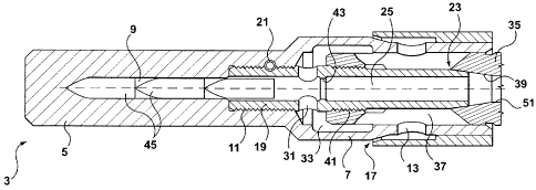
Figure 3 shows the structure of muzzle flash suppressor 35 and blank cartridge
device 3.
The muzzle flash suppressor 35 has a penetrating over-caliber bore hole 51,
which extends from the muzzle of the barrel 47 over a short, cylindrical
section
that fades into an inner cone 39, expands from this and extends in a mainly
cylindrical fashion to the firing opening. A fine internal thread is
CA 02503772 2005-O1-19
WO 2004/079287 PCTIEP2004/001025
8
arranged in front of the firing opening and forms the female end of the thread
connection 41. Longish gas outlet openings 37 extending towards the outside,
which connect the bore hole 51 with the area radially outside of the muzzle
flash
suppressor, are arranged between the inner cone 39 and the inner thread 41.
These gas outlet openings 37 are customary. The exterior surface of the muzzle
flash suppressor is cylindrical.
With a normal, live shot, when the blank cartridge device 3 is not attached to
the
muzzle flash suppressor 35, a portion of the firing gas is allowed to escape
to the
gas outlet openings 37, while the projectile flies through bore hole 51. These
gases then do not disrupt the flight of the shot, the glare from the muzzle
fire is
reduced and the firing noise can be located less precisely.
The blank cartridge device 3 is made up of three parts: the center tube 19, a
stop
block 5 and an outer sleeve 15
The tube 19 fits into the bore hole 51 of the muzzle flash suppressor and has
on
its back end an outer cone 23, which fits exactly with the inner cone 39 of
the
muzzle flash suppressor 35 and forms together with it a tight cone seat
preventing the independent relative rotation between tube 19 and muzzle flash
suppressor 35.
The tube 19 also has two external threads that make a thread connection 41
with
the muzzle flash suppressor 35. These external threads are fine threads.
CA 02503772 2005-O1-19
WO 20041079287 PCT/EP2004/001025
9
The tube 19 is screwed into an internal thread tapped blind hole in stop block
5
until the front end of the tube 19 sits tightly on the floor of the tapped
blind hole.
Then the thread connection 11 is guaranteed by a diagonal spring pin 21. Tube
19 and stop block 5 now form one unit.
The tube 19 is now screwed into the muzzle flash suppressor until the cone
seat
between the inner cone 39 and the outer cone 23 of the muzzle flash suppressor
35 and the tube 19 is created. Now the external thread of the thread
connection
41 is completely seated in its internal thread.
The tube 19 is penetrated by a central core bore hole 25, which has more than
a
caliber diameter and is mainly cylindrical, apart from a constriction 27,
which sits
just in front of the front end of the muzzle flash suppressor 35 or in front
of the
external thread of the thread connection 41 and locally constricts the core
bore
hole except for an injector bore hole 29. The constriction 27 hereby forms a
narrow cross web, while the diameter of the injector bore hole 29 regulates
the
afflux of the combustion gases in the barrel 47, which is required for the
reloading of the weapon 1 when using blank cartridges.
Two large, opposite-lying radial bore holes 31 are provided between the
constriction 27 and the external thread of the thread connection 11 and
penetrate
the wall of the tube 19. All combustion gases that end up in the care bore
hole 25
leave it through the radial bore holes 31.
In the front part of the stop block 5, the core bore hole 25 continues in the
center
core bore hole 9 with the same diameter and forms a tapped blind hole.
CA 02503772 2005-O1-19
WO 2004/079287 PCT/EP2004/001025
The stop block 5 continues towards the back as one piece through a tubular
extension 7, the mainly cylindrical inner diameter of which is approximately
similar to the outer diameter of the front part of the stop block. This inner
diameter mainly sits sealed on the center and the back part of the cylindrical
outer surface of the muzzle flash suppressor 35. Expansion space 33, which is
formed by an expansion of the inner diameter of the extension 7, is created
between this sealed support and the front part of the extension 7. This
expansion
space connects the radial bore holes 31 with the gas outlet openings 37 of the
muzzle flash suppressor 35.
The back part of the extension 7, which sits sealed on the outer surface of
the
muzzle flash suppressor 35, has, in turn, a crown of gas outlet openings 13,
which radially connect the gas outlet openings 37 with the outside of the
extension 7. In this manner, the combustion gases flow through the gas outlet
openings 37 and then the gas outlet openings 17 for properly mounted blank
cartridge device 3 as well as for insufficiently tightened blank cartridge
device 3
as they flow through the loose cone seat 23, 39.
The sleeve 15 is sealed on the back side of the outside of the extension 7,
for
instance through shrink-fitting or welding. This sleeve 15 has a displaced
inner
bore hole, the back part of which has a smaller diameter and sits on the outer
surface of extension 7, while the front part has a larger diameter and is
spaced
somewhat away from the outer surface of the extension 7. This front part
covers
CA 02503772 2005-O1-19
WO 2004/079287 PCT/EP2004/001025
11
by far the gas outlet openings 13, is spaced somewhat away from the outer
surface on its front end and hereby forms the annular gap 17. This annular gap
is
the forward-turned gas outlet opening of the blank cartridge device 3.
Up to the annular gap, the inner surface of the sleeve 15 is tapered towards
the
outside, while the outside surface of the extension 7 expands there conically.
The
gases hereby escape forward and outward, so that excess soiling of the free
outer surface of the blank cartridge device 3 is prevented.
Figure 3 shows the blank cartridge device 3 described just now after the
firing of
three live cartridges.
As can be seen, the constriction 27 with the injector opening 29 was more or
less
sheared off by a shot 45, so that instead a free passageway 43 was created.
But
the core bore holes 9, 25 were not or only slightly enlarged. Three such
projectiles 45, which were caught, sit in the front core bore hole 9, which
represents a tapped blind hole in the stop block. These projectiles are only
represented schematically; in reality, they form one single compressed block.
The materials for stop block 5, tube 19 and sleeve 15 are selected such that
they
optimally correspond with the respective purpose. For example, the tube is
strong but ductile, whereby due to the comparatively low resistance with which
the constriction 27 opposes a projectile 45 and due to the at least caliber-
size
core bore file 25, tube 19 is mainly stressed when a live cartridge is
accidentally
fired.
CA 02503772 2005-O1-19
WO 20041079287 PCT/EP2004/001025
12
On the other hand, stop block 5 is strong and hard so that it can never be
penetrated. The material of sleeve 15 is basically the same as tube 19.