Note: Descriptions are shown in the official language in which they were submitted.
CA 02503788 2005-04-26
WO 2004/039544 PCT/IT2003/000662
Sharpening unit and cutting machine comprising at least one blade and said
sharpening
unit
Descri tp ion
Technical Field
The present invention relates to a cutting machine for cutting elongated
products,
such as and in particular logs of web material for the production of small
rolls destined for
packaging and sale.
More specifically, the invention relates to a cutting machine with at least a
cutting
blade and at least a sharpening unit associated with said cutting blade.
The invention also relates to a sharpening unit for cutting machines or other
machines provided with a blade that must be constantly or periodically
sharpened.
State of the Art
In the paper converting industry rolls or logs of substantial axial length are
produced by v winding a predetermined quantity of paper, for example tissue
paper, to
subsequently produce small rolls of toilet tissue, kitchen towels and the
like. For this
purpose the logs are cut orthogonal to their axis and divided into a plurality
of small rolls
of a suitable length, which are then packaged for distribution and sale. The
logs are cut by
means of special "cutting" machines, which have one or more cutting blades and
one or
more sharpening units for each blade.
2 0 Analogous requirements are found in other technological sectors, where it
is
necessary to cut an elongated product into smaller portions, in particular
logs of wound
web material.
US-A-3,213,731 describes a cutting machine for logs of web material, wherein a
disk-shaped blade rotates about its axis supported by a unit in turn rotating
about a
2 5 principal axis parallel to the direction of feed of the logs to be cut,
which are fed along a
feed path towards the cutting area.
An analogous cutting machine, but with two disk-shaped cutting blades, is
described in US-1ZE-30,598. In this case the axis of rotation of each disk-
shaped blade is
parallel to the axis of the logs to be cut, but skew in respect of the
principal axis of rotation
3 0 of the unit carrying the blades, to obtain a component of motion of the
blade in a direction
parallel to the direction of feed of the logs to be cut, so that these can
advance with
continuous movement at constant speed. A sharpening unit with two sharpening
grinding
wheels for each blade periodically sharpens the respective blade that loses
its cutting edge.
EP-A-507750 describes a cutting machine whexein the rotating unit carrying the
CA 02503788 2005-04-26
WO 2004/039544 PCT/IT2003/000662
disk-shaped blades) is provided with alternate translatory movement to allow
the logs to
be cut to move forwards with continuous movement. The feed speed of the logs
is variable
and not constant, to obtain a series of advantages in terms of flexibility and
reduction in
stresses and in the overall dimensions of the machine. In this case too a
sharpening unit is
provided, with two grinding wheels to restore the cutting edge of the blades
EP-A-609668 describes a cutting machine with a rotating unit carrying two disk-
shaped blades rotating about respective axes parallel to the logs to be cut,
but skew in
respect of the axis of rotation of the rotating unit. The logs are fed at a
variable speed as in
EP-A-507750 to obtain the same advantages of flexibility.
EP-A-0555190 describes a cutting machine with a helical cutting blade and a
sharpening unit with two grinding wheels.
US-A-5,038,647 describes a cutting machine that uses a band blade rather than
a
disk-shaped blade, particularly suitable for cutting rolls with a large
diameter. Two
sharpening units with different functions are associated with the blade. A
first sharpening
unit, with motorized grinding wheels, produces and sharpens the principal
bevel of the
blade, while a second unit with idle grinding wheels keeps a counter-bevel or
secondary
bevel sharpened.
WO-A-0136151 describes a sharpening unit for the blade of a cutting machine,
with tools to dress the grinding wheels.
2 0 In prior art machines the grinding wheels are carried by a grinding wheel
unit that
is gradually moved towards the blade to be sharpened in order to offset the
reduction in
diameter (in the case of disk-shaped or helical blades) or in width (in the
case of band
blades) due to wear caused by repeated sharpening operations. The movement
towards the
blade is set by the operator normally as a function of the number of
sharpenings performed
2 5 on the blade. In other words, the grinding wheel unit is moved towards the
blade by a
predetermined extent after a predefined number of sharpening operations,
assuming that
this corresponds to a wear and thus a reduction in the dimension of the blade
that are
always constant. The movement towards the blade is calculated so that contact
is always
guaranteed with sufficient pressure of the grinding wheel on the blade, even
if there should
3 0 accidentally be more wear than expected. This means that there is often
more pressure of
the grinding wheels on the blade than necessary and consequently also
excessive wear on
the blade. On the contrary, there may be insufficient sharpening pressure,
caused by the
blade and the grinding wheels not having been moved close enough together. In
this case
sharpening is not performed efficaciously.
CA 02503788 2005-04-26
WO 2004/039544 PCT/IT2003/000662
-3-
Moreover, due to the rigidity of the grinding wheel unit the pressure with
which the
two grinding wheels operate on the two sides of the blade is not equal, due to
unavoidable
errors in positioning, tolerances and any uneven wear on the grinding wheels.
Objects and suirnnary of the invention
The object of the present invention is to provide a sharpening unit, in
particular
although not exclusively for cutting machines to cut elongated products, which
allows
more efficient sharpening in respect of prior art sharpening units.
Another object of the invention is to provide a cutting machine to cut
products,
especially although not exclusively logs of web material, comprising at least
one
particularly efficient sharpening unit and which on the one hand sharpens the
blades
accurately and on the other causes limited wear on the blade(s).
For this object, according to a first aspect of the present invention, a
sharpening unit
is provided comprising a grinding wheel unit with at least two opposed
grinding wheels to
act on two sides of a blade, characterized in that said grinding wheel unit is
equipped with
at least a degree of freedom to center the grinding wheels in respect of a
lying surface of
the portion of the cutting edge of the blade on which the grinding wheels act.
This allows a
balanced and uniform sharpening action on the two sides of the blade.
Moreover, when the
grinding wheel unit is equipped with a movement towards the blade to recover
any
decreases in the dimension of the blade caused by wear, with self centering of
the grinding
2 0 wheels the pressure exerted can be controlled more accurately, avoiding
pressures and thus
excessive wear.
The blade can be a flat disk-shaped blade, in which case centering is
performed in
practice in respect of a lying plane of the cutting edge. However, the blade
can also have
other forms, for example it can extend helically with a corresponding helical
form of the
2 5 cutting edge. In this case centering of the two grinding wheels takes
place in respect of the
lying surface of the portion of cutting edge or cutting bevel of the blade on
which the
grinding wheels are temporarily acting and this surface can vary according to
the position
of the grinding wheels along the blade. In the case of band blade, the lying
surface of the
cutting edge, in respect of which the grinding wheels are centered, is a plane
parallel to the
3 0 portion of the band forming the blade on which the area of the cutting
edge is found that is
instantaneously sharpened.
A further aspect of the present invention relates to a cutting machine for
cutting
elongated products, comprising: at least one path for the products to be cut;
at least one
device to feed the products along said path; at least one blade provided with
a cutting
CA 02503788 2005-04-26
WO 2004/039544 PCT/IT2003/000662
-4-
movement to cut said products; at least one sharpening unit for said blade,
which
comprises a grinding wheel unit with at least two opposed grinding wheels to
act on two
sides of said blade. According to the invention, the machine is characterized
in that the
grinding wheel unit is provided with at least a degree of freedom to center
the grinding
wheels in respect of a lying surface of the portion of the cutting edge, that
is of the cutting
bevel of the blade on which the grinding wheels act. The grinding wheel unit
can be taken
to a fixed position in respect of the blade, when the dimensions of the latter
vary slightly
due to wear and sand wear can be recovered for example by moving the grinding
wheels
towards the blade without also moving the grinding wheel unit. Nonetheless,
the
sharpening unit normally comprises a system to move the grinding wheel unit
towards the
blade along a direction of forward movement, to recover wear on the blade. In
this case,
self centering of the grinding wheels is particularly important and
advantageous as it
prevents the onset of excessive sharpexiixig pressures, or - on the contrary -
conditions of
insufficient pressure and thus insufficient sharpening.
According to a particular embodiment, the grinding wheel unit is provided with
a
further degree of freedom, partly restricted, to center the grinding wheels in
respect of the
blade. Partly restricted degree of freedom is intended as possible movement
restricted, for
example, through the effect of a return spring and/or an actuator that limits
the freedom of
movement of the grinding wheel unit according to this degree of freedom. For
example, the
2 0 grinding wheel unit is free to move in one direction; but its movement is
limited in the
other direction, or the movement is contrasted by a return spring. This
guarantees that the
movement according to this further degree of freedom always brings the
grinding wheels
into contact with the blade to be sharpened, preventing movement away from the
cutting
edge.
2 5 According to an advantageous embodiment, this second degree of limited or
restricted freedom is represented by the fact that the grinding wheel unit can
rotate or
oscillate about an axis of oscillation. In this way the grinding wheel unit
revolves about an
axis of oscillation disposed generically in an intermediate position between
the axes of
rotation of the grinding wheels and in substance lying on the lying plane of
the portion of
3 0 cutting edge on which the grinding wheels acts. When the blade has a
cutting edge that
does not lie on the plane but on a lying surface of a different shape, such as
the case of a
helical blade, the axis of oscillation can lie on a plane that approximates
the lying surface
of said portion of cutting edge.
The grinding wheels are generally disposed with their respective axes of
rotation
CA 02503788 2005-04-26
WO 2004/039544 PCT/IT2003/000662
-5-
skew. According to a preferred embodiment of the invention, the axis of
oscillation of the
grinding wheel is advantageously disposed in a position of minimum distance
between said
axes of rotation. In practice, the axis of oscillation can also be the axis of
symmetry of the
grinding wheels, i.e. these are disposed in a substantially symmetrical way in
respect of the
axis of oscillation. The movement of the grinding wheel unit about the axis of
oscillation
must be restricted, so that the grinding wheels are effectively stressed to
come into contact
with the blade to be sharpened, rather than fending to move to a non-operating
position.
For this purpose an elastic return element, an actuator element or another
device or means
to control the pressure may be provided with which the grinding wheels are
pushed against
the blade. In substance, therefore, oscillation of the grinding wheel unit
represents a further
degree of freedom in the movement of the grinding wheel unit, although this
movement is
not strictly completely free, but restricted so that it takes place in the
direction that brings
the grinding wheels effectively into the operating position against the blade.
The axis of oscillation of the grinding wheel unit may be essentially parallel
to the
direction of feed of the grinding wheel unit in respect of the blade and be
essentially
orthogonal to the direction of feed of the products to be cut towards the
blade.
According to a further particularly advantageous characteristic of a possible
embodiment of the invention, the grinding wheel unit is free to translate
along a direction
of translation not parallel to the lying plane of the blade, to center the
grinding wheel in
2 0 respect of the lying plane, that is the median plane of the blade. The
direction of translation
is in practice essentially orthogonal to the lying plane of the blade and
preferably
approximately substantially parallel to the direction of feed of the products
to be cut. The
axis of oscillation of the grinding wheel unit is therefore advantageously
orthogonal to the
direction of translation of the unit. According to this preferred embodiment
of the
2 5 invention, therefore, the grinding wheel unit has a first degree of
freedom consisting in the
fact that it can translate in the direction of translation, and a second
degree of freedom
consisting in the fact that it can oscillate about the axis of oscillation,
the latter movement
being limited or restricted in the manner and for the reasons explained above.
The machine according to the invention may have one or more blades. Moreover,
a
3 0 single sharpening unit or even more than one sharpening units may be
associated with the
blade or with each blade. In this case the two or more sharpening units
advantageously
have different characteristics and functions. For example, a first unit can
have motorized
grinding wheels to sharpen the principal bevel of the blade and the second can
have idle
grinding wheels to sharpen the counter-bevel of the blade. The grinding wheels
of the two
CA 02503788 2005-04-26
WO 2004/039544 PCT/IT2003/000662
-6-
units can typically have different inclinations. One blade that has two
sharpening units to
sharpen bevel and counter-bevel (or secondary bevel) is described in US-A-
5,038,647. In
the case of a blade with a single sharpening unit, this may have motorized
grinding wheels
or idle grinding wheels, which are drawn in rotation by frictional force with
the blade.
Further advantageous features and embodiments of the invention are set forth
in the
appended dependent claims, and shall be described hereunder with reference to
some
examples of embodiment.
Brief description of the drawing
The invention shall be better understood by following the description and the
accompanying drawing, showing non-limiting practical embodiments of the
invention.
More specifically, in the drawing:
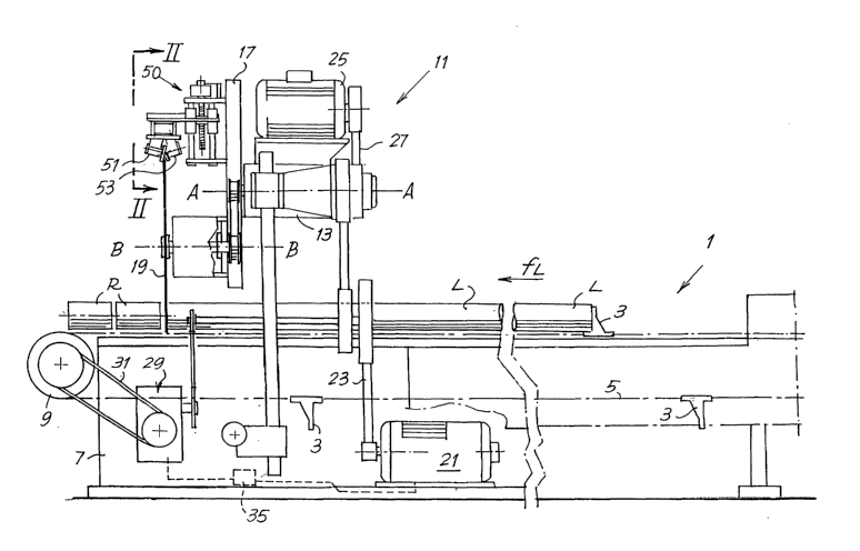
Figure 1 shows a schematic side view of a cutting machine for cutting rolls of
web
material, with a rotating unit carrying a disk-shaped blade, to which a
sharpening unit
according to the present invention is applied;
Figure 2 shows a front view and partial section of the sharpening unit in a
first
embodiment, according to II-II in Figures 1 and 3;
Figure 3 shows a side view and partial section according to III-III in Figure
2;
Figure 4 shows a plan view according to IV-IV in Figure 2;
Figure 5 shows a partial side view of a sharpening unit in a different
embodiment;
2 0 Figure 6 shows a plan view according to VI-VI in Figure 5; and
Figure 7 shows a section according to VII-VII in Figure 5.
Detailed description of the preferred embodiments of the invention
Figure 1 schematically shows a cutting machine according to the present
invention.
In this case it is a cutting machine for rolls of paper or other wound web
material, wherein
~ 5 the cut is performed by a disk-shaped blade rotating about its axis,
carried by a unit in turn
rotating about a principal axis of rotation, parallel or approximately
parallel to the direction
of feed of the rolls to be cut. Advantageously, a sharpening unit of the type
shown in
Figures 5 to 7 with motorized grinding wheels is applied to a machine of this
type.
However, a sharpening unit with idle grinding wheels, of the type shown in
Figures 2 to 4,
3 0 may be applied (if need be in combination with or alternatively to it).
The sharpening units,
which shall be described hereunder with particular reference to Figures 2 to
7, may also be
applied to different machines, such as cutting machines with a helical blade
or with a band
blade. It must therefore be understood that the machine shown in Figure 1 must
be
intended purely as an example of a possible machine to which sharpening units
according
CA 02503788 2005-04-26
WO 2004/039544 PCT/IT2003/000662
_7_
to the present invention may be applied.
Moreover, the sharpening grinding wheels of the unit shown in Figures 2 to 4
may
also be motorized grinding wheels and, on the contrary, the grinding wheels of
the
sharpening unit shown in Figures 5 to 7 may be idle grinding wheels.
Figure 1 schematically shows (limited to its front part) the cutting machine
as a
whole, indicated with 1. The machine has a feed path of the logs to be cut,
indicated with
L, which are pushed by pushers 3 secured to a flexible chain element or the
like 5~ driven
about driving wheels supported by a fixed structure 7. Only one driving wheel,
indicated
with 9, is visible in Figure 1, while the other is at the rear end of the
cutting machine, not
shown. In actual fact, as known from prior art, there may be more than one
flexible
element 5 in parallel to feed several rows of logs L according to parallel
paths.
The flexible elements 5 associated with the various parallel feed channels of
the
logs may be motorized separately from one another to stagger the movement of
logs in
each feed channel.
The number 11 generically indicates a cutting head that by means of a support
13
carries a rotating unit 17. The unit 17 rotates about a horizontal axis A-A
parallel to the
direction fL of feed of the logs L. In the example shown, a disk-shaped blade
19 is
mounted on the rotating unit 17, rotating about its own axis of rotation B-B
parallel to the
axis A-A and to the direction of feed fL of the logs L. Two or more disk-
shaped blades
2 0 rotating about their axes of rotation distributed about the axis A-A may
be provided on the
rotating unit 17. In a per se known way the rotating unit 17 can be equipped
with an
alternate translatory movement parallel to the direction fL, or the blade 19
can be provided
individually with this movement and in this case translate in respect of the
unit 17. In
either of these cases the logs may be fed with continuous rather than
intermittent
2 5 movement.
The number 21 indicates a motor that, by means of a belt 23, transmits
rotatory
motion to the rotating unit 17. A second motor 25 is positioned on the support
13 of the
rotating unit 17 and, by means of a belt 27, supplies rotatory motion to a
shaft that drives
the rotating disk-shaped blade 19 in rotation. By means of a belt 31, a third
motor 29 drives
3 0 the guiding wheel 9 of the continuous flexible element 5 in rotation. As
mentioned above,
as several parallel channels may be provided for feed of the logs L that are
cut separately
to form the small rolls R, a guiding wheel 9 may be associated with each
channel, with its
own motor unit 29 suitably controlled as a function of the angular position of
the rotating
unit 17. The number 35 indicates a programmable control unit that synchronizes
the
CA 02503788 2005-04-26
WO 2004/039544 PCT/IT2003/000662
-g_
forward movement of the flexible elernent(s) 5 through the motors) 29 with the
angular
position of the rotating unit 17 driven in rotation by the motor 21.
A sharpening unit generically indicated with 50 is disposed on the rotating
unit 17,
to sharpen the blade 19. The sharpening unit 50 has two grinding wheels 51 and
53, which
act on two sides of the cutting edge of the blade 19.
Figures 2 to 4 show a first embodiment of the sharpening unit 50. In this
embodiment idle grinding wheels are used, whichare drawn in rotation through
the effect
of the frictional force exerted during contact between each grinding wheel and
the blade
19. The sharpening unit 50 has a pair of plates 55, 57 secured to the rotating
unit 17 (or to
another part of the cutting machine if this does not have a rotating unit, for
example to the
supporting frame of a band blade). Between the two plates 55, 57 bars 59 with
a circular
section extend to form sliding guides for the same number of bushings 61. The
bushings
are integral with a carriage indicated as a whole with 63.
The carriage 63 moves along the guides formed by the bars 59 according to the
arrow f63 to move gradually against the axis B-B of the blade 19, in order to
hold the
grinding wheels in the operating position offsetting the decrease in dimension
of the blade
19 due to wear caused by sharpening.
Movement of the carriage 63 according to the arrow f63 is controlled by a free
wheel mechanism 65 keyed on a threaded bar 67 parallel to the guide bars 59. A
nut screw
2 0 69 integral with the carriage 63 engages with the threaded bar 67.
Rotation of the free
wheel mechanism 65 is controlled by a piston-cylinder actuator 71 with a short
stroke that
acts on a bracket 73 integral with the free wheel mechanism 65. The number 75
indicates a
return spring of the bracket 73. Each stroke to extend the actuator 71 causes
the threaded
bar 67 to rotate by an angular step and therefore a forward movement by a
controlled
2 5 extent in the direction of the arrow f63 of the carriage 63.
A cantilevered bracket 77 is integral with the carriage 63 and supports a pair
of
guides 79 essentially parallel to the axis B-B of the blade 19 and essentially
orthogonal to
the direction f63 of translation of the carriage 63. A slide 81 that supports
a grinding wheel
unit 80 is free to translate along the guides 79. A shaft 85 is supported idle
by bearings 83
3 0 inside the slide (see in particular Figure 2). The shaft 85 is free to
rotate about its axis C-C,
parallel to the axis of the threaded bar 67 and therefore to the direction f63
in which the
carriage 63 and the sharpening grinding wheels move against the blade 19.
Fixed to the bottom of the shaft 85 is a plate 87 that carries integrally
secured to it
two blocks 89 supporting the grinding wheels 51, 53. As shown in particular in
Figure 3
CA 02503788 2005-04-26
WO 2004/039544 PCT/IT2003/000662
-9-
for the grinding wheel 53, the grinding wheels are carried by spindles 91
supported idle by
bearings 93 in the blocks 89. Rotation of the grinding wheels is produced by
the frictional
force between them and the sides of the blade 19.
While the plate 81 is completely free to translate along a. direction of
translation
according to the double arrow f81 parallel to the guides 79, the plate 87
carried by the shaft
85 is. elastically stressed in a predetermined angular position (defined by a
stop
schematically indicated in Figure 2 with 88) by a pulling spring 95, the
ends~of which are
fixed on one side to the plate 87 and on the other to a suitable point of the
slide 81 (for
example in the point 90 indicated in Figure 3). Alternatively, the spring 95
could be
fastened to a fixed point in respect of the bracket 77. Coupling to the slide
87 is preferable
as in this case the stress of the spring does not tend to produce flexure of
the blade.
With this arrangement the grinding wheel unit 80 is provided with a degree of
freedom along the direction of translation f81 and with a degree of freedom
(limited by the
presence of the pulling springs 95) constituted by the fact that the plate 87
can rotate. The
grinding wheels 51, 53 integral with the grinding wheel unit 80 are thus
provided with a
double movement that allows them to be centered in respect of the lying plane
of the blade
19, that is the median plane of the blade, or in any case the lying plane of
the cutting bevel.
The first movement is a movement according to the guides 79 in a direction
orthogonal to
the lying plane of the blade and, therefore, in the layout of the machine in
Figure 1, parallel
2 0 to the direction fL of feed of the products L to be cut. The second
movement is an
oscillatory movement about the axis C-C orthogonal to the axis B-B of the
blade, and
therefore to the direction of feed of the products. As can be seen in
particular in Figures 2
and 3, the axis C-C lies on the median plane of the blade, or more generically
on the lying
plane of the cutting edge of the blade, in an intermediate position between
the two grinding
2 5 wheels 51, 53. More specifically, the axis C-C is in a barycentric
position in respect of the
axes A1-A1 and A2, A2 of the two grinding wheels 51, 53.
Thanks to this arrangement the grinding wheels can be centered on the blade 19
and
the pressure they exert on the blade can be controlled to prevent excessive
pressure. In fact,
when the grinding wheel unit 80 is moved, through the action of the free wheel
mechanism
3 0 65, according to the arrow f63, towards the axis B-B of the blade 19 by a
predetermined
extent, the grinding wheels 51, 53 react against the blade 19 which wedges in
the space
between the grinding wheels. Being free to translate with the slide 81 and the
plate 87
along the guides 79 according to the arrow f81, this movement takes the
grinding wheels
51, 53 to a position that is centered at all times in respect of the
centerline plane of the
CA 02503788 2005-04-26
WO 2004/039544 PCT/IT2003/000662
-10-
blade. At the same time, the fact that the grinding wheel unit can rotate the
grinding wheels
51, 53 about the axis C-C means that the two grinding wheels exert on the
blade the same
pressure, determined by the force of the pulling spring 95.
As the draw spring 95 extends by a very short extent as a result of the modest
oscillations of the grinding wheels about the axis C-C, it may be considered
that its traction
force is essentially constant and therefore the pressure exerted by the
grinding wheels on
the blade will also be essentially constant, irrespective of extent of the
angle of oscillation
about the axis C-C. Therefore, by setting a forward movement step along the
direction f63
approximate to the radial wear of the blade 19, even if the effective wear of
the blade is
10' less than estimated, thanks to the fact that the grinding wheels 51, 53
can be centered in
respect of the blade and to the presence of the pulling spring 95, essentially
the same
contact force can always be obtained between the grinding wheels and the blade
and
consequently the pressure strictly necessary to obtain sharpening is not
exceeded, thus
reducing wear on the blade and increasing its duration.
Instead of a spring 95 another system may be used to apply controlled stress
to the
plate 87 and to the grinding wheels 51, 53 about the axis C-C, for example a
piston-
cylinder actuator with a device to control stress.
Moreover, a position sensor may also be provided to detect the angular
position of
the plate 87 and of the grinding wheels 51, 53 to control forward movement of
the grinding
2 0 wheel unit 80 as a function of the wear on the blade. In fact, as the
blade becomes worn
and its diameter decreases, if the carriage 63 with the grinding wheel unit 80
does not
move forward along the direction f63, the decrease in diameter is offset with
rotation of the
plate 87 and therefore of the grinding wheels 51, 53 about the axis C-C.
Offset can be
obtained up to a certain point, beyond which the plate 87 meets the stop 88.
By detecting
2 5 the angular position of the plate 87 the carriage 63 can be moved forward
by a
predeterminable extent when the plate 87 has reached a predetermined angular
position, to
recover wear on the blade by forward movement of the carriage.
As in the example shown the unit 17 moves with an alternate translatory
movement
parallel to the axis A-A of rotation to allow continuous feed of the products
L to be cut, in
3 0 order to prevent the onset of inertial forces on the grinding-wheel unit
80 and on the slide
81 carrying it, which would tend to make the unit translate along the guides
79, a
counterweight can be secured to the slide 81 and restricted to move along the
direction of
the guides in the opposite direction to the direction in which the grinding-
wheel unit 80
and the slide 81 move. This arrangement is indicated with a dashed line and
schematically
CA 02503788 2005-04-26
WO 2004/039544 PCT/IT2003/000662
-11-
in Figure 3. The counterweight is indicated with 101. It is guided along
guides parallel to
the guides 79 and not shown and linked by a pinion 103 to a rack 105 integral
with the
slide 81. The pinion, supported idle about a fixed axis in respect of the
structure 77, also
meshes with a rack not shown integral with the counterweight 101. In this way
the inertial
forces applied simultaneously to the counterweight 101 and to the assembly
comprising the
grinding wheel unit 80 and the slide 81 cause no translation of these elements
along the
direction f81.
Moreover, to prevent accelerations deriving from the alternate movement of the
unit 17 from producing a torque on the grinding wheel unit 80 that tends to
make the unit
and therefore the grinding wheels 51 53 rotate about the axis C-C, the
grinding wheel unit
80 is dimensioned and balanced so that its center of gravity falls on the axis
C-C, or at least
so that the center of gravity of the elements free to rotate about this axis,
namely the shaft
85, the blocks 89, the plate 87 and the grinding wheels 51, 53, falls on it.
The device described with reference to Figures 2 to 4 is particularly suitable
to
produce a counter-bevel on the blade 19 or the like, for example a band blade.
In this case
the sharpening unit in question will be associated with another sharpening
unit that
produces the principal bevel.
This further sharpening unit may be produced in the same way as described, or
as
shown in the example of embodiment in Figures 5 to 7. This fiuther embodiment
may be
2 0 also adopted to produce a single sharpening unit to sharpen blades without
a counter-bevel.
Figures 5 to 7 do not show the system to move the grinding wheels towards the
blade, which may be produced as in the previous example. Equivalent numbers
increased
by 200 indicate equivalent or corresponding parts to those in the previous
example of
embodiment. The number 277 indicates the cantilevered bracket that supports
the slide 281
2 5 carrying the grinding wheel unit 280. °The slide 281 carrying the
grinding wheel unit 280
translates freely along guides 279 orthogonal to the lying plane of the blade,
indicated once
more with 19, and therefore parallel to its axis of rotation B-B. The slide
281 supports
rotatingly about the axis C-C the shaft of the grinding wheel unit 280 on
which a plate 287
is fixed, integral with which are blocks 289 carrying the grinding wheels
indicated with
3 0 251 and 253. In this case the grinding wheels are motorized and the number
254 indicates
the respective motors that can be, in a per se known way, pneumatic motors or
the like.
The axis C-C is again on the lying plane of the cutting edge of the blade and
in a central
position in respect of the axes A1-A1 and A2-A2 of the two grinding wheels
251, 253.
Other elements common to the previous example of embodiment such as the
CA 02503788 2005-04-26
WO 2004/039544 PCT/IT2003/000662
-12-
moving counterweight, are not shown but may be present.
When the grinding wheels 251, 253 are pressed against the blade 19, for
example
by a forward movement according to the arrow f63, the oscillations of the
blade can stress
the grinding wheels 251, 253 making them oscillate about the axis C-C moving
them away
from the blade. Tliis may occur due to the considerable flexural deformations
to which the
blade 19 may be subjected. This would cause vibrations and defects in
sharpening.
In order to prevent this drawback, a device, indicated as a whole with 350 and
described hereunder, is associated with the grinding wheel unit 280.
The device 350 comprises a slider 351 housed in a support 353 made integral
(for
example through a bracket not shown for clarity of the drawing) with the slide
281. The
back end of the slider 351 is secured by means of a bracket 355 to a piston-
cylinder
actuator 357, in turn secured to the support 353. Extension and retraction of
the piston-
cylinder actuator 357 causes rotation of the slider 351 about its axis D-D.
The slider 351
has a front rod 351A that cooperates with an appendix 359 integral with the
plate 287.
The slider 351 has a channel 361 (see in particular Figure 7) that extends
along a
short arc of helix coaxial with the axis D-D of the slider 351. A roller 363
carried by a
spindle 365 integral with the support 353 engages in the channel 361. The
channel 361 and
the roller 363 form a cam mechanism that obliges the slider 351 to move along
the axis D-
D when the actuator 357 causes a rotation of the slider about said axis. An
axial thrust on
the slider 351 does not cause an axial movement due to inclination of the
channel 361,
chosen so that the mechanism is irreversible.
In this way, when the grinding wheels 251, 253 are required to operate, they
are
first moved against or towards the blade 19 by the forward movement device not
shown
that produces a movement according to f63. The blade 19 is inserted into the
space
2 5 between the grinding wheels 251, 253:
In this position the grinding wheels may not be in contact with the blade 19.
They
are pushed and forced into the operating position with the required pressure
against the
sides of the blade 19 by extension of the piston-cylinder actuator 357 that
brings the slider
351 into a predetermined position corresponding to an angular position of the
plate 287 and
3 0 of the blocks 289 and therefore of the grinding wheels 351, 353 in respect
of the axis C-C.
This position is maintained even if flexural deformations of the blade 19
exert an axial
force on the cursor 351, thanks to the irreversibility of the cam mechanism
361, 363. The
movement of oscillation about the axis C-C produced by extension of the
actuator 357
produces translation of the slide 281 along the direction f281 to bring 'the
axis C-C to the
CA 02503788 2005-04-26
WO 2004/039544 PCT/IT2003/000662
-13-
lying plane, i.e. to the centerline of the blade 19. Therefore, also in this
case the grinding
wheels system is self centering in respect of the blade.
The grinding wheels remain locked in their angular position in respect of the
axis
C-C to press with the due pressure against the blade 19 until the actuator 357
is operated
again in the opposite direction to allow oscillation of the grinding wheels
about the axis C-
C and move them away from the sides of the blade 19, bringing them finally to
a non-
operating position. Oscillation can be controlled by a return spring, not
shown.
The embodiment in Figures 5 to 7 therefore, allows both self centering of the
grinding wheels and movement of the grinding wheels alternately to an
operating position
and to a non-operating position.
This second example of embodiment may also be provided with systems, analogous
to those described with reference to Figures 2 to 5, to prevent the effect of
inertia on the
grinding wheels.
It is understood that the drawing merely shows practical embodiments of the
invention, which may vary in shapes and arrangements without however departing
from
the scope of the concept on which the invention is based. Any reference
numbers in the
appended claims are provided purely to' facilitate their reading with
reference to the
description hereinbefore and the appended drawings, and do not limit the scope
of
protection whatsoever.