Note: Descriptions are shown in the official language in which they were submitted.
CA 02503823 2005-04-26
WO 2004/041122 PCT/US2003/035385
APPARATUS AND METHOD FOR INHIBITING BLOOD LOSS
BACKGROUND OF THE INVENTION
Field of the Invention
[0001] The invention relates to hemostasis systems and methods for blood
vessel
puncture sites, biopsy tracts and other puncture wound sites.
Brief Description of the Related Art
[0002] A large number of diagnostic and interventional procedures involve the
percutaneous introduction of instrumentation into a vein or artery. For
example, coronary
angioplasty, angiography, atherectomy, stenting of arteries, and many other
procedures
often involve accessing the vasculature through a catheter placed in the
femoral artery or
other blood vessel. Once the procedure is completed and the catheter or other
instrumentation is removed, bleeding from the punctured artery must be
controlled.
[0003] Traditionally, external pressure is applied to the skin entry site to
stem bleeding
from a puncture wound in a blood vessel. Pressure is continued until
hemostasis has
occurred at the puncture site. In some instances, pressure must be applied for
up to an
hour or more during which time the patient is uncomfortably immobilized. In
addition, a
risk of hematoma exists since bleeding from the vessel may continue beneath
the skin until
sufficient clotting effects hemostasis. Further, external pressure to close
the vascular
puncture site works best when the vessel is close to the skin surface and may
be unsuitable
for patients with substantial amounts of subcutaneous adipose tissue since the
skin surface
may be a considerable distance from the vascular puncture site.
[0004] Another approach to subcutaneous blood vessel puncture closure involves
the
delivery of non-absorbable tissue adhesives, such cyanoacrylate, to the
perforation site.
Such a system is disclosed in U.S. Patent No. 5,383,899.
[0005] The application of an absorbable material such as collagen or a non-
absorbable
tissue adhesive at the puncture site has several drawbacks including: 1)
possible injection
of the material into the blood vessel causing thrombosis; and, 2) the
inability to accurately
place the absorbable material plug directly over the puncture site.
I
CA 02503823 2005-04-26
WO 2004/041122 PCT/US2003/035385
[0006] The use of an anchor and plug system addresses these problems to some
extent
but provides other problems including: 1) complex and difficult application;
2) partial
occlusion of the blood vessel by the anchor when placed properly; and 3)
complete
blockage of the blood vessel or a branch of the blood vessel by the anchor if
placed
improperly. Another problem with the anchor and plug system involves reaccess.
Reaccess of a particular blood vessel site sealed with an anchor and plug
system is not
possible until the anchor has been completely absorbed because the anchor
could be
dislodged into the blood stream by an attempt to reaccess.
[0007] Accordingly, it would be desirable to provide a system capable of
accurately
locating the blood vessel wall and delivering a hemostasis material over a
puncture site.
Likewise, following percutaneous needle biopsy of solid organs it is necessary
to provide
hemostasis.
[0008] Percutaneous needle biopsy of solid organs is one of the most common
interventional medical procedures. Millions of percutaneous needle biopsies
are performed
annually in the United States and throughout the world. Percutaneous biopsy is
a safe
procedure which has supplanted surgical biopsy for many indications, such as
kidney
biopsy and liver biopsy.
[0009] Possible complications of needle biopsy include bleeding at the biopsy
site.
The amount of bleeding is related to a number of factors including needle
size, tissue
sample size, patient's coagulation status, and the location of the biopsy
site. Vascular
organs such as the liver, a common biopsy target, may bleed significantly
after needle
biopsy.
[0010] Sterile sponges, such as GELFOAM, are prepared in dry sterile sheets
which are
used as packing material during surgery for control of bleeding. The sponge
sheets are left
in the surgical site after surgery to stop. bleeding and are absorbed by the
body. A number
of techniques have used these absorbable sterile sponge materials to plug a
biopsy tract to
minimize or prevent bleeding. The absorbable sponge provides a mechanical
blockage of
the tract, encourages clotting, and minimizes bleeding though the biopsy
tract.
[0011] Accordingly, it would be desirable to provide a reliable technique for
providing
hemostasis at biopsy sites or other puncture wound sites.
2
CA 02503823 2005-04-26
WO 2004/041122 PCT/US2003/035385
SUMMARY OF THE INVENTION
[0012] According to one aspect of the present invention, a hemostasis device
is provided
including a hemostatic material such as gelatin sponge which is contained in a
gelatin
capsule. The hemostatic material and capsule device is delivered to a selected
site in a
mammalian body to provide hemostasis following interventional procedures such
as
percutaneous introduction of instrumentation into a vein or artery or
percutaneous biopsy
procedure. After delivery the capsule contacts blood or other fluids and
dissolves, thereby
releasing the hemostatic material which absorbs fluid and expands to provide
hemostasis.
[0013] According to another aspect of the present invention, an apparatus for
inhibiting
blood loss from a puncture site following percutaneous introduction of
instrumentation
into a vein or artery or a percutaneous biopsy procedure, includes a tube; an
elongated
member positioned around the tube, the elongated member including a proximal
end and a
distal end; a dissolvable distal capsule positioned around the tube, the
dissolvable distal
capsule including a proximal end and a distal end, wherein the proximal end of
the
dissolvable distal capsule attaches to the distal end of the elongated member;
and
hemostatic material located inside the dissolvable distal capsule.
[0014] According to another aspect of the present invention, a method of
providing
hemostasis at a blood vessel puncture site in a patient, includes the steps of
placing a
hemostatic materialdelivery system over the proximal end of a guidewire
extending from a
puncture site in a patient's artery, the delivery system including an
elongated member
having a lumen for receiving the guidewire, a dissolvable distal capsule, and
a hemostatic
material located inside the dissolvable distal capsule; dissolving the distal
capsule; and
retracting the elongated member.
[0015] According to yet another aspect of the present invention, a system for
locating a
puncture site in a blood vessel wall and for inhibiting blood loss from the
puncture site
includes a'hemostatic material delivery system having a tube; an elongated
member
positioned around the tube, a dissolvable distal capsule positioned around the
tube, and a
hemostatic material located inside the dissolvable distal capsule; and a
control tip
assembly having a control tip and a control tip body.
[0016] Still other objects, features, and attendant advantages of the present
invention will
become apparent to those skilled in the art from a reading of the following
detailed
description of embodiments constructed in accordance therewith, taken in
conjunction
with the accompanying drawings.
3
CA 02503823 2005-04-26
WO 2004/041122 PCT/US2003/035385
BRIEF DESCRIPTION OF THE DRAWINGS
The invention of the present application will now be described in more detail
with
reference to preferred embodiments of the apparatus and method, given only by
way of
example, and with reference to the accompanying drawings, in which:
FIG. 1 is a cross-sectional view of the first embodiment of an apparatus for
inhibiting blood loss in accordance with the present invention;
FIG. 1 a is a section of the embodiment shown in FIG. 1.
FIG. 2 is a cross-sectional view of the second embodiment of an apparatus for
inhibiting blood loss from a puncture site with a control tip assembly in
accordance with
the present invention;
FIG. 3 is a cross-sectional view of a punctured blood vessel and an apparatus
for
inhibiting blood loss from a puncture site in accordance with the present
invention;
FIG. 4 is a cross-sectional view of a punctured blood vessel and an apparatus
for
inhibiting blood loss from a puncture site with a control tip assembly (as
shown in FIG. 2)
in accordance with the present invention;
FIG. 5 is a cross-sectional view of another embodiment of an apparatus for
inhibiting blood loss in accordance with the present invention;
FIG. 6 is another embodiment of the device in accordance with the present
invention;
FIG. 7 is an embodiment of the device of the present invention including a
retention tip;
FIG. 8 is a cross-sectional view of a punctured blood vessel and an apparatus
for
inhibiting blood loss from a puncture site using the device shown in Fig. 7.
Fig. 9 is another embodiment of a device according to the present invention.
Fig. 10 is another embodiment of a device according to the present invention.
FIG. 11 is a cross-sectional view of a punctured blood vessel and an apparatus
for
inhibiting blood loss from a puncture site using the device shown in Fig. 10.
FIG. 12 is a cross-sectional view of a punctured blood vessel and an apparatus
for
inhibiting blood loss from a puncture site using the device shown in Fig. 9
Fig. 13 is another embodiment of a device according to the present invention.
Fig. 14 is another embodiment of a device according to the present invention.
Fig. 14a is another embodiment of a device according to the present invention.
Fig. 14b is another embodiment of a device according to the present invention.
4
CA 02503823 2005-04-26
WO 2004/041122 PCT/US2003/035385
Fig. 15 is a conventional biopsy device shown in use.
Fig. 16 is another embodiment of a device according to the present invention
as
used following a biopsy procedure.
Fig. 17 is another embodiment of a device according to the present invention
as
used following a biopsy procedure.
Fig. 18 is another embodiment of a device according to the present invention
as
used following a biopsy procedure.
DESCRIPTION OF PREFERRED EMBODIMENTS
[0017] Referring to the drawing figures, like reference numerals designate
identical or
corresponding elements throughout the several figures.
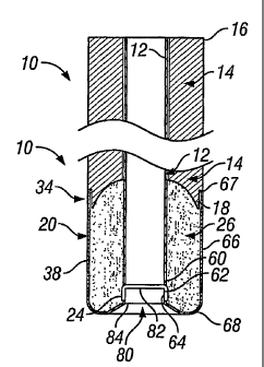
[00181 FIG. 1 illustrates an apparatus 10 for locating a puncture site in a
blood vessel wall
and for inhibiting blood loss from the puncture site according to the present
invention.
The apparatus 10 includes a tube 12, an elongated member 14, a dissolvable
distal capsule
20, and sponge 26 located inside the dissolvable distal capsule 20. The
elongated member
14 has a proximal end 16 and a distal end 18, and is positioned around the
tube 12. In a
preferred embodiment, the distal end 18 of the elongated member 14 has a
substantially
concave spherical shape. However, it can be appreciated that the distal end 18
of the
elongated member 14 can have any concave shape including a rectangular, a
stepped or a
flat surface which accommodates the sponge 26 located inside the dissolvable
distal
capsule 20. At the distal end 18 of the elongated member 14, the elongated
member 14
has a contact zone 34 in which the elongated member 14 has an outer diameter
which is
slightly smaller than the outer diameter of the more proximal portion of the
elongated
member 14 to allow the dissolvable distal capsule 20 to slide onto the contact
zone 34 of
the elongated member 14. In the preferred embodiment, the outer diameter of
the
elongated member 14 in the contact zone 34 is equal to the inner diameter of
the
dissolvable distal capsule 20, and the outer diameter of the distal capsule 20
is equal to
the outer diameter of the elongated member proximal to the contact zone 34 to
provide a
smooth transition from the dissolvable distal capsule 20 to the elongated
member 14. The
outer diameter of the elongated member 14 proximal to the contact zone 34 is
slightly
larger than the access sheath or device that occupied the vessel puncture, and
preferable 2
Fr larger.
CA 02503823 2005-04-26
WO 2004/041122 PCT/US2003/035385
[0019] The tube 12 has a proximal end 22 and a distal end 24 and extends
longitudinally
from the proximal end 16 beyond the distal end 18 of the elongated member 14.
The tube
12 has an inner diameter of about.040 to .120 inches, preferably about.050 to
.090 inches,
and should loosely accommodate a guidewire 30, as shown in FIG. 3. The tube 12
has a
wall thickness of about 0.0005 to 0.005 inches and preferably 0.001 to 0.002
inches. At
the distal end 24 of the tube 12, the inner diameter 62 of the tube 12 is
slightly greater than
the inner diameter 60 of the tube 12 along its proximal portion to accommodate
a
cylindrical section 80 of the dissolvable distal capsule 20. In a preferred
embodiment, the
inner diameter 60 of the tube 12 is equal to the inner diameter 64 of the edge
of the
dissolvable distal capsule 20. For reasons which will be appreciated by those
skilled in the
art, the tube 12 can optionally be coated or otherwise protected with a
material which
inhibits blood coagulation. By way of example and not of limitation, the tube
12 can be
coated with material including heparin (e.g. heparinized), tPa, or other
functionally similar
materials or compounds which inhibit or prevent blood from clotting or
otherwise
coagulating in the tube 12.
[0020] The dissolvable distal capsule 20 is positioned around the tube 12, and
has a
proximal end 67 and a distal end 68. The dissolvable distal capsule 20 and the
tube 12
form a coaxial space 66 therebetween for the sponge 26. The proximal end 67 of
the
dissolvable distal capsule 20 fits snugly around the distal end 18 of the
elongated member
14 and can be attached thereto by adhesive or gelatin solution, or by wetting
the capsule so
that it becomes sticky prior to positioning the capsule 20 around the tube so
that the
capsule and the tube are bonded to one another. Alternatively, the capsule 20
can be held
to the elongated member 14 by frictional engagement or by an interlock system
such as an
annular ring 76 formed in the capsule 20 and a corresponding annular groove 78
formed
in the elongated member 14, as shown in Fig. I a.
[0021] The dissolvable distal capsule 20 includes an outer tubular section
having a
proximal end 67 and a distal end 68. The proximal end 67 is open, having an
inner
diameter slightly greater than or equal to the outer diameter 36 of the
elongated member
14 at the elongated member's distal end 18. The distal end 68 of the
dissolvable distal
capsule 20 is rounded to prevent catching on subcutaneous tissue as the
apparatus 10 is
inserted through the epidermal outer layer and subcutaneous tissue. The distal
end of the
capsule 20 has cylindrical section 80 for receiving the tube 12. The
cylindrical section 80
6
CA 02503823 2010-10-29
WO 2004/041122 PCT/US2003/035385
has a proximal end 82 and a distal end 84, and the outer diameter of the
cylindrical section
80 is approximately equal to or slightly smaller than the inner diameter of
the tube 12.
[0022] The elongated member 14 is preferably a rigid or semi-rigid polymer
such as PVC
(polyvinyl chloride) or polycarbonate, but may be made of any suitable
material, including
SST. The tube 12 can be made from any number of polymers or from thin wall
SST. The
dissolvable distal capsule 20 is made from known absorbable, biocompatible
materials,
such as gelatin films like Gelfilm (R) from Upjohn or like gel-cap vitamins.
Preferably we
use gelatin film; preferably the hardness of the gelatin film forming the
distal capsule is
between about 40 and about 80 on the Shore A scale; and preferably it has a
bloom of at
least 270, which is normally called "high" bloom. However, in some
circumstances the
gelatin film could have a hardness and bloom outside these ranges.
[00231 The sponge 26 is preferably a liquid permeable, water soluble gelatin
based
sponge. Other hemostatic material can be used as well, instead of sponge 26,
such as
fibrillar collagen, collagen sponge, regenerated oxidized cellulose, gelatin
powder, or
hydrogel particles. Alternatively, the sponge may be composed of an absorbable
collagen ._
or other types of absorbable plolymers. One type of absorbable sponge material
which is
acceptable for use in the present invention is GelfoamTM, manufactured by the
Pharmacia
& Upjohn Company. GelfoamTM is a porous, pliable, cross-linked gelatin
material and is
available commercially in sheet form as pre-compressed or non-compressed
sponge.
Alternatively, the sponge can be made by mixing a suitable organic solvent
(e.g.,
formaldehyde) with an aqueous solution of gelatin. The organic solvent
facilitates the
cross linkage of gelatin polymers. It is expected that glutaraldehyde may also
be suitable.
The resulting solution is then incubated typically at slightly above room
temperature
(3 0 . degree.-40. degree. C.). Thereafter, the solutoin is aerated to cause
it to foam, and the
foam is dried to produce the absorbable sponge material.
100241 Suitable absorbable sponge materials are described in U.S. Pat. No.
2,465,357.
[00251 The apparatus 10 may be assembled by placing the tube 12 within the
dissolvable
distal capsule 20, then compressing the sponge 26 and placing it within the
coaxial space
66 between the tube 12 and dissolvable distal capsule 20. The sponge can be
compressed
to between 90% and 5 % of its uncompressed cross-sectional thickness. The
elongated
member 14 is then placed over the proximal end 22 of the tube 12 and inserted
into the
7
CA 02503823 2005-04-26
WO 2004/041122 PCT/US2003/035385
dissolvable distal capsule 20 and can be used to apply pressure to further
compress the
sponge, if desired.
[0026] FIG. 2 illustrates an alternative embodiment of apparatus 10 of FIG. 1
further
including a control tip assembly 40. The control tip assembly 40 at its
proximal end is
mounted to a tube 54. The control tip assembly 40 includes a proximal end
portion 42, a
distal end 46 portion having a distal port 50, and a central portion 44
between the proximal
end portion 42 and the distal end portion 46. The control tip assembly 40
includes a
lumen 51 which extends longitudinally between proximal end portion 42 and the
distal end
portion 46. The lumen also extends through tube 54. For reasons which will be
readily
appreciated by one of ordinary skill in the art, the lumen 51 can optionally
be coated or
otherwise provided with an interior surface which inhibits blood coagulation.
Further, by
way of example and not of limitation, the lumen 51 can be coated with material
including
heparin (e.g. heparinized), tPa, or other functionally similar materials or
compounds which
inhibit or prevent blood from clotting or otherwise coagulating in the lumen
51.
[0027] As illustrated in Figure 2, the center portion 44 preferably has a
constant outer
diameter. The proximal and distal ends are tapered; however, it can be
appreciated that
the proximal and distal end portions 42 and 46 can alternatively be a step,
rounded
shoulder, or the like. The control tip assembly 40 also includes a hole 52
which connects
the exterior of the control tip assembly'40 with the lumen 51. The lumen 51
has an inner
diameter selected to be larger than the external diameter of a guidewire,
preferably an
exchange wire, used therewith. Furthermore, a plurality of holes (not
illustrated) can be
formed in the control head, circumferentially spaced and at the same
longitudinal location
as hole 52.
[0028] The proximal and distal portions 42, 46 of the control tip assembly 40
can be
relatively thin walled such that the internal dimensions of the lumen 51 in
the central
portion 44 is larger than in the proximal end portion 42 and distal portion 46
of the control
tip assembly 40. As also described briefly above, the distal portion 46 of
control tip
assembly 40 includes a distal port 50 having an internal opening diameter also
selected to
be larger, and preferably only slightly larger, than the external diameter of
the guidewire
30 used with the control tip assembly. While the function of the distal port
50 in
conjunction with a guidewire 30 will be described in greater detail below, one
aspect of
the present invention is that by selecting the external diameter of guidewire
30 and the
inner diameter of the distal port 50 to be only slightly different, blood flow
into interior of
8
CA 02503823 2005-04-26
WO 2004/041122 PCT/US2003/035385
control tip assembly 40 is greatly restricted, thus allowing the hole 52 to be
the sole
entrance into the control tip for blood to flow up the lumen 51 to indicate
that the control
tip assembly 40 has been located in a blood vessel.
[0029] Preferably, the control tip assembly is formed of a flexible,
biocompatible material,
such as a thermoplastic. By way of example and not of limitation, the material
out of
which the control tip is formed has a Shore hardness between about 98A-74D.
[0030] For the control tip assembly herein, the outer diameter of the central
portion 44 is
between about 4 French and about 10 French, preferably between about 6 French
and
about 8 French. It is preferably equal to or similar in diameter to the access
sheath that
was used to make the puncture. The length of the control tip assembly, between
the distal
most end and the proximal end of the proximal end portion 42, should be at
least about 1
inch and preferably about 8 inches (6.4 cm), and more preferably about 2 to 4
inches.
Control tip assemblies of these dimensions are well suited for controlling
puncture sites as
described herein, particularly puncture sites used during percutaneous-type
vascular
access.
[0031] FIG. 3 illustrates the operation of the apparatus 10 as shown in FIG.
1. After an
endoluminal procedure which has been performed using, in part, a percutaneous
access
sheath for access to the patient's vasculature, a guidewire 30 is advanced
through the
sheath, into the patient's blood vessel 72 through a puncture site 70 in the
vessel wall, and
the sheath is removed. The apparatus 10 is then placed over the guide wire 30
and pushed
through the patient's skin. The operator uses the apparatus 10 to locate the
desired
delivery location by bumping into the artery 72. Once the desired delivery
position is
achieved, the operator retracts the tube 12 to expose at least part of the
sponge 26 to blood
from blood vessel 72, which starts the process of sponge expansion.
Simultaneously, the
dissolvable distal capsule 20 is exposed to blood and begins to soften and
dissolve. The
dissolvable distal capsule 20 dissolves in about 30 sec. to 10 min. and
preferably in about
1 minute. Once the dissolvable distal capsule has dissolved, the sponge 26 is
free to
expand into the puncture site. The dissolvable distal capsule 20 will also
release itself
from the elongated member body 14 as a result of softening and dissolving of
the capsule.
During and after dissoluton of the capsule the operator may apply pressure
over the site.
Then the operator can then apply diffuse external pressure to the tissue over
the sponge 26
and remove the guidewire 30 and the elongated member 14.
9
CA 02503823 2005-04-26
WO 2004/041122 PCT/US2003/035385
[0032] The use of the Fig. 2 embodiment of apparatus 10 is shown in FIG. 4.
The
operator places the control tip assembly 40 over the proximal end of the
guidewire 30
which extends from the patient's artery and pushes the apparatus through the
patient's
skin. The apparatus 10 locates the desired location by bumping into the
arterial puncture
site 70. The control tip assembly 40 provides additional benefits such as
hemostasis and
bleedback via the bleedback hole 52 or through the tube 54. Once in the
desired delivery
location, the tube 12 is retracted to expose the sponge 26 from the puncture
site 70 and the
blood vessel 72. This starts the process of sponge 26 expansion. When the user
observes
that the bleedback of the tube 54 is diminishing significantly, the control
tip assembly 40
can be retracted far enough to control the puncture site 70. As discussed
above in
connection with Fig. 3, the dissolvable distal capsule 20 softens and
dissolves, releasing
the sponge 26 into the puncture site and detaching the sponge 26 from the
elongated
member 14. The control tip assembly 40 is then completely removed from the
puncture
site 70 and the skin 74. During and after dissoluton of the capsule the
operator may apply
pressure over the site The operator then applies diffuse external pressure to
the tissue over
the sponge 26 and removes the guidewire, elongated member 14 and tube 12, if
it has not
already been removed.
[0033] In an alternative embodiment illustrated in FIG. 5, the tube 12 shown
in FIG. 1 is
eliminated. The apparatus 90 includes an elongated member 94 having a lumen 92
for
receiving a guidewire 110, a dissolvable distal capsule 100 positioned around
the lumen
92 and a sponge 116 located inside the dissolvable distal capsule 100. The
lumen 92
(which is defined by the inner surface of the elongated member 94) for
receiving the
guidewire 110 extends from a proximal end 96 of the elongated member 94 to a
distal end
98 of the elongated member 94. A dissolvable distal capsule 100 attaches to
the distal end
98 of the elongated member 94 as described above. In this embodiment the
dissolvable
capsule includes an inner cylindrical portion 102 that extends approximately
the same
length as the outer cylindrical portion 104 and into at least a portion of the
elongated
member 94. The capsule has a rounded end 106 extending between the inner
cylindrical
portion 102 and the outer cylindrical portion 104.
[0034] In operation, the apparatus 90 as shown in FIG. 5 is placed over the
proximal end
112 of a guidewire 110 extending from a patient's artery and the apparatus 90
is advanced
into the patient. The apparatus 90 locates the desired delivery location by
bumping into
the arterial puncture site to obtain the desired delivery position. This
starts the process of
CA 02503823 2005-04-26
WO 2004/041122 PCT/US2003/035385
sponge 116 expansion, wherein the dissolvable distal capsule 100 begins to
soften and
dissolve rapidly. Once the dissolvable distal capsule 100 has dissolved, the
sponge 116 is
free to expand into the puncture site and secure itself within the puncture
site. The
dissolvable distal capsule 100 will also release itself from the elongated
member 94 body
as a result of softening and dissolving of the dissolvable distal capsule 100.
[0035] Figure 6 illustrates another embodiment of the present invention. This
embodiment shows a hemostasis device 120 including a dissolvable capsule 122
substantially the same as the distal capsule 100 shown in Fig. 5, with the
exception that the
hemostasis device of this embodiment is not designed to be connected to an
elongated
member such as the elongated member 94 shown in Fig. 5. In the embodiment of
Fig. 6
the proximal end 124 of the capsule 122 can be open, or it can be closed as is
the rounded
end 106.
[0036] Figure 7 illustrates another embodiment similar to the embodiment in
Fig. 6.
However, in the Fig. 7 embodiment a retention tip 130 is affixed to the
rounded end 106.
The retention tip is substantially cylindrical and the central lumen of the
retention tip 130'
is coaxial with the lumen of the dissolvable capsule 122.
[0037] Figure 8 shows another embodiment, which is similar to the embodiment
in Fig. 7.
However, in the Fig. 8 embodiment a plurality of retention anchors 132 are
provided on
the capsule 122. The retention anchors 132 consist of one or more ridges
formed around
the circumference of the capsule 122, and their function will be described
below.
[0038] As shown in Fig. 8, the hemostasis device 120 is inserted into the
patient's skin 74.
During the insertion procedure the operator uses the retention tip 130 to help
maintain the
hemostasis device 120 at its proper location relative to the puncture site 70.
Also, the
retention anchors 132 help keep the device located in the proper position
while the
operator removes the wire 30 and thereafter until the device has dissolved.
The operator
may insert the hemostasis device so that it extends above the surface of the
patient's skin
140 or can push it below the surface of the patient's skin 142.
[0039] Fig. 9 shows another embodiment. In this embodiment a proximal
dissolvable
capsule 144 is affixed to the proximal end of a distal dissolvable capsule
145. Both
dissolvable capsules 144 and 145 contain compressed sponge which is not shown
for the
purpose of clarity. In this embodiment, the proximal dissolvable capsule 144
has a
diameter smaller than the diameter of the distal dissolvable capsule 145. A
lumen 146
extends through the device.
11
CA 02503823 2005-04-26
WO 2004/041122 PCT/US2003/035385
[0040] Fig. 10 shows a placement device 156 to aid in the insertion and
placement of a
hemostasis device shown in Fig. 9. The placement device includes a cylindrical
handle
150 and a cylindrical column 152 affixed to the distal end of the handle. A
lumen 154 is
located axially through the handle 150 and column 152.
[0041] Figs. 11 and 12 illustrate the operation of the devices of fig. 9 and
10. In this
embodiment the hemostasis device of Fig. 9 is inserted into the lumen of the
placement
device until the proximal part of the distal capsule 145 contacts the distal
end of the
column 152. Then the wire 30 is inserted through the lumen 146 of the device
of Fig. 9
and the operator uses the handle to push the hemostasis device through the
patient's skin
until the distal dissolvable capsule 145 contacts the outer surface of the
blood vessel 72.
Then the operator retracts the placement device 156, leaving the hemostasis
device in
place as shown in Fig. 12. The guide wire can be removed before or after
removal of the
placement device 156.
[0042] Fig. 13 illustrates another embodiment. This embodiment includes a
control tip
assembly 40 as shown in Fig. 2 and described above. A proximal gelatin capsule
158 is
connected to the control tip 40 assembly proximally thereof. The proximal
gelatin capsule
158 consists of a truncated cone-shaped portion 160 and a cylindrical portion
162
connected to the distal end of the cone-shaped portion, both of which are
constructed of
the same material as the dissolvable distal capsule 20, e.g. gelatin. Located
within the
proximal gelatin capsule 158 is a compressed sponge 164 which is formed of the
same
material as sponge 26. The proximal gelatin capsule 158 includes cylindrical
openings at
each end to fit snugly over the control tip 40 and snugly over the tube 54 so
when an
operator pushes the device through a patient's skin there is minimal
frictional resistance
between the leading edge of the proximal gelatin capsule 158 and the skin.
Furthermore,
the compressed sponge 164 can be packed tightly against the tube 54 and
control tip
assembly 40 to provide friction therebetween so that that proximal gelatin
capsule 158
remains in place when the operator pushes the device through the patient's
skin.
Alternatively, the control tip assembly 40 and proximal gelatin capsule 158
may be
inserted through a procedural access sheath which is already in place.
[0043] The embodiment shown in Fig. 14 is similar to the embodiment shown in
Fig. 13,
with the exception that the control tip assembly 40 is formed of rapidly
dissolvable
material such as the material of the dissolvable distal capsule 20, described
above with
reference to Fig. 1.
12
CA 02503823 2005-04-26
WO 2004/041122 PCT/US2003/035385
[0044] In operation of the embodiments of Figs 13 and 14, an operator inserts
the devices
through a patient's skin in the same manner as the embodiments described
above. When
bodily fluid contacts the proximal gelatin capsule the capsule dissolves
thereby releasing
the compressed sponge 164 which provides hemostasis.
[0045] Fig. 14a shows an embodiment where the distance from the distal end of
the
proximal gelatin capsule 158 to the hole 52 is located at one of three
alternative positions,
52a, 52b or 52c. Position 52a is chosen so that when the assembly 188 is
pushed in and
the operator is first able to observe bleed back due to blood from inside the
vessel 72
entering the hole 52, the device is properly positioned. In this example,
position 52a is
chosen so that the hole 52a is located a distance of dl from the distal end of
the proximal
gelatin capsule 158 so that the hemostatic material is released just outside
the vessel.
Alternatively, bleed back hole 52b is used, which is positioned at d2 where d2
is less than
dl such that the assembly 188 is pushed in until bleed back indication occurs
and then
withdrawn until bleed back indication first stops in which case the device is
properly
positioned. In this example d2 is chosen to position the hemostatic material
just outside
the vessel. Alternatively the bleed back hole 52c may be used, which is
positioned at d3
where d3 is less than d2 so that the assembly 188 is pushed in until bleed
back indication
occurs and then withdrawn until bleed back first stops and then withdrawn an
additional
predetermined distance. In the example shown d3 and the predetermined distance
are
chosen to position the hemostatic material just outside the vessel.
10046] For the embodiments shown in Figs 13, 14 and 14a the portion of the
tube 54
extending proximally of the proximal gelatin capsule 158 may have a diameter
smaller
than the control tip 40 or equal to the control tip 40. If the tube 54 is
smaller than the
control tip 40 and the control tip outside diameter is equal to or slightly
smaller than the
inside diameter of the access sheath 182, the capsule may be positioned as
shown in Fig
14b. Starting with the sheath already extending into a vessel 72, the assembly
188 is
pushed in through the sheath 182 until the cylindrical portion 162 extends
distally of the
distal end 190 of the sheath 182 and bleed back indication is observed via
blood entering
the distal end 190 of the sheath. The assembly 188 and sheath 182 are then
withdrawn as
one until bleed back indication first stops. The sheath 182 and assembly 188
are then
withdrawn an "additional distance" to properly position the hemostatic
material. In Fig.
14b the "additional distance" is equal to "T", the length of the proximal
capsule 158,
excluding the length of the cylindrical portion 162 thereof.
13
CA 02503823 2005-04-26
WO 2004/041122 PCT/US2003/035385
[0047] Fig. 15 illustrates a conventional biopsy device, including a needle
180 and a guide
182 which has a lumen 184 (show in Fig.) . After the operator collects a
tissue sample
with the needle 180 the needle is removed, leaving the guide 182 in place. As
shown in
Fig. 16 the operator then inserts a hemostasis device 186 through the guide
182. The
hemostasis device 186 can be formed by rolling a sheet of sponge material
tightly to form
a cylinder and coating the cylinder with gelatin. Optionally, before rolling
the sponge
material the operator can moisten the surface of the sponge with distilled
water so that the
surface dissolves slightly and the sponge sticks to itself and retains its
rolled configuration.
The operator can then coat the cylindrically formed sponge with a gelatin
solution,
preferably 5% plus or minus 0.5%, or the operator can insert the
cylindirically-fromed
sponge into a pre-formed gelatin capsule having the appropriate cylindrical
shape. The
operator can insert the hemostasis device 186 so that it extends beyond the
distal end of
the guide 182 so that the hemostasis device 186 contacts the patient's blood
and dissolves
to create hemostasis. The operator can remove the guide 182 partially or
completely at the
appropriate time as the hemostasis device 186 is dissolving.
[0048] Figure 17 illustrates another embodiment wherein the operator of the
biopsy device
completely removes the guide 182 without inserting the hemostasis device 186.
The
operator then inserts the hemostasis device into the patient's skin 74. If the
hemostasis
device is sufficiently long so that when it is completely inserted, a portion
remains above
the skin surface, the portion remaining above the skin surface can be trimmed
off flush
with or below the skin surface. Alternatively, as shown in Fig. 18 the
hemostasis device
can be shorter than the depth of the wound in the patient's skin, in which
case the operator
can push the homeostasis device 186 below the surface of the patient's skin
with an
appropriate tool such as a rod.
[0049] While the invention has been described in detail with reference to
preferred
embodiments thereof, it will be apparent to one skilled in the art that
various changes can
be made, and equivalents employed, without departing from the scope of the
invention.
All of the aforementioned documents are incorporated by reference in each of
their
entireties herein.
14