Note: Descriptions are shown in the official language in which they were submitted.
CA 02503858 2005-04-27
WO 2004/045441 PCT/US2003/033791
ELECTROSURGICAL GENERATOR AND METHOD WITH REMOVABLE
FRONT PANEL HAVING REPLACEABLE ELECTRICAL CONNECTION
SOCKETS AND ILLUMINATED RECEPTACLES
Field of the Invention
The invention generally relates to electrosurgery, and more specifically,
to a new and improved electrosurgical generator and method that uses
removable electrical connection sockets which accept plugs for electrosurgical
instruments and accessories and a removable front control panel which enables
more convenient access to the connection sockets and other electrical
equipment adjacent to the front panel for service when needed, among other
things.
Background of the Invention
Electrosurgery involves applying relatively high voltage, radio frequency
(RF) electrical power to tissue of a patient undergoing surgery, for the
purpose
of cutting the tissue, coagulating or stopping blood or fluid flow from the
tissue,
or cutting or coagulating the tissue simultaneously. The high voltage, RF
electrical power is created by an electrosurgical generator, and the
electrical
power from the generator is applied to the tissue from an instrument or
handpiece manipulated by a surgeon during the surgical procedure.
In monopolar electrosurgery, the handpiece includes a single active
electrode. The active electrode is applied to the tissue, and the electrical
energy travels from the generator, through a conductor to the handpiece, from
the active electrode of the handpiece into the tissue of the patient, where
the
cutting, coagulating or simultaneous cutting and coagulating effect is
achieved
at the interface of the active electrode with the tissue. The electrical
current is
distributed into the patient, collected from the patient by a return electrode
connected to the patient at a location remote from the surgical site, and is
returned to the electrosurgical generator by an electrical conductor connected
to the return electrode.
In bipolar electrosurgery, the handpiece generally takes the form of a
forceps. The active electrode and the return electrode are attached at
opposite
CA 02503858 2005-04-27
WO 2004/045441 PCT/US2003/033791
ends of the arms of the forceps. Tissue is grasped between the active and
return electrodes and the electrosurgical energy is transferred directly
between
the active and return electrodes through the tissue. Bipolar electrosurgery is
generally used only for coagulating tissue, such as by squeezing a severed
vessel and applying the electrosurgical energy to seal the end of the severed
vessel.
The surgeon controls the power delivered to the handpiece by
depressing a finger switch on the handpiece, or by stepping on a foot switch
which is associated with the particular handpiece. Depressing a finger switch
or
stepping on a foot switch delivers an activation signal to the electrosurgical
generator. The electrosurgical generator responds to the activation signal by
delivering the high power electrosurgical energy to the handpiece with which
the
activation signal is associated.
Frequently during the surgical procedure, a surgeon will use different
handpieces on an alternating, interchangeable basis. For example, the
surgeon may use one monopolar handpiece for cutting, another monopolar
handpiece with a different shaped active electrode for coagulating, and
bipolar
forceps for coagulating blood flow from severed vessels. In some complex
surgical procedures, two or more surgeons may operate on the same patient at
the same time at different surgical sites, using the same electrosurgical
generator. To accommodate these situations, it is typical that the multiple
handpieces are simultaneously connected to a single electrosurgical generator.
The electrosurgical generator typically includes a front control panel that
has sockets into which prongs of electrical connector plugs of the handpieces
are inserted, thereby connecting the handpieces to the electrosurgical
generator. The front control panel also typically includes an electrical
socket by
which to connect a connection plug of the return electrode. In addition, the
front control panel also usually provides a connector by which to connect a
connection plug for the foot switch.
Over the normal course of using the electrosurgical generator, the
connection plugs of the handpieces, return electrode and foot switch are
inserted into and removed from the electrical connection sockets generator
many times. At least one handpiece and one return electrode will be connected
2
CA 02503858 2005-04-27
WO 2004/045441 PCT/US2003/033791
for each surgical operation, and it is not unusual that a surgeon may replace
one or more of the handpieces or the return electrode during the course of a
procedure, particularly a relatively lengthy procedure. Thus, over the
lifetime of
the electrosurgical generator, thousands of physical connections of the
handpieces, return electrodes and foot switches will be made to the
electrosurgical generator. Such usage results in considerable wear on the
connection sockets of the electrosurgical generator. Typically, the handpieces
and return electrodes are disposable, so the wear on their connection plugs is
inconsequential. Because the usable lifetime of the functional components of
the electrosurgical generator is greater than the typical usable lifetime of
the
electrical connection sockets in the front panel, it is typical that the front
panel
electrical connection sockets must be replaced periodically during the course
of
normal maintenance of and service on the electrosurgical generator.
Other electronic components of the electrosurgical generator are also
subject to wear and periodic replacement. For example, it is typical to switch
the high voltage RF electrosurgical power to the handpieces through output
relays. The output relays are typically located behind the front panel within
an
enclosure or housing of the electrosurgical generator. Locating the output
relays behind the front panel minimizes the possibility that the high voltage
RF
electrosurgical power will create unwanted electrical noise and other unwanted
signal anomalies in the other relatively low voltage components of the
electrosurgical generator, because the other relatively low voltage components
of the electrosurgical generator are usually positioned within the housing at
locations more remote from the front panel. The high voltage output relay
operates each time the surgeon depresses an activation control button on one
of the handpieces or steps on the foot switch. During the course of a single
electrosurgical procedure, activations of the high voltage output relay may
occur
hundreds of times. The high voltage output relays may be operated tens or
hundreds of thousands of times during the course of normal use of a typical
electrosurgical generator. Such a large number of activations cause the high
voltage output relay to become worn and potentially unreliable, thereby
requiring the output relays to be replaced on a regular maintenance schedule.
3
CA 02503858 2005-04-27
WO 2004/045441 PCT/US2003/033791
In addition to periodically servicing the electrical connection sockets in
the front panel and replacing the high voltage output relays located behind
the
front panel, there are many other reasons for providing convenient access to
the electrical and electronic components of the electrosurgical generator
located within the housing behind the front panel.
Adequate visibility of the front panel plug-receiving receptacles is difficult
or impossible under the circumstances where the electrosurgical generator is
used in a substantially darkened operating room. Minimally invasive surgery is
performed in an almost completely darkened operating room. The surgical
procedure progressing within the patient is pictured by a miniature camera
inserted into the patient, and the surgeon and the surgical personnel observe
the procedure on television-like display monitor located next to the patient
in the
operating room. Darkening the operating room enhances visualizing the
procedure on the display monitor. In other circumstances, it is unusual for
the
operating room to be darkened so that intense illumination can be directed
only
on the surgical site. Illuminating the surgical site in this manner enhances
the
ability of the surgeon to observe the tissue and the progress of the surgical
procedure. Under both of these circumstances involving darkening of the
operating room, the control and operational features of the electrosurgical
generator will be less visible. If it is necessary to replace the handpieces
or the
return electrode during the course of a surgical procedure in a darkened
operating room, which is not unusual in relatively lengthy or complicated
procedures, doing so is made difficult by the inability to clearly discern the
receptacles for the connector plugs and the other operational and control
features of the electrosurgical generator.
Summary of the Invention
The improvements of this invention allow for convenient and relatively
rapid replacement and maintenance of worn electrical connection sockets on
the front panel and replacement and maintenance of high voltage relays
located behind the front panel in an electrosurgical generator, as well as
relatively convenient and quick access to other internal components of the
electrosurgical generator which are either connected to the front panel or
located behind the front panel. In addition, the improvements of the present
4
CA 02503858 2005-04-27
WO 2004/045441 PCT/US2003/033791
invention include illuminating the plug-receiving receptacles and other
receptacles and control features located on the front panel to facilitate
making
quick and effective connections and disconnections as well as taking other
electrosurgical generator control actions in a darkened environment, while
reducing the possibility of the closely-adjacent high voltage RF
electrosurgical
output power inducing unwanted noise and signal anomalies in other functional
components of the electrosurgical generator or the camera and monitoring
devices used in minimally invasive surgery.
One aspect of the invention relates to improvements in accessing
internal components within an electrosurgical generator. Access is achieved by
removing the front panel from the housing, and as part of the act of removing
the front panel from the housing, separating an electrical connection between
an electrical connector member and the circuit board. The components
attached to the front panel and within the electrosurgical generator adjacent
to
the front panel are easily accessed by removing the front panel.
Another aspect of the invention relates to an improved plug-receiving
receptacle which permits the replacement of a socket-defining electrical
connector member. An insert receptacle is attached to a housing panel, and a
retainer is located at the rear end of the insert receptacle. The retainer
contacts the connector member at the rear end of the insert receptacle to
retain
the connector member within the insert receptacle. Removing the retainer
releases the connector member so that it can be replaced in the insert
receptacle.
Another aspect of the invention relates to an improved mechanical and
electrical connection between an electrical connector member of the plug-
receiving receptacle or other component attached to the housing panel of the
electrosurgical generator. A resilient electrical contact is connected to the
circuit board within the housing at a position to contact an extension portion
of
the connector member. The resilient electrical contact provides bias force to
establish an electrical and mechanical connection between the connector
member and the other internal components of the electrosurgical generator.
The bias force facilitates a good electrical connection and convenient
separation.
5
CA 02503858 2009-12-04
Another aspect of the invention relates to illuminating the plug-receiving
or other receptacle of the electrosurgical generator. A light emitter is
connected
to project light into the plug-receiving receptacle. An optical fiber is
connected to
the light emitter to conduct light to the light emitter. The non-electrical
light
emitter and optical fiber will not pick up electrical noise and anomalous
signals
generated by the high voltage RF electrosurgical power conducted through the
plug-receiving receptacle. The functionality of the electrosurgical generator
becomes less susceptible to noise and anomalous functionality created by such
noise.
Another aspect of the invention provides an electrosurgical generator
which generates high-frequency, high-voltage electrosurgical electrical power,
comprising: a plug-receiving receptacle at an exterior panel of a housing of
the
electrosurgical generator at which to transfer the electrosurgical power from
the electrosurgical generator to an accessory, the plug-receiving receptacle
including a socket for receiving a prong of a connector plug connected to the
accessory; an electrically-energized source of light located within the
housing
at a position remote from the plug-receiving receptacle; an optical conductor
extending from the light source for conducting the visible light from the
light
source to the plug-receiving receptacle; low-voltage electrical components
located within the housing; characterized by: the light source producing
visible
light. The electrosurgical generator can further comprise a light emitter
positioned at the plug-receiving receptacle to project the visible light from
the
optical conductor onto the plug-receiving receptacle. The optical conductor
can further comprise an optical fiber.
The plug-receiving receptacle can further comprise: an insert
receptacle connected to the exterior panel and having a front end connected to
the plug-receiving receptacle and extending rearwardly from the plug-
receiving receptacle to a rear end, the front end of the insert receptacle
defining a front opening to the plug-receiving receptacle; a connector member
which defines the socket, the socket extending from a front end of the
connector member toward a rear end of the connector member, the connector
member removably positioned within the insert receptacle with the front end
of the connector member positioned adjacent to and within the front opening
of the insert receptacle with the socket accessible through the front opening;
and a retainer
6
CA 02503858 2009-12-04
located at the rear end of the insert receptacle and contacting the connector
member at the rear end of the insert receptacle to retain the connector member
within the insert receptacle. The insert receptacle can further include a
shoulder surrounding the front opening at the front end of the insert
receptacle;
and the shoulder of the insert receptacle can contact the front end of the
connector member to retain the connector within the insert receptacle. The
connector member can be insertable into and removable from the insert
receptacle at the rear end of the insert receptacle, upon removal of the
retainer.
The connector member can further include a shoulder located adjacent to the
rear end of the insert receptacle; and the retainer can further contact the
shoulder of the connector member. The connector member can be confined
within the insert receptacle by contact of the front end of the connector
member with the shoulder of the insert receptacle and by contact of the
shoulder of the connector member with the retainer at the rear end of the
insert
receptacle. The retainer can include a retaining panel which can have a hole
formed therethrough, the connector member can include a shank portion
extending beyond the rear end of the insert receptacle, and the retaining
panel
can be connected at the rear end of the insert receptacle with the hole
surrounding the shank portion.
The electrosurgical generator can further comprise: a circuit board
located behind the exterior panel; and an electrical contact connected to the
circuit board at a position to contact the shank portion of the connector
member to establish an electrical connection between the circuit board and the
connector member.
The connector member can include an extension portion extending
rearwardly beyond the rear end of the insert receptacle; and can further
comprise: a circuit board located behind the exterior panel, and an electrical
contact connected to the circuit board at a position to contact the extension
portion of the connector member to establish an electrical connection between
the circuit board and the connector member. The electrical contact can
comprise a resilient member. The resilient member can comprise a leaf spring
contact which can be deformed upon physical contact with the extension
portion. The exterior panel can be connectable to and disconnectable from the
housing; and the extension portion can separate from the resilient member
upon disconnection of the exterior panel from the housing. The resilient
member can resiliently deflect to mechanically and electrically contact the
6a
CA 02503858 2009-12-04
extension portion upon connection of the exterior panel to the housing and can
mechanically separate from the extension member upon disconnection of the
exterior panel from the housing. The connector member can include a forward
portion which can define the socket and the front end, the forward portion can
be located substantially within the insert receptacle, the extension portion
can
extend rearwardly from the forward portion, and the extension portion can be
of smaller cross-sectional size than the forward portion; and the retainer can
be
connected at the rear end of the insert receptacle and can contact the
extension
portion which can tend to confine the connector member relative to the insert
receptacle by contact of the front end of the connector member with the
shoulder of the insert receptacle and by contact of the extension portion with
the retainer at the rear end of the insert receptacle.
The retainer can include a bracket which can extend forwardly from
the rear end of the insert receptacle to the front end of the insert
receptacle;
and the light emitter can connect to a front end of the bracket to project the
light onto the plug-receiving receptacle. The light emitter can be connected
to
the front end of the bracket by a retaining portion of the bracket; and the
light
emitter can be removable from the retaining portion of the bracket.
Another aspect of the invention provides a method of projecting light
onto a plug-receiving receptacle at an exterior panel of a housing of an
electrosurgical generator which generates high-frequency, high-voltage
electrosurgical electrical power, comprising: transferring the electrosurgical
power from a socket of the plug-receiving receptacle to a prong of a connector
plug received within the socket in the plug-receiving receptacle, the plug
conducting the electrosurgical power to an accessory connected to the plug;
electrically energizing a source of light within the electrosurgical generator
at
a position remote from the plug-receiving receptacle; projecting light from
the
light source through a non-electrically conductive optical conductor onto the
plug-receiving receptacle; characterized by: the light source emitting visible
light. The method can further comprise projecting the visible light from the
optical conductor onto the plug receiving receptacle with a light emitter. The
method can further comprise conducting the visible light from the light source
to the plug-receiving receptacle through an optical fiber. The method can
further comprise: using a connector member to define the plug-receiving
receptacle; positioning the connector member in an insert receptacle which has
a front end attached to the exterior panel at a front opening and a rear end
6b
CA 02503858 2009-12-04
extending from the exterior panel into the housing; and retaining the
connector
member within the insert receptacle at both the front and rear ends of the
insert
receptacle. The method can further comprise: including a circuit board within
the electrosurgical generator behind the exterior panel; extending an
extension
portion of the connector member rearwardly beyond the rear end of the insert
receptacle; and resiliently contacting the extension portion of the connector
member with the circuit board to establish an electrical connection between
circuit board and the connector member. The method can further comprise:
removing the exterior panel from the housing; and separating the resilient
contact between the extension portion and the circuit board as a part of the
act
of removing the exterior panel from the housing. The method can further
comprise: removing the connector member from the insert receptacle after
removing the exterior panel from the housing; and inserting a different
connector member in the insert receptacle while the exterior panel is removed
from the housing. The method can further comprise applying spring bias force
between the extension portion and the circuit board to establish and maintain
the electrical connection between the circuit board and the connector member.
The method can further comprise removing the spring bias force between the
extension portion and the circuit board when removing the exterior panel from
the housing.
A more complete appreciation of these and other aspects of the
invention and its scope, and the manner in which the present invention
achieves the above noted and other improvements, can be obtained by
reference to the appended claims and the following detailed description of a
presently preferred embodiment taken in connection with the accompanying
drawings which are briefly summarized below.
Brief Description of the Drawing
Fig. 1 is an external perspective view of an electrosurgical generator,
and a typical finger-switched actuated monopolar electrosurgical handpiece, a
typical foot-switched monopolar electrosurgical handpiece, a typical bipolar
electrosurgical handpiece, a typical foot switch, and a typical return
electrode,
all of which may be connected to the electrosurgical generator.
Fig. 2 is an enlarged cross-sectional view of a front panel of an
electrosurgical generator and some of the internal components of the
6c
CA 02503858 2009-12-04
electrosurgical generator shown in Fig. 1, taken substantially in the plane in
of
line 2-2 of Fig. 1.
Fig. 3 is an enlarged view of a portion of Fig. 2 illustrating details of
an electrical connection socket and details of its electrical connection to a
front
portion of an electronic circuit board within the electrosurgical generator.
Fig. 4 is a partial rear perspective view of an assembled relationship of
the front panel and a front portion the electronic circuit board of the
electrosurgical generator shown in Figs. 1-3, with an outer cover of the
enclosure of the electrosurgical generator removed for clarity.
6d
CA 02503858 2005-04-27
WO 2004/045441 PCT/US2003/033791
Fig. 5 is an exploded rear perspective view of the front panel and the
front portion of the electronic circuit board shown in Fig. 4.
Fig. 6 is an exploded rear perspective view of the front panel and
components of the electrical connection socket retained by the front panel
shown in Figs. 2 and 3.
Detailed Description
An electrosurgical generator 20, shown in Fig. 1, includes a front panel
22 at which to connect various conventional electrosurgical instruments and
accessories, including a finger-switched monopolar handpiece 24, a bipolar
handpiece or forceps 26, a foot-switched monopolar handpiece 28, and a return
electrode 30. The front panel 22 also includes various touch input switch
devices 32, displays 34 and indicators 36, which are used to control the
operation of the electrosurgical generator by setting cut, coagulation or
simultaneous cut and coagulation modes of electrosurgical operation and the
amount of electrosurgical power to be delivered in the selected mode of
operation, among other typical things. The front panel 22 functions as a user
interface for the electrosurgical generator 20 with regard to performing
input/output tasks. A typical foot switch 38 is also connected to the
electrosurgical generator 20, at a back or rear housing panel (not visible in
Fig.
1).
The front panel 22 locates and positions various electrical connector
plug- receiving receptacles 40, 42, 44 and 46 by which to electrically connect
the finger-switched monopolar handpiece 24, the bipolar forceps 26, the foot-
switched monopolar handpiece 28 and the return electrode 30, respectively.
The front panel 22 also includes another electrical connector plug-receiving
receptacle 48 by which to connect an additional finger-switched monopolar
handpiece (not shown) similar to the one handpiece 24 shown. The finger-
switched monopolar handpiece 24, the bipolar forceps 26, the foot-switched
monopolar handpiece 28 and the return electrode 30 each include an electrical
connector plug 50, 52, 54 and 56 which is inserted into the plug-receiving
receptacles 40, 42, 44 and 46 when connecting the finger-switched monopolar
handpiece 24, the bipolar forceps 26, the foot-switched monopolar handpiece
28 and the return electrode 30 to the electrosurgical generator 20,
respectively.
7
CA 02503858 2005-04-27
WO 2004/045441 PCT/US2003/033791
The connector plugs 50, 52, 54 and 56 are electrically connected by conductors
58, 60, 62 and 64 to the finger-switched monopolar handpiece 24, the bipolar
forceps 26, the foot-switched monopolar handpiece 28 and the return electrode
30, respectively.
The typical finger-switched monopolar handpiece 24 includes a finger
activation switch 66 for the surgeon to depress to activate the
electrosurgical
generator 20 to deliver electrosurgical power from the plug-receiving
receptacle
40 (or 48), to the connector plug 50, through the conductors 58 to the
handpiece 24, and from an active electrode 68 connected at the distal end of
the handpiece 24. One prong 70 of the connector plug 50 conducts the high
voltage RF electrosurgical power through one of the conductors 58 to the
active
electrode 68. Two other prongs 72 and 74 of the connector plug 50 conduct
activation signals from the activation switch 66 through the conductors 58 to
the
electrosurgical generator 20. The prong 72 conducts an activation signal from
the finger switch 66 indicating that coagulation mode power is to be delivered
to
the active electrode 68, and the prong 74 conducts an activation signal from
the
finger switch 66 indicating that cut mode power is to be delivered to the
active
electrode 68.
The foot-switched monopolar handpiece 28 is similar to the finger-
switched monopolar handpiece 24, except that the foot-switched monopolar
handpiece 28 does not include a finger switch 66 to activate the
electrosurgical
generator 20. Instead, the foot-switched monopolar handpiece 28 requires the
use of the foot switch 38 to activate the electrosurgical generator 20. The
foot
switch 38 includes a pedal 76 which is depressed by the foot of the surgeon,
and in response, the foot switch 38 delivers an activation signal through
conductors 77 to a prong 78 of a foot switch connector plug 79. In response to
the activation signal from the foot switch 38, the electrosurgical generator
20 is
activated and delivers electrosurgical power through the plug-receiving
receptacle 44 into which is the electrical connector plug 54 of the foot-
switched
monopolar handpiece 28 is connected.
The electrical circuit for monopolar current flow from the active electrode
68 through the patient is established by connecting the return electrode 30 to
the skin of the patient at a location remote from the surgical site. The
electrical
8
CA 02503858 2005-04-27
WO 2004/045441 PCT/US2003/033791
current is collected from the patient's body by the return electrode 30,
conducted through the conductors 64 and returned to the electrosurgical
generator through connector plug 56 which is inserted into the plug-receiving
receptacle 46. The plug receiving receptacle 46 for connecting the return
electrode 30 includes a pair of male prongs 80 which extend into female
sockets (not shown) of the connector plug 56.
Electrical energy for bipolar electrosurgery performed with the bipolar
forceps 26 is delivered from the plug-receiving receptacle 42 and conducted
through prongs 82 and 84 of the connector plug 52. The electrosurgical energy
is conducted from the plug-receiving receptacle 42 and into the prongs 82 and
84 of the connector plug 52, through the conductors 60 and delivered to
electrodes 86 and 88 connected at the distal ends of arms 90 and 92 of the
forceps 26. One of the electrodes 86 or 88 transfers current into the tissue
confined between the two electrodes 86 and 88 by squeezing the arms 90 and
92 and the other electrode 86 or 88 collects and returns the current from the
tissue. In bipolar electrosurgery, the electrosurgical current flows directly
between the electrodes 86 and 88, making the use of the return electrode 30
unnecessary. The electrosurgical generator is typically activated to deliver
the
bipolar electrosurgical energy to the forceps 26 by depressing the pedal 76 of
the foot switch 38, in the same manner as has been as has been described for
activating the foot-switched monopolar handpiece 28. Some types of bipolar
forceps 26 include a switch which generates an activation signal upon
squeezing the arms 90 and 92 together.
Each time the electrosurgical generator 20 is set up for use in monopolar
electrosurgery, the return electrode connector plug 56 and at least one
monopolar handpiece connector plug 50 and/or 54 must be connected into the
plug-receiving receptacles 40 (or 48) and/or 44, respectively. In addition, if
a
foot-switched monopolar handpiece 28 is connected, the foot switch connector
plug 79 must be connected into a receptacle located on the back panel (not
shown) of the electrosurgical generator 20. Each time the electrosurgical
generator is set up for use in bipolar electrosurgery, the bipolar handpiece
connector plug 52 must be inserted into the plug-receiving receptacle 42, and
the foot switch connector plug 79 of the foot switch 38 must be inserted into
the
9
CA 02503858 2009-12-04
foot switch receptacle (not shown) on the back panel of the electrosurgical
generator unless the bipolar forceps 26 are the type which have a switch which
activates upon squeezing the arms 90 and 92. After the surgical procedure is
completed, or when it is necessary to replace one of the handpieces 24, 26 or
28 or the return electrode 30 during the procedure, the connector plugs must
be removed from the plug-receiving receptacles to disconnect the handpieces
and other instruments from the electrosurgical generator. Over a normal
course of use of the electrosurgical generator 20, these connections will be
made and broken many times, perhaps thousands or tens of thousands of
times.
The repeated insertion and removal of the connector plugs into and
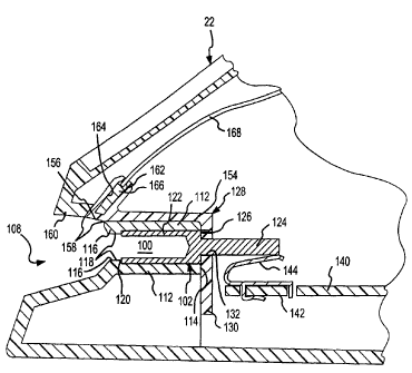
from the plug-receiving receptacles creates significant wear on a socket 100
of
a socket-defining connector member 102 which accepts and receives a prong
104 of a connector plug 106, as shown in Fig. 2. Each plug-receiving
receptacle 40, 42 and 48 (Fig. 1) includes at least one connector member 102
which defines and provides the socket 100 for each of the prongs 70, 72, 74,
82 and 84 of the connector plugs 50 and 52 which are connected within the
corresponding plug-receiving receptacle 40 (48) and 42 (Fig. 1), respectively.
Although only a single prong 104 of a single connector plug 106 is illustrated
in Fig. 2, the single prong 104 and connector plug 106 are representative of
the
prongs 70, 72, 74, 82 and 84 and connectors 50 and 52 illustrated in Fig. 1.
In
addition, Figs. 2 and 3 illustrate a single plug-receiving receptacle 108,
which
represents the plug receiving receptacles 40, 42 and 48 illustrated in Fig. 1.
The foot switch plug-receiving receptacle 44 (Fig. 1) does not typically
include a socket 100 or a socket-defining member 102 (Fig. 2), as is described
more completely in the U.S. patent application no. 2004/0097 1 1 7, filed 18
November 2002, for Monopolar Electrosurgical Multi-Plug Connector Device
and Method Which Accepts Multiple Different Connector Plugs.
With reference to Fig. 2, after the socket 100 has been worn to such an
extent that its dimensions are so large that an inadequate electrical
connection
may occur between the socket-defining member 102 and the prong 104, it is
necessary to replace the socket-defining member 102 with one that has an
appropriately sized socket 100 to establish a proper electrical connection
with
the prong 104 of the connector plug 106. To facilitate replacing worn socket-
CA 02503858 2009-12-04
defining members 102 with enlarged sockets 100, the front panel 22 (Fig. 1) is
made removable from an enclosure or housing 110 of the electrosurgical
generator 20 (Fig. 1), as is generally shown in Figs. 5 and 6. In addition,
connector members 102 which define the sockets 100 are made removable from
the front panel 22 and the plug-receiving receptacles (40, 42 and 48, Fig. 1),
as
shown in Fig. 6, to facilitate their replacement. Moreover, the socket-
defining
connector members 102 are easily disconnected from the internal electrical
components of the electrosurgical generator when the front panel 22 is removed
from the housing 110, as shown in Fig. 5. As a result, the socket defining
connection members 102 are easily replaceable and serviceable, as are other
components attached to the front panel 22.
As shown in Figs. 2 and 3, the front panel 22 includes insert receptacles
112 which are molded or formed in the front panel 22 and which project
rearwardly from the plug receptacle 108 into the interior of the
electrosurgical
generator. Each insert receptacle 112 is essentially a hollow tube-like
structure,
and one socket-defining connector member 102 is retained within each insert
receptacle 112. Each socket-defining connector member 102 is inserted into the
insert receptacle 112 from a rear open end 114 (Figs. 3 and 6) of the insert
receptacle 112. As best shown in Fig. 3, a shoulder 116 is formed surrounding
an
opening 118 at the front end of each insert receptacle 112. The shoulder 116
contacts a forward edge 120 of the socket-defining connector member 102 to
prevent the connector member 102 from moving forward out of the insert
receptacle 112. The opening 118 provides access into the socket 100 of the
connector member 102. As understood from Fig. 2, the prong 104 of the
connector plug 106 is inserted through the opening 118 and into the socket
100.
Each socket-defining connector member 102 has a front cylindrical
portion 122 within which the socket 100 is formed. The socket 100 is also
preferably formed in a cylindrical configuration, and extends from the forward
edge 120 rearwardly to a depth or distance which is approximately equal to or
slightly greater in length as the typical length of the each prong 104 of the
typical
plug connector 106 (Fig. 2). A rear extension or shank portion 124 extends
rearwardly from the rear of the front cylindrical portion 122. The shank
portion
11
CA 02503858 2005-04-27
WO 2004/045441 PCT/US2003/033791
124 also has a cylindrical outer configuration, but is of smaller diameter
than
the larger front cylindrical portion 122. A shoulder 126 transitions between
the
larger diameter front cylindrical portion 122 and the smaller diameter rear
shank
portion 124. The shoulder 126 is located slightly rearwardly of the
rearwardmost position of the socket 100. With the forward edge 120 of the
socket-defining connector member 102 abutted against the shoulder 116, the
shoulder 126 of the connector member 102 is approximately at the location of
the rear open end 114 of the insert receptacle 112.
The entire socket-defining connector member 102 is preferably formed
of good electrically conducting metallic material, such as brass, which is
capable of providing a good electrical and frictional connection between the
prong 104 and the socket 100. Because materials which offers the capability of
a good frictional fit and electrical contact, such as brass, are somewhat
soft, the
socket 100 is susceptible to wear as a result of the repeated insertion and
withdrawal of the prong 104. The susceptibility of the socket 100 to wear
makes it necessary to periodically replace the socket-defining connecting
member 102, usually during routine periodic maintenance of the electrosurgical
generator.
Each socket-defining connector member 102 is held in its insert
receptacle 112 by a retainer 128. Each retainer 128 includes a back retaining
panel 130 with a hole 132 through which the shank portion 124 of the connector
member 102 extends. The retaining panel 130 is connected to the front panel
22 by screws or other fasteners 134 (Fig. 6). Connected in this manner, the
retaining panel 130 of the retainer 128 contacts the shoulder 126 of the
socket-
defining connector member 102 to retain and trap the connector member 102
within the insert receptacle 112. The connector member 102 is held within the
insert receptacle 112 because the front end 114 contacts the shoulder 116 at
the front end of the connector member 102 and the shoulder 126 contacts the
retaining panel 130 of the retainer 128.. Although only a single hole 132 in
the
retaining panel 130 is illustrated in Figs. 2 and 3, each retaining panel 130
includes multiple holes 132 to accommodate the shank portions 124 of the
multiple socket-defining connector members 102 in each of the plug receiving
receptacles 40, 42 and 48 (Fig. 1) as is illustrated in Figs. 4-6.
12
CA 02503858 2005-04-27
WO 2004/045441 PCT/US2003/033791
he connection of each socket-defining connector member 102 to the
front panel 22 in the manner described causes the rear shank portion 124 to
extend rearwardly from the retaining panel 130. The rearwardly extending
shank portion 124 electrically connects the socket-defining connector member
102 to an electrical circuit board 140 which is mounted within the enclosure
110
of the electrosurgical generator. The electrical circuit board 140 is retained
within the housing 110 in such a way that its forward edge 142 is located
adjacent to the front panel 22 when the front panel 22 is connected to the
housing 110, as shown in Figs. 2-4. A resilient or leaf spring contact 144 is
connected at the forward edge 142 of the circuit board 140 at a position which
contacts the rearwardly extending shank portion 124 of each socket-defining
connector member 102, when the front panel 22 is connected to the housing
110. One leaf spring contact 144 electrically connects each of the socket-
defining connector members 102 to the circuit board 140.
The leaf spring contact 144 makes mechanical and electrical contact
with the shank portion 124 of the connector member 102 as shown in Fig. 3.
Upon contact, the shank portion 124 deflects the leaf spring contact 144
downwardly (as shown) to bias the leaf spring contact 144 against the shank
portion 124. The spring bias force keeps the leaf spring contact 144 firmly
engaged with the shank portion 124 to maintain a good electrical contact. An
electrically conductive path is thus established from the socket-defining
connector member 102 through the leaf spring contact 144 to the circuit board
140.
The leaf spring contacts 144 are electrically connected to conventional
circuit conductors (not shown) formed on the circuit board 140. The circuit
board electrical conductors conduct electrical signals between the various
components of the circuit board 140 and the leaf spring contacts 144. For
example, high voltage output relays 146 (Figs. 4 and 5) are connected to the
circuit board 140 to deliver electrosurgical power through the leaf spring
contacts 144 to the socket-defining connector members 102 for conduction to
the handpieces 24 and 28 (Fig. 1). Signals from the activation switch 66 of
the
finger-switched monopolar handpiece 24 are also conducted through socket-
defining connector members 102 to the circuit board 140, as a result of the
13
CA 02503858 2009-12-04
electrical connection of the connector members 102 through the leaf spring
contacts 144.
A foot-switched monopolar handpiece multi-plug connector device 150 is
connected to the front panel 22 as shown in Figs. 4-6. The foot-switched
monopolar multi-plug connector device 150 includes a rearwardly extending
electrical extension portion or contact member 152. The electrical contact
member 152 projects rearwardly from the foot-switched monopolar multi-plug
connector device 150 in a manner similar to the rearwardly projection of the
shank portions 124 of the socket-defining connector members 102. A leaf spring
contact 144 is connected near the front edge 142 of the circuit board 140 to
make
electrical contact with the contact member 152 of the foot-switched monopolar
multi-plug connector device 150 when the front panel 22 is attached to the
housing 110 of the electrosurgical generator. The contact member 152 depresses
its mating leaf spring contact 144 in the same manner as the shank portions
124
depress their mating leaf spring contacts 144. Accordingly, the foot-switched
monopolar multi-plug connector device 150 can be quickly and conveniently
disconnected electrically from the internal components of the electrosurgical
generator when the front panel 22 is removed. More details concerning the
multi-
plug connector device 150 are described in U.S. patent application no.
2004/0097117, filed 18 November 2002, for Monopolar Electrosurgical Multi-
Plug Connector Device and Method Which Accepts Multiple Different Connector
Plugs.
The leaf spring contacts 144 permit the front panel 102 to be removed as a
unit for convenience in servicing the electrosurgical generator 20 (Fig. 1),
without having to disconnect the typical multiplicity of wires which extend
between the circuit board 140 and the components attached to the front panel
22 in a conventional electrosurgical generator. The typical connection in a
conventional electrosurgical generator involves soldering wires to the
components
of the front panel 22. Disconnecting the wires under such circumstances
involves
the relatively complicated and time-consuming process of melting those solder
connections. The leaf spring contacts 144 greatly facilitate the convenience
of
gaining access to the front panel for replacing or servicing the components
attached to the front panel 22, because the act of
14
CA 02503858 2005-04-27
WO 2004/045441 PCT/US2003/033791
mechanically removing the front panel 22 from the housing 110 also
electrically
disconnects the front panel 22 from the circuit board 140 due to the
separation
of the shank portions 124 of the socket-defining connector members 102 and
the electrical contact 152õof the foot-switched monopolar multi-plug connector
device 150 from the leaf spring contacts 144. The main circuit board 140
remains connected to the housing 110 when the front panel 22 is removed.
With the front panel 22 removed from the housing 110 (Fig. 1) of the
electrosurgical generator 20 (Fig. 1), it is relatively easy to replace a
socket-
defining connector member 102 by removing the screw 134 (Fig. 6) so that the
retainer 128 can be disconnected from the front panel 22. Thereafter, the
socket-defining connector member 102 is removed from the insert receptacle
112 and replaced with a new connector member 102. The retainer 128 is
thereafter reconnected to hold the new connector member 102 in the insert
receptacle 112. The front panel 22 is then reconnected to the housing 110,
thereby re-establishing electrical contact between the shank portions 124 and
the electrical contact 152 and their mating leaf spring contacts 144.
In addition to the convenience of replacing the socket=defining connector
members 102 (Figs. 2 and 3), removing the front panel 22 provides convenient
access to other internal components of the electrosurgical generator located
at
or near the front edge 142 of the circuit board 140 behind the front panel 22.
It
is typical to locate the high voltage output relays 146 in these positions.
Replacing or servicing the high voltage relays 146 is more readily
accomplished
because of the space and access provided by the ability to remove the front
panel 22. Moreover, replacing or servicing the foot-switched monopolar multi-
plug connector device 150 is more readily accomplished because it is attached
to the front panel 22 which is completely removable from the housing 110 of
the
electrosurgical generator. The foot-switched monopolar multi-plug connector
device 150 can therefore be worked on or replaced without interference from
other internal components of the electrosurgical generator.
Since the electrosurgical generator may be located in a darkened
operating room with little or no illumination directed on the electrosurgical
generator, the plug-receiving receptacles 40, 42, 44, 46 and 48 (Fig. 1) are
illuminated to facilitate connecting the connector plugs 50, 52, 54 and 56
into
CA 02503858 2005-04-27
WO 2004/045441 PCT/US2003/033791
those receptacles. Illuminating the receptacles and other components of the
electrosurgical generator in this manner facilitates quick connections and
disconnections of the handpieces, the return electrode and during the course
of
the surgery, if necessary, as well as control of the electrosurgical
generator, in a
darkened operating room.
A non-electrically powered light source is incorporated within each plug-
receiving receptacle 40, 42, 44, 46 and 48, as illustrated the single
receptacle
108 shown in Figs. 2 and 3 and as otherwise shown in Figs. 4-6. As shown
primarily in Figs. 3 and 6, a bracket 154 is connected to an upper edge of the
retaining panel 130 of the retainer 128. The bracket 154 projects forwardly
from the retaining panel 130 to a position in front of the shoulder 116 at the
insert receptacle 112, as shown in Fig. 3. A lens or transparent edge 156 is
formed at the forward the end of the bracket 154. The transparent edge 156 is
located above an opening 158 formed in an upper wall portion 160 of each
receptacle 108 (Fig. 3). A retainer 162 is also formed at the forward end of
the
bracket 154 at a position above the transparent edge 156. The retainer 162
defines a slot 164 into which a light emitter 166 is positioned and held.
Optical
fibers 168 are connected to the light emitter 166, and the optical fibers 168
conduct light to the light emitter 166. The light emitter 166 delivers the
light
through the lens or transparent edge 156 to project into the receptacle 108.
The light from the light emitter 166 illuminates the receptacle 108 making its
features distinguishable in a darkened environment.
For those receptacles, e.g. 44 and 46 (Fig. 1), which do not include the
removable socket-defining connector members 102, retainers 128 and brackets
154, a lens or transparent edge similar to that illustrated at 156 is located
above
an opening similar to that illustrated at 158 formed in an upper wall portion
of
each receptacle, e.g. 44 or 46 (Fig. 1). A retainer similar to that shown at
162 is
also located above the transparent edge for receiving a light emitter similar
to
that illustrated at 166. Optical fibers to similar to those illustrated at 168
are
connected to the light emitters to conduct light to the light emitters located
above these other types of receptacles, e.g. 44 or 46 (Fig. 1).
The optical fibers 168 extend from the light emitter 166 to a source of
light, for example, a light emitting diode 170, shown in Fig. 2. A light
emitting
16
CA 02503858 2005-04-27
WO 2004/045441 PCT/US2003/033791
aioae 1 to is mounted on a control panel circuit board 172, and the control
panel circuit board 172 is connected to the backside of the front panel 22
(Fig.
2). Other components on the control panel circuit board 172 interact with and
provide the input touch switch devices 32, displays 34 and indicators 36 (Fig.
1)
which are visible and accessible on the front side of the front panel 22. The
optical fibers 168 conduct the light created by the light emitting diode 172
to the
light emitter 166. Conventional light pipes could be used as alternatives to
the
conventional optical fibers 168. Although not shown, the control panel circuit
board 172 is connected by a multi-pin connector to the circuit board 140, so
that
disconnecting the single multi-pin connector makes it possible to completely
electrically and mechanically disconnect the front panel 22 from the housing
110 of the electrosurgical generator. The return pad pins 80 (Fig. 1) within
the
receptacle 46 are also connected to the circuit board 140 with a conventional
separable electrical connector.
The light emitters 166, fiber optic 168 and circuit board 172 are integral
with the front panel 22 and are therefore removable with the front panel 22
when the panel is disconnected from the housing of the electrosurgical
generator. Removing the front panel provides access to permit the socket-
defining connector members 102 to be replaced or to permit the high voltage
output relays 146 or other components on the circuit board 140 near the front
edge 142 to be serviced or replaced.
If electrical conductors and conventional light sources were used in place
of the light emitter 166 and the optical fibers 168, such electrical
conductors
could pick up electrical noise and anomalous signals created by the relatively
high voltage RF electrosurgical power conducted through the closely adjacent
socket-defining connector members 102. Such noise and anomalous signals
could adversely affect the proper functionality of the other components of the
electrosurgical generator connected to the control panel circuit board 172 and
the main circuit board 140. By using optical fibers to supply the light to the
receptacle 108, there are no electrical conductors associated with the light
sources to pick up electrical noise and anomalous signals. The use of optical
conductors as opposed to electrical conductors makes the electrosurgical
generator more immune from the adverse influences of electrical noise and
17
CA 02503858 2005-04-27
WO 2004/045441 PCT/US2003/033791
anomalous signals generated by the high voltage RF power delivered from the
electrosurgical generator.
A presently preferred embodiment of the present invention and many of
its advantages and improvements have been described above with a degree of
particularity. Many other advantages and improvements will be apparent upon
gaining a complete understanding of the present invention. The preferred
embodiment of the invention has been described above, but the invention itself
is defined by the scope of the following claims.
18