Note: Descriptions are shown in the official language in which they were submitted.
CA 02504054 2006-12-08
POWER DISTRIBUTION BLOCK ASSEMBLY
Disclosure
This invention relates generally as indicated to a power distribution
block assembly and more particularly to a terminal distribution block
assembly and method which is finger-safe when energized, whether empty,
or at full capacity.
Background of the Invention
In the distribution of electric power, distribution blocks are often
employed. These assemblies have widely been used for distributing
incoming electrical power to a number of distinct circuits. Applications
may vary widely such as power distribution to houses from a common
transformer, or in electrical distribution panel boards where the blocks
may be mounted on a common rail for distribution in mono-polar or multi-
polar applications.
1
CA 02504054 2005-04-11
Typically the block includes a connection for a larger conductor cable
or bus and a plurality of tap connections for smaller conductors. The bare
ends of the conductors are inserted in socket ports or holes and held in
place typically by a clamp or binding screw threaded in a hole
perpendicular to the socket receiving the conductor.
One of the problems with these types of distribution blocks is that
many of the tap connections are added at a later time after the system is in
operation and the block energized. To make the connection safely the
system may require to be shut down, and this in turn may create a raft of
problems, particularly if the power is shut down for any length of time.
In order to protect the block from incidental contact many are
enclosed in insulating enclosures or cases which protect the block from
direct contact. To make a connection the case may be provided with large
windows or ports or even hinged covers which may be opened for access, or
the cases may be removed entirely, all of which permits finger contact with
the block by the installer.
The use of insulating cases makes the proper installation of primary
and tap connections more problematic. In a connection using a typical
blind socket port or hole the installer simply inserts the bare or stripped
end of the conductor into the socket until resistence is felt and then
tightens the binding screw. It may not be determined that an improper
connection was made until the power is turned on again or until the
connection fails because the bare end of the conductor wasn't properly
positioned with respect to the binding screw. The conductor may have
hung-up on an obstruction which was not the blind end of the hole or port.
If the conductor is inserted too far, the projecting end may interfere with or
obstruct something else, and the binding screw may be tightened on
insulation. Moreover non-uniform projecting conductors create a mess,
2
CA 02504054 2005-04-11
particularly when all the taps are used making service and inspection
difficult.
It would accordingly be advantageous for the installer to be able to
have both the abutment afforded by the blind end of the port and a visual
check to see that the conductor is properly inserted or placed before the
binding screw is tightened. In this manner, ensured uniform connections
can be made for each of the taps, with the ends of the conductors
projecting beyond the screws a uniform distance, and not too far or not far
enough.
Another problem with insulating cases involves loose screws. If there
is enough clearance between the top of the block and the cover of the case,
the binding screws may be backed out too far and become disengaged with
the threaded socket. The result is a loose screw inside the insulating case
and the only way it can be repositioned or reinserted in its threaded socket
is to open the case, which in turn compromises the goal of providing a
finger safe assembly without shutting off the power.
It would also of course be desirable that these uniform tap
connections could all be made without turning off the power or opening an
insulating case. It would therefore be desirable to be able to make such
uniform connections having both the visual and physical abutment check
without finger contact with the block and without opening the case. A
power distribution block with such connections which is finger-safe once
the incoming line is installed is highly desirable.
It would also be advantageous to have an assembly where the screws
could not be backed out far enough to become disengaged from their
respective threaded sockets. But if they did become disengaged, without
becoming loose or losing their alignment with their respective threaded
3
CA 02504054 2005-04-11
socket, and all without losing both the visual and physical check of proper
placement of the conductor within the gallery or port of the block.
Summary of the Invention
The terminal block assembly of this invention provides a finger safe
method of distributing power while at the same time enabling the installer
to make uniform and correct connections to a multiplicity of taps or ports.
Each connection includes an abutment or seat physically to engage the end
of the conductor and in addition the construction of the block and its
insulating case provides the installer with visual access to the tip of the
conductor in its proper seated position before the conductor is secured to
the block.
In order to provide such visual access the walls partially blocking the
seating end of each conductor socket are scalloped or provided with an
inverted conical section which enables the tip of each conductor to be seen
from the top of the block. To facilitate this visual access the entire top of
the insulating case is made from a transparent material.
The cover is provided with respective holes each accommodating an
insulated fastener driver so that the clamp screws may be manipulated or
tightened from the exterior of the case.
The case is also provided with alignment galleries or tap port
extensions enabling the insulated bare end conductors to be inserted to the
proper seated depth in the tap ports without finger contact with the
conductive block.
In this manner the terminal or distribution block remains finger-safe
while energized from empty to full output capacity while allowing both
visual and physical indication of proper conductor placement to make
uniform and secure tap connections, avoiding both over or under insertion.
4
CA 02504054 2006-12-08
In one embodiment the cover is provided with interior projections or
steps associated with some of the respective holes which accommodate the
fastener driver so that the clamp screw operated through such hole can't
be backed out too far or become loose in the case. In another preferred
embodiment the projections may vary in size with the hole and screw and
are in the form of split sleeves or tubes which engage and capture screws
that are backed out too far, while still providing a clear view of a sight
window at the blind end of each of the tap ports. Even if the binding screw
is backed completely out of its threaded hole, it will be captured by the
projections and held in axial alignment with its respective threaded socket
for easy and convenient reinsertion. In either embodiment a loose screw
within the case requiring opening for reinsertion is avoided.
The projections may also serve as a gauge for the respective bindings
screw indicating the lower or clamp end of the screw is clear of the tap port
or gallery.
In accordance with one aspect of the present invention, there is provided a
terminal block assembly for electric distribution comprising a terminal block
incorporating a main port for a main power conductor and a series of tap ports
for
distribution of power, the main and tap ports comprising seating sockets with
transversely extending clamp screws adapted to secure conductors seated in the
sockets, characterized by an insulating case for said block having a
transparent
cover providing visual access to said conductors, respective ports in said
case for
inserting conductors fully seated in said respective tap ports, and ports in
said
cover providing access to said clamp screws whereby conductors may be inserted
fully seated in said ports and secured with said clamp screws without contact
with
the block.
In accordance with another aspect of the present invention, there is
provided a method of distributing power from a terminal block assembly for
electric distribution according to claim 1 to a plurality of tap connections
utilising
a terminal block incorporating a main port for a main power conductor and a
5
CA 02504054 2006-12-08
series of tap ports for distribution of power, the main and tap ports
comprising
seating sockets with transversely extending clamp screws adapted to secure
conductors seated in the sockets, characterized in that the block is
accommodated
in an insulating case having a transparent cover providing visual access to
said
conductors, the block is energized by way of the main power conductor
connected
to the main port, and then one or more tap connections are made by inserting
one
or more conductors into respective tap ports while preventing finger contact
with
the block and providing an abutment for correct positioning of at least come
of the
tap connections, and providing a visual check for correct positioning of each
such
tap connection.
To the accomplishment of the foregoing and related ends the
invention, then, comprises the features hereinafter fully described and
particularly pointed out in the claims, the following description and the
annexed drawings setting forth in detail certain illustrative embodiments of
the invention, these being indicative, however, of but a few of the various
ways in which the principles of the invention may be employed.
Brief Description of the Drawings
Figure 1 is a perspective view of one model of a distribution block in
accordance with the present invention showing the case transparent cover
open and partially exposing the block;
Figure 2 is a perspective view of the block showing the sight windows
in the block at the abutment walls at the inner ends of each tap socket;
5a
CA 02504054 2005-04-11
Figure 3 is a similar perspective of the block from the opposite end
showing the tiered tap sockets;
Figure 4 is an enlarged side elevation of the block;
Figure 5 is an enlarged fragmentary section showing the abutment
walls and sight windows;
Figure 6 is an also enlarged fragmentary section showing tap
conductors in place and secured to the block; and
Figure 7 is a perspective view of another form of terminal block
assembly in accordance with this invention;
Figure 8 is a perspective view of the underside of a cover embodiment
which includes projections operative to capture the screws if backed out
too far;
Figure 9 is a partial broken-section of the block and cover with the
latter in closed position showing the screws of the inner tiers or galleries
being restricted or captured;
Figure 10 is a fragmentary elevation of the cover taken transversely
of Figure 9 and partially in section also showing the gauging and capture of
the screws when backed out;
Figure 11 is a view like Figure 8 but showing a somewhat modified
cover or lid with the projections on the inside of the lid in the form of
steps
generally corresponding to the steps of the block; and
Figure 12 is a view like Figure 9 but showing the lid embodiment of
Figure 11.
Detailed Description of the Preferred Embodiment
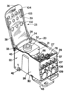
Referring initially to Figure 1 there is illustrated a power distribution
block assembly in accordance with the present invention shown generally
at 20. The metal conducting block is shown at 21 while the block is
6
CA 02504054 2005-04-11
surrounded by insulating case 22 having a hinged top cover 23 shown in
the open position.
The metal terminal block 21 shown in detail in Figures 2 through 6
is made from conductive metal such as an aluminum alloy and can be
extruded and machined. After machining the blocks may then be tin
plated to a thickness of approximately 0.05 mm.
The plastic insulation case 22 is preferably made from a plastic such
as nylon 6. The cover, however, is made of a transparent plastic material
such as polycarbonate such as sold by General Electric Company of
Schenectady, New York under its trademark LEXAN 940A. The cover may
be tinted a color such as blue, but is nonetheless fully transparent
providing visual access to the interior of the case and block when the cover
or lid is closed.
As seen in Figure 1 the case 22 comprises side walls 26 and 27, end
walls 28 and 29, and a bottom wall 30 somewhat obscured. The cover 23
may be hinged as indicated at 33 and 34 to the end wall 28 and the cover
or lid may be provided with an over-center snap to keep it in the open
position shown. The tip of the cover is provided with a snap tang indicated
at 36 which seats in snap recess 37 in the top of wall 29. The underside of
the cover or lid is provided with two projecting ribs seen at 38 and 39
which telescope inside the top edge of the case 22 blocking access to the
interior of the case when the lid or cover is closed. The insulating case is
also provided with certain projections from the bottom wall 30 indicated at
42 and 43 to facilitate the mounting of the power distribution block
assembly on an electric panel or din-rail. While each individual assembly
is a single-pole or mono-pole block, such assemblies may be ganged
together by means of the male and female dovetails shown at the sides for
convenient distribution in multi-pole systems.
7
CA 02504054 2005-04-11
Referring now additionally to Figures 2 through 6 it will be seen that
the conductive metal terminal block 21 may be formed from an extrusion
and then machined and includes a large section at one end shown
generally at 45 which includes a large socket 46 in wall 47. Extending
normal to the socket is a threaded hole 48 in the top wall 49 of the
enlarged end 45. The threaded or tapped hole 48 accommodates large
recessed head clamp screw 52 seen in Figure 1.
The large socket 46 extends through the interior wall 54 of the
enlarged end and partially into the reduced height portion 56 of the block
21. This extension of the socket beyond the wall 54 is seen at 58 in
Figure 3.
Situated in the reduced height portion 56 of the block are three tap
sockets 60 which open generally to the right hand side of the block as seen
in Figures 2 through 6. Each of the tap sockets is provided with a
transverse threaded opening in the top seen at 62, 63, and 64 for
accommodating the clamp screws indicated at 66 in Figure 1.
Projecting from the reduced height portion 56 of the block is another
offset tier of tap ports or sockets shown generally at 70 and projecting from
the intermediate tier 70 is a further offset tier 72. The intermediate tier
includes four side-by-side sockets or ports for tap connections indicated at
74 while the top tier includes four side-by-side tap connections indicated
by the sockets 75. Again, each respective socket or port is provided with a
transversely extending threaded hole as seen at 76 for the intermediate tier
70 and 77 for the top tier 72. These tapped holes in the top two tiers
accommodate the clamp screws seen at 78 in Figure 1. It is noted that the
socket in a single tier may be the same size or they may vary in size as in
the bottom tier.
8
CA 02504054 2005-04-11
Referring now more particularly to Figures 2 and 5 it will be seen
that the sockets 75 in the top tier 72 are partially blocked by the adjoining
tier 70 while the sockets 74 in the intermediate tier are partially blocked by
the portion of the block of reduced height indicated at 56.
The abutment wall at the end of each of the sockets seen at 74 and
75 is slightly beyond the interior wall of the tier and each abutment end of
the socket at such wall is provided with an inverted conic relief or scallop
as indicated at 80 for the top tier sockets and 81 for the intermediate tier
sockets. The two outside sockets in the lower most tier are partially
blocked by the wall 83 which also includes the inverted conic projection or
scallop 84 opening into sight windows 85 and 86. These sight windows are
formed in the reduced height portion of the block. The center socket in the
bottom tier is also provided with an abutment wall partially blocking the
interior of the socket and a similar scalloped or inverted conic projection
opening into the large socket for the main conductor shown at 46 and 56.
In this manner each of the tap sockets is provided with an internal
abutment wall and also a sight window enabling the tip of the conductor
inserted into the tap port or socket to be seen from the top of the assembly
through the transparent cover 23. The scallops or projections into the
abutment walls of the various tap sockets may be formed by an angled drill
point and need not be inverted circular conical sections, but may be other
shapes as well. In each of the sockets or tap ports, the abutment wall may
extend to approximately half the height of the socket opening or diameter
and the angle of the conical section may vary at its center from
approximately 15 to approximately 40 and, preferably, about 30 from
vertical.
Referring now to Figure 6 there is illustrated insulated conductors
shown at 90, 91, and 92 inserted in the respective sockets 75, 74, and 60.
9
CA 02504054 2005-04-11
The tips of the conductors with the insulation removed is seen at 93, 94,
and 95 and such tips engage the abutment end of each socket and in such
physical contact with the abutment end the tip of the respective bared
conductor indicated at 98, 99, and 100 is visible from the top of the
assembly through the transparent cover 23. Figure 6 illustrates the cover
with access ports seen at 102, 103 and 104 which are aligned with the
clamp screws of the various ports or sockets. As seen more clearly in
Figure 1 the cover or lid is provided with a total of eleven (11) ports, one
for
each of the various tap connections provided by the block 21.
Also as seen in Figure 6, the case 22 includes alignment galleries
seen at 107, 108, and 109 which assist the installer in insertion of the
bared end of the conductor into the socket and also protect against finger
insertion into the case.
Accordingly, once the main conductor is inserted and the fastener 52
tightened to activate the block and the cover or lid is closed, the assembly
is then finger-safe for installing, one, more, or all of the various tap
connections available.
Even though the insulated case is closed, as the installer makes the
connection, the installer has the benefit of both the physical abutment or
engagement of the tip of the conductor against the abutment wall and the
visual access to the tip of the conductor through the transparent lid or top.
In this manner all of the tap connections will be both uniform and
electrically correct, each with the proper uniform extent of the conductor
extending beneath and beyond the clamp screw. The operator then simple
inserts an insulated tool through the respective access openings 102, 103,
or 104 to tighten the clamp screw on the properly positioned conductor
bare end.
CA 02504054 2005-04-11
Although not illustrated, it will be appreciated that once the tap
conductors are stripped to the specified length they may be installed first
in a ferrule placed over the stripped end portion of the conductor. The
conductor or ferrule will then proceed to the abutment or bottom of the tap
hole that is partially visually exposed and visible through the transparent
cover. This visual indication of the conductor placement ensures that the
installer has both the physical abutment available as well as a visual check
to make sure the conductor is properly in place before the fastener is
secured.
Referring now to the embodiment of Figure 7 there is illustrated a
slightly smaller version of the terminal block assembly of the present
invention. The embodiment shown generally at 120 includes an insulated
case 121 with a transparent cover 122. The block within the case isn't
shown but the case is provided with alignment galleries shown at 123 and
124 to enable the bared conductor ends with or without ferrules to be
inserted into the tap receiving sockets. The clamp screw of each tap
receiving socket is provided with an access port in the cover or lid as seen
at 126 or 127.
It is noted that the cover of the embodiment of Figure 7 is provided
with a somewhat larger hole 130 which provides access to the clamp screw
for the main conductor. The cover is also provided with a somewhat
smaller hole 131 providing access to a clamp screw for another tap. In the
smaller version illustrated, the transparent cover 122 for the case may be
fixed with the somewhat larger access opening 130 provided for the
incoming line. This is in contrast to the larger embodiment of Figure 1
where the large fastener 52 for the incoming line has no access opening in
the hinged cover.
11
CA 02504054 2005-04-11
Whether the larger or smaller version of the present invention, both
are provided with transparent covers or lids which provide visual access
through the sight windows to the tips of the conductors with or without
ferrules inserted in the various tap ports or sockets against the abutment
walls forming the inner ends of such sockets.
Referring now to the embodiment shown in Figures 8, 9 and 10, it
will be seen that the case is provided with a transparent cover or lid 140.
The block and the remainder of the case is the same as shown in Figures
1-6. The inside of the cover adjacent the screw driver access holes 102 and
103 for the lower and intermediate tiers 56 and 70 of the block are
provided with paired split sleeve or tube interior projections seen at 142
and 144, respectively.
Each of the paired projections are arcuate as seen at 146 and 148
and extend downwardly toward the block 21 a sufficient distance to engage
and grip or capture the fastener in the associated threaded hole. These
tube sections on the inside of the cover are designed to let the user or
installer know when the clamp or binding screws clear the conductor tap
hole or port as shown. When the binding screw comes in contact with the
end of the tube sections, or the underside of the cover or lid for the top
tier
the respective tap hole is completely open. In addition to this gauging
function, the function of the tube sections is to retain the binding screws in
the lower and intermediate tiers should the user continue to unscrew
them. Thus the binding screws for the lower and intermediate tiers can be
backed out and disengaged from the block, but will be retained in the
respective tube sections. The tube sections in this event still keep the
binding screws aligned with the threads of the respective socket for
reinstallation without opening the lid. Accordingly, even if disengaged, the
screws are not loose in the case.
12
CA 02504054 2005-04-11
The projections may cover from about 60 to about 90 of a full circle
and the gap or split between the retainer sleeve pairs or projections shown
at 150 in Figures 8 and 10 enables a clear and unobstructed view of the
windows for the lower tier ports shown at 84, as well as the intermediate
tier ports, shown at 81, when the cover or lid is closed as shown in Figure
9. The gap or split between the paired projections extends the entire
distance from the lower or distal end of the projections seen at 154 to the
underside of the cover or lid at the respective access hole.
The inside diameter of the split retainer tube or sleeve sections is
designed to engage and grip or capture the top of the respective clamp or
binding screw as it is backed out. The projections yield slightly and grip
the top of the clamp screw as shown at 156 in Figure 10 for the screw 158.
The further the screw is backed out the tighter the grip or interference.
However, initial contact with the retainer tube sections as seen at 160 for
the screw 162 indicates that the gallery or port for the conductor is clear of
the lower tip of the screw. The projections thus not only keep the screws
from becoming loose in the case, but also may be used to gauge the fully
retracted position.
It will be appreciated that the length or extent or size of the
projections may vary depending on the size and length of the clamp screws
and their respective threaded sockets. For example, the center projection
pair for the lower tier shown at 164 may be slightly longer and smaller
than those pairs at either side shown in the row of projection 142 simply
because of the size and length of the screw 158. The same variation may
exist with the intermediate tier 70 projections 144.
As illustrated there are four sets of split sleeve or retainer tubes for
the intermediate tier, since there are four screws and sockets provided by
the intermediate tier. For the lower tier there are three split sleeve
13
CA 02504054 2005-04-11
projections, again one for each screw and respective port or socket. For the
top tier projections aren't required since the cover itself adjacent the
undersize access holes 104 would interfere with a screw backed out too far.
As seen in Figures 11 and 12, there is shown another embodiment of
the transparent cover or lid 170 which is provided with interior projections
in the form of recessed steps 172 and 174 generally corresponding to the
distal ends of the interior projections seen in the embodiment of Figures 8,
9 and 10. Again the block and the remainder of the case is the same as
shown in Figures 1-6.
The innermost step 172 is provided with three access holes shown at
176 for the binding screws of the lowermost tier, while the intermediate
step 174 is provided with four access holes 178 for the binding screws of
the intermediate tier. The top tier access holes are shown at 180 and all
are slightly smaller than the head or outer ends of the binding screws
accessed thereby. The holes permit access of a wrench or small
screwdriver but are too small for the screw itself. It will be appreciated
that the steps may be at different depths transversely of the block
depending upon the length or size of the binding screws employed.
Even though the cover or lid is transparent, the corners of the steps
may be provided with sight holes seen at 182, 184 and 186 to ensure clear
visual access to the tip of the conductor fully seated in the respective tap
ports.
In this embodiment the lid also acts to prevent loose screws in the
case and as a gauge ensuring proper conductor connection without the
necessity of opening the case.
It can be seen that the cover or lid of the embodiments of Figures 8-
12 may be used to gauge the position of the clamping screws and prevent
loose screws within the case all while providing both the visual and
14
CA 02504054 2005-04-11
physical checks for proper uniform tap connections. The invention also
provides a large capacity for power distribution but at a low cost and in a
finger-safe manner enabling the installer to make uniform proper
connections avoiding both over or under insertion of the tap connections.
Although the invention has been shown and described with respect
to certain preferred embodiments, it is obvious that equivalent alterations
and modifications will occur to others skilled in the art upon the reading
and understanding of this specification. The present invention includes all
such equivalent alterations and modifications, and is limited only by the
scope of the claims.