Note: Descriptions are shown in the official language in which they were submitted.
CA 02504590 1996-12-11
CONNECTOR ASSEMBLY FOR ATTACHMENT TO END OF CONDUIT
BACKGROITND OF THE INVENTION
Technical Field
The invention relates to quick-connect fittings for use in fluid
and vapor transmission systems and to a retainer clip for use therewith.
More particularly, the invention relates to a connector assembly including a
clip for use in vehicle fluid transmission systems. Even more particularly,
the invention relates to such a connector formed of dissimilar materials
which will limit the permeability and effusion process of certain fluids being
transmitted through the connector without sacrificing its abrasion resistance
and holding efficiency and to retainer clip for releasably securing a tubular
conduit to the connector.
This application is a division of a pending Canadian Patent
Application No. 2,263,464, filed December 11, 1996.
Background Information
In the automotive industry, as well as other industries, low-
cost, reliable and easily operated connectors are needed to provide a
connection between fluid-carrying conduits, such as fuel or refrigerant lines,
with the other componeiits of the vehicle, which can be connected easily
during assembly of the vehicle and subsequently disconnected for repair at a
later date.
1
CA 02504590 1996-12-11
Fluid transmission systems have progressed from metal
tubular lines and machined fittings to plastic tubular lines and molded
fittings, and combinations thereof. The use of plastics has grown to
the extent that it is now accepted as a standard of performance in
numerous applications. This is especially true in automotive
passenger car and truck vapor and fluid transmission systems.
In recent years, it has become necessary to develop fuel
transmission systems which are chemically resistant to an inc'reasing
variety of volatile fuel mixes, such as alcohol and methyl-alcohol
combinations. Additionally, there is an ongoing effort to reduce
significantly the system effusion of gases to the atmosphere, an effort
made even more difficult because of the new fuel mixes currently
being used more often today.
The process of transfer of gas through an aperture whose
diameter is small as compared with the distance between molecules
of the gas is known as "effusion". Many plastic materials provide
apertures or paths through the material for certain gases and block
others. The demands currently being placed on fluid transfer
systems and the resultant impact to the environment are now of such
significance that special approaches are necessary to limit this
effusion process or permeability.
Therefore, the need exists for a new family of tubular
fittings which not only embody all of the features of the current state
of the art fittings, such as quick-connection capability, swiveling, heat
resistance, easy disconnect capability, etc., but also the ability to
permit increased flow through existing tubular lines, and the ability to
significantly reduce the overall vapor effusion rate of the system.
Some examples of prior art connector assemblies and the
quick connector are shown in U. S. Patent Nos. 5,002,315,
3,997,195, 4,669,757, 4,310,185, 4,943,091, 5,261,706, 4,423,892,
2
CA 02504590 1996-12-11
4,524,995, 4,601,497, 4,681,351, 4,802,697, 4,915,136, 4,948,175,
4,979,765, 4,981,586, 5,033,513, 5,063,968, 5,067,754, 5,110,161,
5,195,787, 5,232,252 and 4,541,658.
Most of the quick connectors of the above-listed patents
s are multiple component-members which are molded of plastic or
other types of organic polymeric materials. These components are
assembled on the end of a tubular conduit having some type of
annular radially extending projection or latching member which
engages another component of the quick connector in order to
secure the connector to the tubular conduit. The other end of the
connector is generally provided with a tubular portion formed with a
plurality of external annular grooves or barbs which are force fitted
into the end of a plastic or rubber tube of the fluid transmission
system. This force is sufficient to expand the tube over the barbs or
grooves, securing the tube in place. The other end of the connector
then receives the end of the tubular member or conduit, which is then
secured by engagement of another connector component with the
annular latching projection formed integrally with the end 'of the
tubular conduit.
Although these prior art connectors perform satisfactorily
for many applications, they do possess certain inefficiencies and
disadvantages. The insertion of the tubular end of the connector
having the retaining barbs or grooves into the open end of the plastic
or rubber tube results in an inside cross-sectional area significantly
less than the cross-sectional area of the inside diameter of the tube
inserted over the tubular end of the connector. The gases and fluids
flowing through the system are sealed by the connector material only
by the effectiveness of the material to resist effusion or permeability.
These gases and fluids are sealed by the connection of the male
10 tubular extension of the connector into the inside of the tube by the
3
CA 02504590 1996-12-11
various grooves or protrusions and the interference fit with the inside
surface of the tube wall. The connector can also swivel rather easily
on the tube. Furthermore, the plastic material can "creep" as a result
of repeated hot-cold cycling to which the fluid line and connector are
s subjected, allowing leakage of the fluid therebetween.
Furthermore, these prior art quick connectors are generally
molded of a singular plastic or organic polymer material which may
for certain fluids satisfactorily resist effusion or permeability, but are
not as effective as desired for other types of fluids which will flow
therethrough. Furthermore, the multiple components of some of
these connectors increase the difficulty of connecting and
disconnecting the connector onto and from a tubular conduit than is
desirable for certain manufacturing operations and repair procedures.
Another known existing type of quick connector is shown
1s in FIGS. 14 and 15 of the application drawings. This connector
consists of a single molded member which enables the male end of
a tubular conduit having an annular latching member to be snap-fitted
therein upon insertion of the conduit into an open end of the
connector. However, the other end of the connector includes a
tubular male portion having annular projections or barbs, which is
forcible inserted into the open end of another tubular member to
provide the connection between the two tubular components. This
connection reduces the effective inside diameter as described above,
and also provides a connection which has been found susceptible to
leakage. Also, this single-component connector does not have the
required effectiveness to resist effusion or permeability for certain
types of fluids from being transferred through the connector.
It is also important that these connectors can be connected
easily during assembly of the vehicle and subsequently disconnected
for repair at a later date. These connectors require a quick connect
4
CA 02504590 1996-12-11
mechanism or clip to retain the tubular conduit within the connector.
These retainer clips must be small in size and easy to operate
because of the limited amount of space in the location where the
connectors are used. For example, in automobiles, and especially.in
front wheel drive automobiles, the amount of available space under
the hood to install and perform maintenance or repairs on these
connectors is very limited. A mechanic often has a difficult time
reaching into the area under the hood or instrument panel when
attaching the connector and to grasp and disassemble the connector
and conduit.
Several types of retainer clips are currently available which
provide a connection between fluid-carrying conduits. For example,
Patent No. 5,171,028 discloses a seal retainer with a ring-shaped
collar with a lip portion surrounding an opening of the collar and
~s extending axially therefrom. The lip portion is adapted to fit tightly
within an axial bore portion of a connector housing. Arm portions
extend from the outer circumferential positions of the collar
substantially parallel to the center axis in a direction opposite- of the
lip. The connector and conduit can be separated by depressing the
surface areas of the arms.
Patent No. 5,009,454 discloses a retainer ciip for a
swivelable quick cor.nactor assembly which includes a collar through
which the conduit passes, at least one deflectable bent leg projecting
from the collar for securing the conduit in the retainer clip and in the
connector, and a mechanism for rotationally orientating the leg with
respect to a window.formed in.the connector.
Patent No. 4,681,351 discloses a retainer clip having a
collar with an aperture for permitting passage of the conduit through
the collar. The collar includes at least two spaced deflectable legs
ao projecting from the body and a clasp secured to the legs for securing
5
CA 02504590 1996-12-11
the conduit in the retainer element and in the connector. The clasp
includes a latch with a catch for securing the clasp on the leg of the
body.
Other types of prior art retainer clips are shown in Patent
Nos. 5,104,158; 4,934,655; 5,052,725; 5,316,041 and 4,244,608.
Although these prior art retainer clips perform satisfactorily
for many applications, they do possess certain inefficiencies and
disadvantages. The projecting arms or legs occupy a relatively large
amount of space in applications where space is at a premium. An
additional amount of space is required beyond the actual space of the
retainer clip to allow a mechanic to depress the legs and disassemble
the connector assembly.
Therefore, the need exists for an improved quick connector
and connector assembly which limits the effusion process or
~s permeability of various fluids and chemicals through the connector,
yet which is easily connected and disconnected to tubular
components at both ends of the connector without subsequent
leakage or sacrificing holding efficiency.
Likewise, the need exists for an improved retainer clip for
use with these qu,ick connectors which occupies a small amount of
space, which is easily assembled in and disassembled from the
connector, which allows a conduit to be snap-fitted easily within the
connector, and which releases the conduit by merely applying
pressure to one end of the retainer clip.
SUMMARY OF THE INVENTION
. ' y
Objectives of the invention include providing a connector
which can be rapidly connected and disconnected from tubular
components of a fluid transmission system of the type especially
6
CA 02504590 1996-12-11
used in automobile passenger cars and trucks, and which
successfully {imits the effusion or permeability of various fluids and
chemicals through the material of the connector to the surrounding
atmosphere.
s Another objective of the' invention is to provide such a
connector which inGreases the flow-through by maintaining the
internal cross-sectional area of the tubular members connected to
both sides of the connector, and in addition, provides for a
satisfactory seal with the tubular components, preventing the leakage
of the transferred fluids between the connector and tubular
components.
Still another objective of the invention is to provide such a
connector which uses a plurality of elastomeric sealing members
which are mounted within the connector and engage the inserted
is tubular components to provide for a positive,, effective seal
therebetween, and yet which will permit in certain applications
movement of the connector with respect to one or both of the
connected tubular components.
A further objective of the invention is to provide such a
connector which is formed of dissimilar plastic materials, one of which
is able to. provide the chemical resistance to the fluid being conveyed
through the connector, and provide additional prot( ction from effusion,
with the other material providing the abrasive resistance and required
strength for sealing connection with tubular components connected
to one or both ends of the connector.
7
CA 02504590 2006-04-19
Objectives of the invention include providing an improved retainer clip
for quick connect fittings of the type used in vehicle fluid systems which
occupies a
relatively small amount of space around the periphery of a receiving end of a
connector into which an end of a conduit is slidably inserted.
A farther objective of the invention is to provide such a retainer clip
which is relatively easy to assemble and disassemble with and from the
connector,
and which has a chamfered surface on one side to allow a conduit to slide
easily into
the connector and has a flat latching edge to retain the conduit therein.
Another objective of the invention is to provide such a retainer clip
which allows the conduit to be easily released from the connector by applying
a
slight amount of pressure to one end of the clip, and which has a flexible tab
which
slides into a slot formed in the connector to insure that the clip is properly
installed
on the connector whereby the chamfered entrance surface of the clip is facing
the
correct direction for receiving the end of the tubular conduit.
One form of the invention resides in a connector for attachment to the
end of a conduit; and a clip engageable with the connector for retaini.ng the
conduit
within the connector. The connector has a curved outer surface and is formed
with a
bore therethrough, the connector being adapted to receive the end of the
conduit
within the bore, and further includes a pair of opposed apertures formed in
the outer
surface; the apertures communicating with the bore. The clip has a pair of
opposed
first and second ends connected by a pair of spaced sides forming an elongated
opening therebetween; which opening is adapted to receive the conduit
therethrough.
The clip includes a pair of curved flexible fingers extending outwardly away
from the
first end of the clip and extending toward the second end thereof; each of the
fingers
being disposed a spaced distance away from one of the sides of the clip. A
chamfered surface is formed in an inner edge of the second end of the clip to
permit
8
CA 02504590 2006-04-19
the passage of the end of the conduit between the sides and through the
elongated
opening after the clip has been mounted in the apertures; so that the flexible
fingers
slidably engage the outer surface of the connector and bias the clip toward a
locked
position with the conduit.
The present invention further resides in a connector for atta.chment to
the end of a conduit wherein the conduit has a radially extending latching
member
spaced inwardly from an outer end of the conduit, and wherein a clip is
engageable
with the latching member for retaining the conduit within the connector. The
connector is formed with a stepped bore and a pair of opposed apertures
communicating with the bore. The clip is an integral one-piece rigid plastic
member
having first and second ends connected by a pair of spaced sides and forming
an
elongated opening therebetween and extending between the ends. The opening
includes an enlarged portion sufficiently large to permit the latch member of
the
conduit to pass therethrough and a smaller portion which prevents passage of
the
latch member therethrough. A pair of curved flexible fingers extend outwardly
from
the first end and toward the second end, and each finger is disposed a spaced
distance
from one of the sides of the clip. The first and second ends slidably engage
an outer
surface of the connector to bias the clip toward a locked position with the
conduit
wherein the tubular conduit extends partially through the smaller portion of
the clip
opening. A chamfered surface is formed in an inner edge of the second end and
is
engageable by the outer end of the conduit to move the clip toward an unlocked
position and overcome the bias of the flexible fmgers to permit the passage of
the end
of the conduit between the sides and through the enlarged portion after the
clip has
been mounted in the apertures.
More specifically, a pair of nubs may be formed on outer ends of the
flexible fingers and engage outer curved surfaces of the connector for biasing
the clip
toward the locked position with the conduit.
9
CA 02504590 2006-04-19
In one embodiment of the invention a flexible tab extends outwardly
from an other of the ends of the clip; and in which the flexible tab engages
the
connector for securing the conduit within the connector.
More specifically the elongated opening may include a lower reduced
diameter arcuate portion adjacent the other end of the clip and a generally
larger
diameter circular center portion, and an elongated slotted portion extending
between
the center portion and the one end of the clip.
Also, the sides of the clip may have generally flat outer edges which
are parallel to each other.
15
25
CA 02504590 1996-12-11
BRIEF DES iPTiON OF THE DRAWINGS
Preferred e,r,rmbodiments of the invention, illustrative of the
;. .
best modes in which" applicants have contemplated applying the
principles, are set forth in the following description and are shown in
the drawings and are particularly and distinctly pointed out and set
forth in the appended claims.
FIG. 1 is a side elevational view of the outer member of a type of
connector in which the present invention may be utilized with certain internal
features being shown in dash lines;
FIG. 2 is a top plan view of the outer member of the connector of
FIG. 1.
FIG. 3 is a right side end elevational view of FIG. 1;
FIG. 4 is a side elevational view of the inner member of the
connector with internal features shown in dash lines;
FIG. 5 is a top plan view of FIG. 4;
FIG. 6 is~ a'right-hand elevational view of FIG. 4;
FIG. 7 is an enlarged sectional view of the connector
consisting of the inner-and outer members of FIGS. 1-6 in assembled
position with two tubular components being shown just prior to
assembly with the connector;
FIG: 8 is a sectional view similar to FIG. 7, with the two
tubular components shown in assembled position with the connector;
FIG. 9 is a;on diagrammatic plan view showing the initial
steps of a method of molding a plurality of the connector of FIGS. 1-8;
11
CA 02504590 1996-12-11
FIG. 9A is a top diagrammatic plan view similar to FIG. 9,
showing the completion of the molding of three connectors
and their removal from the mold cavities;
FIG. 10 is an enlarged fragmentary diagrammatic view of
one of the mold cavities of FIG. 9;
FIG. IOA is a fragmentary diagrammatic view similar to
FIG.10, showing the injection molding of the outer member about the
inner member of one of the connectors within the mold cavity;
FIGS. 11, 11A and 11 B are fragmentary sectional views
showing other types, of tubular members connected by various
arranaements to the-carinector of FIGS. 1-10;
FIG. 12 is a sectional view similar to FIG. 8, showing a straight-
through connector configuration with two tubular members connected
thereto;
FIG. 12A is an elevational view of the inner member of the
connector of FIG. 12;
FIG. 13 is a sectional view similar to FIGS. 8 and 12,
showing another embodiment of the connector;
FIGS. 14' and 15 are sectional views of two prior art
connectors;
FIG. 16 is a sectional view of a modified connector consisting of
inner and outer members in assembled position in accordance with the
present invention with one tubular component being retained therein, and
with a second tubular component being shown just prior to assembly with the
connector;
12
CA 02504590 1996-12-11
FIG. 17 is a sectional view similar to FIG. 16 showing the
two tubular components in assembled position with the connector;
FIG. 1.8 is a greatly enlarged fragmentary sectional view of
' the encircled portion of FIG. 17;
FIG. 19 is a perspective view showing the connector of FIG. 16
with the retaining clip being inserted therein in accordance with the present
invention. FIG. 19A is a plan view of the retaining clip of FIG. 19;
FIG. 20 is a perspective view similar to FIG. 19 showing the
retainer clip in position within the end of the connector;
FIG. 21 is a sectional view of the connector and clip of FIG.
20 retaining a tubular component therein;
FIG. 22 is a sectional view taken on line 22-22, FIG. 21;
FIG. 23 is sectional view similar to FIG. 21 showing the clip
. . .,.
moved to the tubulair component release position;
FIG. 24 is a diagrammatic view, with portions in section,
showing the manner of molding the outer member over the inner
member to form the connector of -FIG. 19;
FIG. 25 is a sectional view similar to FIG. 16 showing a
modified form of the connector; and
FIG. 26 is a sectional view similar to FIGS. 16 and 25
showing another embodiment of the connector of the present
invention.
Similar numerals refer to similar parts throughout the
drawings.
13
CA 02504590 1996-12-11
QE5CRIPTION OF THE PREFERRED EMBODIMENTS
A first embodiment of a connector is indicated generally at 1,
io and is shown particularly in FIGS. 1-8. Connector 1 consist of two main
components, inner and outer members, indicated generally at 2 and 3,
respectively, and shown in FIGS. 4- 6 and 1- 3, respectively.
Inner member 2 in the first embodiment, is a 90 elbow and
is iricludes a first tubular portion 5 and a second tubular portion 6
. ~.
oriented 90 with respect to each- other. Tubular portions 5 and 6
'terminate in outer annular flanges 7 and 8, respectively. Referring to
FIG. 7, inner meinber 2 is formed with a right-angle bore 10, which is
comprised of bore sections 11 and 12 formed in tubular portions 5
20 and 6. End flanges,7 and 8 are formed with inner annular shoulders
14 and 15, respectively, in which are seated elastomeric 0-rings 16
and 17, -respectively. In the preferred embodiment, 0-rings 16 and
17 are formed of a. fiuorosilicone. Inner bore portions 11 and 12 are
separated by an irrner annular flange 18 which defines an opening
zs . 19, which provides fluid communication between bore.portions 11
and 12.
'~.
' '. Outer member 3 (FIGS. 1-3 and 7) has a right-angle
configuration si9'lar to that of inner member 2, and completely
encapsulates Inner member 2. Outer member 3 is formed with an
30 ~ inner annular groove 21 in which is seated outer annular flange 8 of
14
CA 02504590 1996-12-11
inner member 2, and a second annular groove 22 in which is seated
outer annular flange 7 of inner member 2. These grooves assist in
securing inner member 2 within outer member 3. Outer member 3
includes a tubular bore portion 24 which extends from an outer open
s end 25, and is similar in diameter to the inner diameter of bore portion
11 of inner member 2. The other end of outer member 3 includes a
cylindrically extending end wall 26, which defines a second open end
27. Cylindrical end wall 26 has an internal diameter generally equal
to the internal diameter of bore portion 12 of tubular portion 6 of inner
member 2, which preferably is equal to the internal diameter of bore
portion 11 of tubular portion 5.
In accordance with one of the features of the invention, a
pair of latching members 30 are formed integrally on the end of outer
member 3, and, in particular, with that portion of outer member 3
is which forms tubular bore portion 24. Each latching member 30
includes a latching leg or finger 31 which is pivotally mounted to outer
member 3 by an integrally formed pivot 32. The forward end of each
latching member 30 includes a tapered camming surface 34-, which
terminate in arcuate latching shoulders 35. The inward ends of
latching members 30 include thumb and finger-engaging portions 38,
which, when depressed, will pivot latching shoulders 35 outwardly
about pivots 32. A thin flexible strip of material 39 may extend from
outer member 3 to the ends of each of the latching members 30 to
provide a biasing force on latching members 30, biasing latching
shoulders 35 toward each other and into a latching position. An
arcuate groove 40 is formed in each finger 31 adjacent open end 25
of outer member 3 to provide for the reduced thickness of material to
form pivots 32.
A tubular member 42 is inserted into open end 27 of
cylindrical end wall 26, and secured therein, as described further
CA 02504590 1996-12-11
below, when forming a connector assembly 46, as shown in FIG. 8.
In accordance with one of the features of the invention, tubular
member 42 will be formed with multiple walls, and in the embodiment
shown in the drawings, will have inner and outer walls 43 and 44 and
s an intermediate wall 45 sandwiched therebetween. As an example,
inner and outer walls 43 and 44 will be formed of Nylon 6, with
intermediate wall 45 being formed of an acetal, such as polysulfide.
Intermediate wall 45 will provide an efficient barrier to the
effusion or permeability of the various chemicals and gases,
preventing their escape into the surrounding atmosphere. Inner and
outer walls 43 and 44 will provide the strength and abrasion
resistance needed for the tubular member. However, it is readily
understood that tubular member 42 could consist of only an outer
wall formed of a material such as Nylon 6 to provide for the strength
ls and abrasion resistance, with only a single inner wall to prevent the
effusion or permeation of the gases through the tubular member.
Furthermore, the tubular member 42 could be formed of even a
greater number of walls than the three shown in the preferred
embodiment and described above, without affecting the concept of
the invention.
Tubular member 42 preferably will have a short portion of
its outer wall 44 stripped away, whereby the intermediate and inner
walls 45 and 43 Will extend beyond 0-ring 17 until abutting annular
inner flange 18 to fully seat the end of tubular member 42 within inner
and outer members 2 and 3. However, for certain applications, outer
wall 44 could extend completely within bore portion 12 of tubular
portion 6 of inner member 2.
Connector assembly 46 will further include a tubular
conduit, indicated generally at 47, which for many applications will be
formed of metal. Conduit 47 has an annular radially extending
16
CA 02504590 1996-12-11
latching projection 48, and a male cylindrical end 49 terminating in a
tapered outer tip 50. As shown in FIG. 8, male end 49 is inserted
through open end 25 of outer member 3 and beyond 0-ring 16 and
into bore portion 11 of inner member 2. Annular latching projection
s 48 slides along tapered camming surfaces 34, spreading latching
members 30 outwardly until latching member 48 moves beyond cam
surfaces 34 and snaps into position with latching shoulders 35, in
which position latching members 30 return to their latching position,
securing tubular member 47 in connector 1. Strips 39 will assist in
biasing latching members 30 to their latch-engaged positions with
latching projection 48, as shown in FIG. 8, to retain tubular member
47 in its latched position within inner and outer members 2 and 3. As
shown in FIG. 8, a portion of male end 49 will sealingly engage 0-ring
16 and, preferably, will be in a sliding engagement with the inner
cylindrical surface which defines bore portion 11 of inner member 2.
As can be seen in FIG. 8, the internal cross-sectional area
of tubular member 42 a,1d of tubular conduit 47 are maintained, and
are not restricted in any manner due to their connection with
connector 1, as in prior connectors for similar applications.
It is easily seen that upon pressing inwardly in the direction
'of arrows A on latching members 30, latching shoulders 35 will
disengage annular latching projection 48 of tubular conduit 47,
enabling the conduit to be removed easily from within connector 1 for
repair or replacement.
In accordance with another feature' of the invention,
connector I and cojinector assembly 46 are manufactured by an
improved method, as shown particularly in FIGS. 9, 9A, 10 and 10A.
Inner housing 2 is preformed of the desired plastic material, and 0-
rings 16 and 17 are inserted within their respective retaining grooves
21 and 22. Next, the end of tubular member 42 is prepared, for
i~
CA 02504590 1996-12-11
example, in the Preferred embodiment, by removing a short section
of outer wall 44, after which the exposed portion of intermediate wall
45 and inner wall 43 is inserted completely within cylindrical end wall
26 of outer member 3 until it abuts against inner flange 18. This
s subassembly is then placed within a cavity 52 formed in a mold base
53 (FIGS. 9 and 10), with tubular member 42 extending beyond mold
cavity 52. Next, a mandrel 54 is inserted through tubular bore portion
24 of outer member 3 and into bore portion 11 of inner member 2 to
prevent the flow of molten plastic material into bore portion 11.
A conventional horizontal-fill vertical clamp injection
molding machine preferably is utilized in forming connector assembly
46. The machine includes a horizontal sliding table 55, with two or
more mold bases 53, and is referred to in the industry as "shuttle
molding". The process requires two mold bases 53 and one mold top
~s 57. Multiple mold cavities 52 may be used, three of which are shown
in the drawings. The number of cavities will depend upon machine
molding capacity versus load-unload mold time. Plastic material 58
which forms outer member 3 flows through an inlet opening 59
formed in mold base 53 (FIG. 10A) until it fills the cavity surrounding
the subassembly and after cooling forms outer member 3, which
completely encases inner member 2 and secures tubular member 42
within inner member 2. The machine cycles and the mold opens by
removal of mold top 57, and the loaded mold base moves horizontally
to the left-hand position of FIG. 9A where the three molded
subassemblies are removed from mold cavities 52 and the loading
cycle is then repeated, as shown in the right-hand portion of FIG. 9.
Connector 1 can also be used very readily with other types
of hoses and/or tubes of a construction other than that described
above for tubular member 42. As shown in FIG. 11, a modified
tubular member 60 is shown molded within cylindrical end wall 26 out
18
CA 02504590 1996-12-11
of outer member 3. Member 60 has an inner wall 61 formed of a
single layer of plastic which projects into inner member 2 and abuts
against annular flange 18. An outer braided layer 62 of steel wire is
stripped away a short distance from the end of tubular member 60,
and preferably terminates adjacent 0-ring 17. This provides a
connector adaptable for use in fluid transmission systems containing
relatively high internal pressures gas= or fluid pressures.
FIG. 11A shows a modified connector 1A, which is similar
to connector 1 described previously, with the exception that an inner
sleeve or tube 63 is molded integrally with annular flange 18 of inner
member 2. Sleeve 63 extends axially within bore portion 12, and
forms an annular recess 64 thereabout, into which the end of tubular
member 42 is inserted. Another modification of connector 1A is the
formation of an annular protrusion 68 on tubular member 42 generally
adjacent the open end thereof. Protrusion 68 assists in retaining
tubular member 42 within cylindrical end wall 26 of connector 1A
when molded therein in a similar manner as discussed above and
shown in FIGS. 9-1OA. Inner sleeve 63 assists in reducing "creep"
of member 42 and fluid leakage around 0-ring 17 by more securely
trapping the end of inember 42 between inner sleeve 63 and inner
member 2. This enhances the sealing relationship between tubular
member 42 and 0-ring 17. In forming inner sleeve 63, a mandrel
would be inserted,within the open end of inner member 2 when
molding the same.
Another modification to the connector of the present
invention is indicated at 113, and is shown in FIG., 11 B. This
embodiment is similar to connectors 1 and 1A, with the main
difference being th~t an inner sleeve 63B is provided, similar to
sleeve 63 except that it extends completely through and slightly
beyond bore portion 12 of inner member 2. Sleeve 63B provides an
19
CA 02504590 1996-12-11
annular recess 64B surrounding sleeve 63B for receiving the end of
tubular member 42. Sleeve 63B also provides reinforcement for
tubular member 42 to resist injection molding pressure.
Another modification in connector assembly 1 B of FIG. 11 B
s is the use of a one-way metal lock washer 69 which is slid along the
outer end of tubular member 42 prior' to placing member 42 and inner
member 2 in mold cavity 52. When outer member 3 is molded about
inner member 2 and a portion of tubular member 42, washer 69 forms
a more secure bond with outer member 3 to prevent member 42 from
pulling out of the open end of connector 1 B. A steel mandrel would
be inserted within the open end of inner member 2 when molding
inner member 2. -
FIGS. 11, 11A and 11 B show that various arrangements
can -be provided at the open end of the connector opposite the quick
1s connect end, when forming the connector assembly. This provides
for either moldinga tubular member 42 thereon or, in the alternative,
provides an open. 'end or annular recess therein into which the end of
tubular member 42 can be slidably inserted after the connector has
been molded and subsequently secured by an adhesive, sonic
welding or other arrangement for forming a fluid-tight, anti-creep
connection therebetween. It is readily understood that connectors 1,
1A and 1B could be formed with other end configurations so that a
tube or pipe could be secured by conventional threads, compression
fittings, etc. without affecting the concept of the invention.
The insert molding process of the present invention also
makes it feasible to significantly increase the strength of complex
fittings through the redundancy of layers and materials offered. For
example, glass-filled Nylon is not a good candidate for fittings,
because the glass fiil provides pass-through material, increasing the
potential for effusion. However, it can be used in the present method
CA 02504590 1996-12-11
and connector assembly as one of the outer layers, providing
exceptionally high overall strength, since an inner or intermediate
layer of a dissimilar material will provide a barrier to prevent effusion.
Another embodiment of the present invention is indicated
generally at 65, and shown in FIG. 12. Connector 65 is similar in
most respects to connector 1, with the main difference being that
inner member 66 (FIG. 12A) is formed as a straight cylindrical
member instead of a 90 elbow, as is inner member 2 of connector 1.
Likewise, when an outer member 67 is molded about inner member
66, it will also assume a straight cylindrical configuration, trapping
inner member 66 therein, and providing a straight through-path for
the fluid or gases flowing through tubular member 42 and tubular
conduit 47. The other features and components of inner and outer
members 66 and 67 are the same as those described above with
respect to connector 1.
A further embodiment of the improved connector and
connector assembly is shown in FIG. 13, with the modified connector
being indicated at 70. Connector 70 is generally similar to that of
connector 65, described above and shown in FIG. 12, in that it
provides for a straight flow-through path of the liquid or gas, and is
shown connected to two tubular members 42, although it could be
connected to one or two tubular conduits 47, if desired. Connector
70 includes a third inlet port 71 formed in the outer member 72 by a
cylindrical wall 73, in which is contained a cylindrical wall 74 of an
inner member 75. Inner member 75 is similar to inner member 66
described above, except for the inclusion of cylindrical wall portion 74
extending normal to the main cylindrical body of the inner member.
Cylindrical wall 74 is formed with an opening 77 in which a valve (not
shown) can be mounted, which valve enables measurements to be
made of the pressure level of the fluids flowing through the connector
21
CA 02504590 1996-12-11
and conduits 42.
It is readily seen that other types of connector constructions
can be utilized. For example, the connector shown in FIG. 13 could
be a T-connector, with the check valve being replaced with another
s tubular member 42 or tubular conduit 47. Again, as shown in FIGS.
12 and 13, the improved connector of the present invention provides
a connector in which the inner member is formed of a dissimilar
material than the outer member, which substantially encases the
inner member: This enables the inner member to be formed of a
material which is able to withstand corrosion and harmful effects of
the various fluids flowing through the connector, and, more
importantly, eliminates effusion of the various vapors from permeating
through the connector and into the surrounding atmosphere.
Likewise, this enables the outer member to be formed of a more rigid,
i5 abrasive-resistant material able to withstand the harsh environments
to which the connector may be exposed, as well as providing the
required structural strength for connectiori to the various tubular
}
members adapted to be connected therewith.' Likewise, the improved
connector does not reduce the inside diameter of the connected
tubular members, and by the use of the elastomeric 0-rings, prevents
the escape of fluids from between the connector and tubular
members.
If desired, multiple 0-rings can be utilized to further
increase the sealing connection between the connector and tubular
members without affecting the concept of the invention or the
improved results achieved thereby. As shown in FIGS. 8, 11 and 12,
0-ring 17 bears directly on the intermediate wall of tubular conduit 42
or the inner layer of tubular conduit 60 to prevent leakage around the
end of the tube and between the layers under the 0-ring seal. The
amount of this leakage may be so minute that it is insignificant and it
22
CA 02504590 1996-12-11
may not be necessary to strip the outer tube layer for many
applications. The improved connector also can allow tubular conduit
47 to swivel or rotate with respect to the connector while still retaining
its seal with elastomeric 0-ring 16. Staking or marking the tube at a
s point on its circumference in the mold area can prevent swiveling
from occurring, if desired. Furthermore, the "creep" problem
described previously present in many existing connectors is
effectively resolved by the use of the elastomeric high-strength seals
16 and 17 incorporated into the improved connector.
FIGS. 14 and 15 show two prior art connectors 79 and 79A
of which the present is an improvement thereon. Both of these
connectors are provided with latching members formed integrally with
the main body 83 of the connector. However, the main bodies of
these connectors are formed of a single layer of plastic material,
~s preferably glass-filled Nylon, in order to provide the required strength
for coupling with a tubular conduit 85 and for insertion into the open
end of a tubular member 86 which is retained thereon by the plurality
of barbs 81 formed on the cylindrical wall portion 82 thereof.
However, nothing is provided in either of these prior art connectors
which will reduce the effusion of vapors from the fluid flowing
therethrough to the surrounding atmosphere, nor provide for a
satisfactory connection at the opposite end of the connector from that
of latches 80, which does not reduce the cross-sectional area of the
tubular member nor provide a satisfactory seal therewith, as does the
connector of the present invention, described previously.
Another embodiment of the connector of the present
invention, is indicated generally at 90 and is shown in FIGS. 16 - 20.
Embodiment 90 includes inner and outer members indicated
generaliy at 91 and 92, respectively, both of which are 900 elbows
with inner member 91 being surrounded by and encapsulated within
23
CA 02504590 1996-12-11
outer member 92, as discussed further below. Inner member 91
includes a right'angled bore 93, having an open first end 94 and an
open second end 95, which open ends coaxially aligned with open
ends 96 and 97, respectively, of outer member 92. A first sealing 0-
ring 99 is mounted within an annular stepped shoulder 100 adjacent
open end 94 of inner member 91, and a second elastomeric 0-ring
102'is mounted within an annular step shoulder 103 formed in inner
member 91, adjacent open end 95. A, cylindrical sleeve 105,
preferably is formed integral with inner member 91 and extends
axially within the bore thereof and extends beyond open end 97 of
outer member 92, as shown in FIGS. 16 and 17. Sleeve 105 forms
an annular recess 107 between the sleeve and the inner adjacent
cylindrical surface of outer member 92.
In accordance with another feature of the invention a one-
is way metal washer or retaining ring 110 is seated against annular
shoulder 103 adjacent 0-ring 102. Washer 110 is an usual annular
metal ring having, a slightly curved inner edge as shown if FIG. 18,
which permits the passage of a rod or tube therethrough in a first
direction, as indicated by arrow C in FIG. 18, yet retards or prevents
movement of the rod or tube in the opposite direction through the
washer.
In furttyer accordance with the invention, connector 90 is
formed with a unique latching end indicated generally at 111, formed
adjacent open end 96 of outer member 92. Latching end 111
includes a cylindrical shaped front housing 112 formed with a
stepped bore. Housing 112 may have various outer surface shapes,
including an enlarged diameter front cylindrical portion 113 and a
reduced diameter cylindrical rearward portion 114. A pair of similar
opposed apertures 115 are formed in reduced diameter portion 114
and have an arcuate shape for receiving an improved retaining clip
24
CA 02504590 1996-12-11
120 therein. Each aperture 115 has an arcuate length of
approximately 115 and are separated from each other by
diametrically opposed arcuate sections 114A of cylindrical portion
114, which have parallel spaced inner surfaces 116 as shown in
FIGS. 21 and 23. Sections 114A each have an arcuate length of
approximately 65 . Sections 114A secure clip 120 within housing
112, when clip 120 is an inserted position therein, as shown in FIGS.
20 and 21 and described further below.
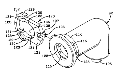
Clip 120 (FIGS. 19 and 19A) is a rigid one-piece member,
preferably molded of a high strength plastic material. Clip 1 includes
a pair of diametrically opposed arcuate end members 121 and 122,
which are connected by spaced generally parallel sides 123. End
members 121 and 122 and sides 123 form an elongated inner
opening 125. A flexible guide tab 126 is form integraliy with end 121
~s and extends outwardly in a stepped relationship therefrom and
includes a latching shoulder 127. End members 121 and 122 and
sides 123 form a relatively rigid member in contrast to prior art clips
having flexible legs which expand and contract to capture a
conducted therebetween.
A pair of curved flexible fingers 129 extend outwardly from
end 122 and include a partially circular nub 130 on an inner surface
therefore adjacent the extended ends. Two pairs of partially circular
shaped recess 131 and 132 are formed at the junction of each finger
129 and end member 122 to provide increased flexibility between the
fingers and the end member. A chamfered surface 134 is formed in
a front inner edge of end member 121 to allow a conduit to slidably
pass therethrough, as discussed further below. As shown in FIGS.
19A and 21,sides 123 of clip 120 have generally flat outer edges 136,
which extends parallel to each other. Furthermore, elongated inner
opening 125 (FIG. 19A) includes a reduced diameter arcuate portion
CA 02504590 1996-12-11
137 adjacent arcuate end 121, which communicates with a larger
diameter generally circular center portion 138, which merges into a
slotted portion 139, which terminates at end member 122.
s Referring to FIG 16 - 18, a tubular member 140 is shown
seated within annular recess 107 formed between sleeve 105 and
inner and outer members 91 and 92 and is secured therein by
retainer ring or washer 110. Tubular member 140 is shown as a
mono-wall tube, although it is readily understood that it could be a
3.0 multiple-wall member as shown in and discussed previously above.
Tubular member 140 can be slidably inserted easily into recess 107
by applying a manual force thereto in the direction of arrow D, where
it forms a fluid tight seal with 0-ring 102 and is locked in position by
retainer ring 110: Thus no additional attachment means of any type
15 is required to secure member 140 to connector 90, and sleeve 105
provides reinforcement to the connected end of member 140 and
prevents possible loosening of the fluid tight seal therein, which can
occur due to "creep", in the plastic material over an extended period
of time.
20 Tubular conduit 47 is installed easily within open end 94 of
inner member 91 and open end 96 of outer member 92 by first
inserting clip 120 into apertures 115 of front housing 112 of latching
end 111, as shown in FIGS. 19 - 23.
The thickness of end members 121 and 122 and of sides 123 is just
25 slightly less than the wide of apertures 115, and the distance
between the outer flat edges of side 123 is slightly less than the
diametric distance between the parallel inner surfaces 116 of
apertures 115 as best shown in FIGS. 21 and 23, to permit clip 120
to be slidably inserted through the apertures into the position shown
30 in FIG 20. When inserting clip 120 through apertures 115, flexible tab
26
CA 02504590 1996-12-11
126 will move through a pair of diametrically opposed and aligned
guide channels 128 (FIG. 19) formed in cylindrical portion 114 of
housing 112. Guide tab 126 ensures that clip 120 can only be
installed so that chamfered surface 134 faces outwardly for receiving
s tapered outer end .50 of tubular conduit 47 when inserted into the
connector. However, it is readily seen and understood that clip 120
can be inserted from either direction into connector 90 due to the
formation of the pair of opposed channels 128. However, regardless
of which'direction clip 120 is inserted through apertures 115, tab 126
ensures that the chamfered surface is always facing outwardly for
receiving the tapered end of tubular conduit 47.
To lock tubular conduit 47 within connector 90, clip 120 is
forced in the direction of force arrow F (FIG 23) so that enlarged
generally circular center portion 138 of elongated opening 125 is
is coaxial with open end 96 of outer member 92. Thus enables annular
latching flange 48, which has a diameter approximately equal to that
of central portion 138, to pass therethrough with a generaliy tight
sliding fit, until end portion 49 is seated within the bores of inner and
outer members 91 and 92 in a fluid sealing engagement with 0-ring
99 as shown in FIGS. 16 and 17. Upon the release of force F on end
member 122 of clip 120, the flexibility of fingers 129 will bias the clip
to the Iock position'of FIG. 21 wherein the smaller reduced diameter
portion 137 of inner opening 125 moves into engagement with
conduit portion 49 and behind annular latching projection or flange 48
to lock conduit 47 therein. To remove conduit 47 from within
connector 120, the reverse operation is performed. Namely force F
is reapply to end member 121 as shown in FIG. 23, depressing
fingers 129 with nubs 130 moving along cured surfaces 114A
providing a camming action therebetween, enabling the conduit to be
ao pulled in the direction of arrow G (FIG. 17), whereby annular flange
27
CA 02504590 1996-12-11
48 moves throu'gh the complementary shaped and equal diameter of
central portion 138 of clip opening 125.
Flexible tab 126 snaps behind an edge 133 of cylindrical
portion 114 (FIG. 22) when clip 120 is in the locked portion with
tubular conduit 47, to securely retain the clip in the locked position.
Tab 126 is merely pushed inwardly in the direction of arrow H, FIG.
22, to release its engagement with edge 133 permitting clip 120 be
moved to the unlocked position where enlarged central portion 138
aligns with the connector bore.
In accordance with another of the features of the invention,
inner member 01 may contain imbedded carbon or other types of
material, which renders the inner member and sleeve 105 as an
electrical conductive material. This will provide a continuous
electrical flow path from tubular conduit 47 to tubular member 140 to
prevent the build-up of static electricity, which could become a
problem, when the connector is used in fuel line applications.
Likewise, as discussed previously, the low permeation of the
conductor and in particular the formation of inner member 91 of
various low porosity materials, reduces the escape of gases into the
atmosphere, while permitting outer member 92 to be formed of a
scuff and abrasive resistance material. Likewise, the elastomeric 0-
rings provide a fluid tight seal with the tubular conduit and tubular
member, also preventing the escape of vapors and gases into the
.atmosphere. Also, retaining ring 110 holds tubular member 140
firmly in the connector by the simple insertion of the tubular member
into recess 107, eliminating the need of additional attaching
components.
The improved method of molding connector 90 is shown in
FIG. 24 and is similar in many respects to the method described
above and shown in FIGS. 9- 9A. Inner member 91, which can be
28
CA 02504590 1996-12-11
molded at a remote site, is placed within a cavity 141 of a mold 142,
and a mandrel 144 is inserted into the bore of inner member 91. A
two-piece mandrel indicated generally at 145, which includes an outer
hollow cylindrical mandrel portion 146 and a cylindrical inner portipn
s 147 is inserted into recess 107 and the hollow interior 148 of sleeve
105, respectively, to prevent sleeve 105 from collapsing, when the
material resin indicated at 149, flows into the mold cavity and around
inner member 91 through mold gate 150. The incoming resin
completely surrounds and encapsulates and traps inner member 91
within the newly formed outer member 92.
Prior to injecting the molten resin into mold cavity 141, 0-
rings 99 and 102 are placed in position along with metal retaining ring
110. Ring 110 forms a pocket for the 0-ring and protects it from the
incoming molten resin, when outer member 91 is being molded.
is After plastic material 149 sufficiently hardens around inner
member 91, mandrels 144 and 145 are removed, enabling the
complete connector to be removed from mold 142 which then
contains the two sealing 0-rings and metal retaining ring trapped
therein, for subsequent shipment and installation at a remote. site. If
desired, the molding of outer member 92 can be accomplished as
discussed above and shown in F1GS.10 and 10A, that is, with tubular
member 145 being attached to the connector in the mold cavity.
Metal retaining ring 110 will enable tubular member 140 to
be inserted into and automatically secured in the open end of the
connector after the connector has been molded, whether tubular
member 140 is metal or a synthetic plastic material. Likewise it is
readily understood that inner sleeve 105, which is desirable for many
applications, can be eliminated without effecting the concept of the
invention. In such a modified construction, mandrel 145 will be a
single piece mandrel, which will provide the necessary internal
29
CA 02504590 1996-12-11
reinforcement during the molding of outer member 92.
Another embodiment of the improved connector of the
present inventionis indicated generally at 155, and is shown in FIG.
25 and is similar in many respects to embodiment 70 shown in FIG.
s 13, with the exception that end 156 is provided with the above
discussed metal retaining ring 110 and associated 0-ring 102, for
securing tubular member 140 therein with a slip-fit engagement.
Connector end 157 is similar to end 111 of FIG. 16 and receives and
secures end 49 of tubular conduit 47 therein by the use of clip 120.
Connector 155 includes a third inlet opening, which is formed by a
pair of radially extending and aligned openings in the inner and outer
members, which communicates with the interior bore of the
connector, to provide a service port for the connector. Opening 159
may have an air valve 160 mounted therein, and may contain an end
is sealing cap 161 threadably engages therewith.
Another modified connector is indicated generally at 165,
and is shown in FIG. 26 and is generally similar to connector 90
shown and described above, except that it is a straight connecter
wherein the bore extends in a linear direction completely through the
connector, whereas connector 90 is a 900 elbow. The ends of
connector 165 are the same as that described above with respect to
connector 90 for receiving and securing tubular member 140 therein
by retaining ring 110, with tubular conduit 47 being retained therein,
by-clip 120.
It is easily seen that either end of the various connectors
shown in FIGS 16, 25 and 26 could have other types of fittings, such
as a screw connection or the like, without effecting some of the main
features of the invention, such as the molding of the connector as a
two-piece member, with one of the members being formed of a
different plastic than that of the other member to provide the
CA 02504590 1996-12-11
resistance to the permeation of the fumes therethrough, while
providing the desired physical protection in abrasion resistance as in
prior plastic type connectors.
Accordingly, the connector, and connector assembly and
clip of the present invention are simplified, provide an effective, safe,
inexpensive, and efficient device and method which achieves all the
enumerated objectives, provide . for eiiminating difficulties
encountered with prior devices and methods, and solve problems and
obtain new results in the art.
In the foregoing description, certain terms have been used
for brevity, clearness and understanding; but no unnecessary
limitations are to be implied therefrom beyond the requirement of the
prior art, because such terms are used for descriptive purposes and
are intended to be broadly construed.
is Moreover, the description and illustration of the invention
is by way of example, and the scope of the invention is not limited to
the exact details shown or described.
Having now described the features, discoveries and
principles of the invention, the manner in which the improved
connector and connector assembly are constructed and used, the
characteristics of the construction, and the advantageous, new and
useful results obtained; the new and useful structures, devices,
elements, arrangements, parts and combinations, and method steps,
are set forth in the appended claims.
.,~
31