Note: Descriptions are shown in the official language in which they were submitted.
CA 02504676 2005-05-02
ACTUATOR WITH A SIMPLE FUNCTION HAVING A QUICK-OPENING
HYDRAULIC VALVE FOR THE CONTROL OF A CLUTCH
The invention relates to an actuator with a simple
function for the control of a friction clutch in the drive
train of a motor vehicle having a cylinder/piston unit for
generating the contact pressure of the clutch, in
conjunction with which a controllable electric motor/pump
unit provides a pressure medium and is connected to the
cylinder/piston unit via a self-regulating valve unit, so
that the clutch is controlled by actuating the pump. The
invention can thus relate both to clutches for locking a
differential and to clutches for controlling the torque
directed to an axle or to a wheel. The actuator acts in
the closing direction of the clutch, and an internal force
inside the clutch, such as a spring, acts in the opening
direction.
The requirements in respect of the controllability
of friction clutches are very high for applications in a
motor vehicle, both with regard to the accuracy of
adjustment of a specific torque and with regard to the
speed of the control. The latter is particularly
applicable to the releasing of the clutch, for example in
the case of operation in conjunction with ABS or ESB. The
need for inherent safety is also relevant in addition.
This means that the safest condition (most often, this
will be the clutch in its released state) must be adopted
AMENDED PAGE
CA 02504676 2005-05-02
- 2 -
in the event of a system failure.
According to the general state of the art, the
contact pressure necessary for clutches of the kind in
question is applied either mechanically or hydraulically.
Ramp rings, for example, find an application in the former
case, for the rotation of which a source of electrical
power is used. Mechanisms of this kind are
disadvantageous, if only because of the large number of
components with their associated friction and free play.
In the case of hydraulic actuation by means of an
external pump, the speed of response required for
interaction with an electronic system can only be achieved
with a heavily dimensioned combined electric motor and
pump unit, which is out of the question for reasons of
weight and, above all, power consumption. A pressure
accumulator and an actuated control valve are also
required. If a pump that is dependent on the difference in
the speed of rotation and rotates together with the clutch
components is used instead of these, the drive must be
transmitted to a rotating part, which is costly and
disadvantageous. A further problem is that, for a low
difference in speed, the pressure necessary for control is
not available.
In the case of rather slower operation, and with a
specific torque value to be transmitted, moreover, the
pressure of the pressure medium acting on the clutch must
AMENDED PAGE
CA 02504676 2005-05-02
- 3 -
be maintained, which means high circulation losses for a
non-controllable electric motor/pump unit. In all
previously disclosed systems, both the release speed and
the inherent safety leave something to be desired.
An actuator of the kind in question is previously
disclosed in EP 348 270, in which control is achieved by
means of a non-reversible motor/pump unit. The self-
regulating valve unit contains, in addition to a dump
valve, a differential slide, which keeps the dump valve
closed only in the presence of an adequate flow rate for
the fluid supplied by the pump. As a result, the energy
consumption is considerable if the pressure in the
cylinder/piston unit must be maintained.
Also proposed in EP 1 256 478, which has not
previously been published, are a reversible, controllable
pump and a dump valve, which valve responds to the
difference between the pressure generated by the pump and
the pressure prevailing in the cylinder/piston unit. In
order to permit rapid opening of the clutch, a throttled
secondary circuit is required, although this makes it
impossible to maintain the pressure in the cylinder/piston
unit in the presence of a low supply or in the absence of
any supply.
The obj ect of the invention is thus to propose an
actuator which does not exhibit the aforementioned
AMENDED PAGE
CA 02504676 2005-05-02
- 4 -
disadvantages, and which is accordingly fast, inherently
safe, simple and inexpensive, which actuator permits the
clutch to be maintained in the engaged position with a
minimum supply from the pump.
This object is achieved in accordance with the
invention, in that the self-regulating valve unit
contains: a dump valve, which responds to the pressure
prevailing on the side of the pump facing towards it, and
a nonreturn valve between the two units, which permits a
flow to take place only in the direction from the electric
motor/pump unit to the cylinder/piston unit, and in that
the electric motor/pump unit is reversible, as a
consequence of which its supply flows in the opposite
direction when in the reversed state, as a result of which
opening of the dump valve is accelerated. The clutch is
accordingly actuated via the control for the electric
motor, which can be very rapid and accurate. The hydraulic
transmission takes place via the self-regulating valve
unit, which ensures that the clutch is capable of being
opened rapidly without any external actuation and causes
it to return to its safe (disengaged) position in the
event of failure of the electrical system. This is because
the valve opens if the pump pressure is completely absent.
The self-regulating valve unit exhibits the dump valve for
this purpose, which is acted upon only by the pressure
prevailing on. the side of the pump facing towards it, and
AMENDED PAGE
CA 02504676 2005-05-02
- 5 -
not by any differential pressure.
In one practical embodiment, the dump valve
consists of a sleeve and a spring-assisted slide therein,
which sleeve has at least one first opening, through which
pressure medium from the cylinder/piston unit can flow,
and which slide is capable of being displaced between a
first position, in which it exposes the opening, and a
second position, in which it conceals the opening (claim
2). In one embodiment, the spring force predominates in
the first position, and the force exerted by the pressure
medium on the slide predominates in the second position
(claim 3).
In an advantageous embodiment, the slide of the
dump valve is executed as a piston, which forms a first
and a second chamber in the sleeve, of which the first
chamber is capable of communicating with the
cylinder/piston unit via the opening and possesses an
outlet, and of which the second chamber communicates with
the electric motor/pump unit (claim 4). The supply of
pressure medium to the cylinder/piston unit thus takes
place by circumventing the dump valve via the nonreturn
valve, the spring of which is appropriately dimensioned. A
static pressure acts on the piston. The pressure can be
maintained for a certain time in this way without the need
for a follow-on supply from the pump, providing that
adequate sealing is present in the cylinder/piston unit.
AMENDED PAGE
CA 02504676 2005-05-02
- 6 -
In a further development of the invention, the
nonreturn valve is contained in the slide, for which
purpose the slide exhibits at least one second opening,
which is in alignment with at least the one first opening
with the slide in one position, in which position the
slide obstructs the communication between the first
opening and the outlet (claim 5). The space requirement is
minimized in this way, and it is certain from the outset
that the supply of pressure medium to the cylinder/piston
unit will not commence until the openings for the outflow
are already closed.
The electric motor/pump unit is reversible, as a
result of which the outflow is accelerated. This offers
two possibilities: either the spring assists the movement
of the slide into the outflow position (claim 6), or the
spring is overcome by the supply in the opposite direction
(claim 7). In both cases, the outflow (= opening of the
clutch) takes place very rapidly by reversing the pump.
A controller is preferably provided for the
control of the electric motor/pump unit, which receives a
set point value corresponding to the pressure in the
piston/cylinder unit and an actual value corresponding to
this pressure as input signals (claim 8) . The torque or a
moving dynamic quantity of the vehicle can also be a
corresponding value.
In order to meet all the safety requirements in
AMENDED PAGE
CA 02504676 2005-05-02
_ 7
return for the lowest possible power consumption, the
spring of the dump valve and the spring of the nonreturn
valve are dimensioned in such a way that, as the pressure
of the pressure medium rises, the outlet opening is closed
first, and the nonreturn valve is opened only once that
has taken place (claim 9). This also means that, in the
event of a fall in pressure, the nonreturn valve closes
first, and then the dump valve opens.
The invention is described and explained in
greater detail below with specific reference to the
drawings. The Figures show the following:
Figure 1 is a schematic representation of a first
embodiment;
Figure 2 is a variant of a first embodiment;
Figure 3 is a schematic representation of a second
embodiment.
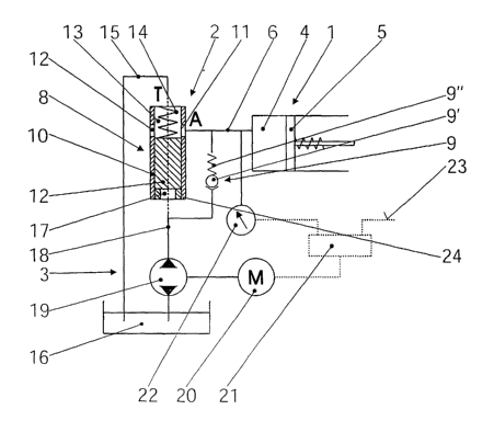
In Fig. l, by way of summary, a cylinder/piston
unit is identified with the designation 1, a valve unit
with 2, and an electric motor/pump unit with 3. Provided
inside the cylinder/piston unit 1 is a pressure chamber 4,
which communicates via a line 6 to the valve unit 2, in
conjunction with which the pressure fluid contained in the
pressure chamber 4 acts upon a piston 5. This piston 5 is
a part of a friction clutch (not shown here) or is
permanently and directly in communication with it. The
force exerted by the piston 5 against the force of a
AMENDED PAGE
CA 02504676 2005-05-02
spring (not shown here) acts upon the clutch plates in the
friction clutch. As the pressure increases, the torque
transmitted or exerted by the clutch also increases.
The valve unit 2 contains a dump valve 8 and a
nonreturn valve 9. The latter has a ball 9' that is
pressed against a seat by a spring 9 " . The dump valve 8
is formed by a sleeve 10 with at least one opening 11,
which opening communicates with the pressure chamber 4 via
the line 6, and by a piston 12 capable of being displaced
in the sleeve 10. The piston 12 separates a first chamber
13 containing a pressure spring 14 from a second chamber
17. The first chamber 13 communicates via an outflow line
15 with a sump 16, from which the electric motor/pump unit
3 sucks up fluid and into which it delivers fluid.
Connected to the second chamber 17 is a pressure line 18,
which for its part provides the communication between the
electric motor/pump unit 3 and - via the nonreturn valve 9
- the pressure chamber 4.
The electric motor/pump unit 3 consists of a pump
for the pressure fluid and a motor 20, which is actuated
by a controller 21. The latter, for its part, receives an
actual value determined by a pressure sensor 22 as an
input signal and a set point value via a line 23, which
values correspond in each case to the contact pressure or
to the torque transmitted or to be transmitted by the
A1~NDED PAGE
CA 02504676 2005-05-02
_ g _
clutch.
The function of the arrangement described here is
as follows: in the position represented in Fig. 1, the
electric motor/pump unit 3 delivers either not at all, or
at a pressure that is insufficient to cause the nonreturn
valve 9 to open or the dump valve 8 to close . No pressure
is present in the pressure chamber valve 4, and the clutch
(not shown here) is accordingly not subject to loading and
as such does not transmit any torque. If an increase now
takes place in the pressure of the pressure medium
supplied by the pump 19 in the line 18, this acts in the
second chamber 17 on the under side of the slide 12
executed as a piston against the force of the spring 14.
If this pressure exceeds a specific value, the slide 12
closes the opening 11 and thus the outlet from the
pressure chamber 4. The nonreturn valve 9 does not open
until the opening 11 is fully closed, and pressure fluid
is then able to flow into the pressure chamber and to
actuate the clutch accordingly.
If the pump 19 is now suddenly brought to a halt,
the pressure acting on the slide 12 decreases, and the
latter is forced out of the way by the spring 14, whereby
the openings 11 once again become free and the pressure
fluid is able to escape from the pressure chamber 4 into
the sump 16. If the electric motor/pump unit 3 is reversed
so that the direction of supply is also reversed, so that
AMENDED PAGE
CA 02504676 2005-05-02
- 10 -
the pump 19 feeds from the pressure line 18 into the sump
16, a partial vacuum will be produced under the slide 12
which will cause it to accelerate significantly as it
moves out of the way. The clutch will then be opened fully
and instantaneously as the motor 20 is reversed, for
example as is required in the case of an ABS braking
sequence.
If the pressure chamber is under pressure, and if
the electric motor/pump unit 3 is at a standstill, the
pressure will be retained for a time if the sealing is
effective. This means that, in the case of stationary
operation with the clutch engaged, the electric motor/pump
unit 3 only needs to maintain sufficient pressure for the
slide to remain closed. In this way, the delivery quantity
is almost zero, since any leakage takes place for the most
part in the interior of the pump. A considerable saving in
energy is achieved by this means.
The variant illustrated in FiQ. 2 differs from the
previous embodiment only in the sense that the spring 14
does not act against the pressure exerted by the pump, but
the spring 14' acts in the same direction as the pressure
exerted by the pump. Otherwise the valve unit is the same.
The pump must be reversed here in order for the outflow to
take place.
The embodiment in Fig. 3 differs from that
AMENDED PAGE
CA 02504676 2005-05-02
- 11 -
illustrated in Fig. 1 only in the sense that the nonreturn
valve is repositioned in the interior of the pump. The
sleeve 10 with the opening 11 remains unchanged, and
present inside it are the piston and the slide 32, in the
interior chamber 33 of which the nonreturn valve 29 is
incorporated. It consists of a ball 29' and a spring 29 " .
In addition the slide 32 has a second opening 34, which
comes into alignment with the first openings 11 from a
certain pressure of the pressure medium and a certain
position of the slide 32. As the pressure of the pressure
medium increases, the slide 32 is first caused to move
upwards until the first opening 11 is obstructed and the
pressure chamber 4 is closed; a further increase causes
the nonreturn valve 29 to open, and fluid finds its way
through the openings 11, 34 in the pressure chamber 4 that
have come into alignment in the meantime. This arrangement
provides for the pressure chamber to be closed first,
without particular matching of the springs, and only then
to be filled with pressure medium.
All in all, in the manner described here, a means
of controlling clutches in the drive train of a motor
vehicle is permitted, which combines together very short
response times, the accurate adjustment of a blocking
moment or a coupling moment to be transmitted, a low
energy requirement to maintain the set moment and inherent
safety (in the event of failure of the system, no torque
AMENDED PAGE
CA 02504676 2005-05-02
- 12 -
is transmitted), and all of this by means of a very simple
and inexpensive arrangement.
AMENDED PAGE