Note: Descriptions are shown in the official language in which they were submitted.
CA 02504749 2005-04-20
ELECTRIC WINCH
BACKGROUND
The present invention relates generally to methods and apparatus for lifting
and hoisting.
More particularly, the present invention relates to winches and more
specifically for winches used
to lift personnel.
In many working environments, personnel are required to perform certain
functions at
elevated locations where platforms or other working surfaces are not provided.
In these situations,
a winch, or other type of lifting appliance, is often used to lift and support
the worker while
performing the task. Among the working environments where winches are commonly
used for
handling personnel are offshore oil and gas platforms and vessels.
Most facilities have dedicated, specially designed winches that are used only
for handling
personnel. These winches are known as 'manrider' winches and are often
designed with higher
safety design factors as compared to standard utility winches. In certain
regions, such as both the
Norwegian and UK Sectors of the North Sea, manrider winches are subject to
stringent rules and
regulations as equipment used in handling personnel. Manrider winches, which
must safely
support a worker in an elevated working position, must also allow that worker
some freedom of
movement to perform the assigned task. It is often difficult to balance the
need for complete safety
and fall support with the need to allow the worker being supported some
freedom of movement.
Thus, there remains a need to develop methods and apparatus for winches
developed
within rules and regulations such as those used in the North Sea that govern
equipment for
handling personnel, which overcome some of the foregoing difficulties while
providing more
advantageous overall results.
CA 02504749 2005-04-20
SUMMARY OF THE PREFERRED EMBODIMENTS
The problems discussed above are addressed by apparatus and methods for
operating a
winch system comprising a wire spooled onto a drum rotatably mounted to a
shaft. A permanent
magnet is mounted to the drum such that, when an electric current is applied
to a coiled winding
mounted to the shaft, the drum rotates about the shaft. The winch comprises a
first braking
system that controls the rotation of the drum about the shaft by controlling
the application of the
electric current to the coiled winding. The winch also comprises a second
braking system that
mechanically engages the drum so as to prevent the rotation of the drum about
the shaft. The
winch is used in conjunction with a control system that facilitates the use of
the winch with
lifting and supporting personnel working in elevated environments.
The preferred embodiments include an electric winch utilizing a permanent
magnet
electric motor integrated into the wire rope spool. The permanent magnet
electric motor
provides resistor induced emergency braking and motor-controlled emergency
lowering if power is
lost. Because the speed and torque of the motor are easily and precisely
controllable, preferred
embodiments may include climbing and walking functions to safely support
worker movement
while maintaining safety. Some embodiments are configured for top of derrick
mounting, i.e.
reduced number of wire lines. Because the motor is integrated into the drum,
the total number of
parts required is reduced. The fully electrical winch requires no other power
sources, i.e. hydraulic
or pneumatic supplies.
Thus, the present invention comprises a combination of features and advantages
that
enable it to overcome various problems of prior devices. The various
characteristics described
above, as well as other features, will be readily apparent to those skilled in
the art upon reading
2
CA 02504749 2005-04-20
the following detailed description of the preferred embodiments of the
invention, and by
referring to the accompanying drawings.
BRIEF DESCRIPTION OF THE DRAWINGS
For a more detailed description of the preferred embodiment of the present
invention,
reference will now be made to the accompanying drawings, wherein:
Figure 1 is a schematic representation of a winch system constructed in
accordance with
embodiments of the invention;
Figure 2 is a cross-sectional view of the winch of Figure 1; and
Figure 3 is a layout view of a remote control unit of the system of Figure 1.
DETAILED DESCRIPTION OF THE PREFERRED EMBODIMENTS
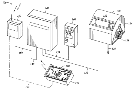
Refernng now to Figure 1, a schematic diagram illustrating the interconnection
of winch
system 10 is shown. Winch system 100 comprises winch 120, control panel 140,
local operator
station 160, base unit 180, and remote control 190. Winch 120 is an electric
motor operated
drum 122 mounted in frame 124. Wire 126 is reeled on drum 122 and extends from
the bottom
of frame 124. Mechanical braking system 128 is mounted to drum 122.
Control panel 140 is supplied by power cable 130 and includes the electronics
required to
operate winch 120. These electronics may include programmable logic
controllers with a control
system, a frequency drive, a power distribution system, resistors, and
electric relays and barners.
Control panel 140 supplies control signals and power to winch 120 along
connection 132.
Local operator station 160 is connected to control panel 140 via connection
134, which
transmits control signals for winch 120 to control panel 140. Local operator
station 140 may
include a full set of control switches including activators for emergency
functions such as stop and
lowering. Local operator station 160 is fixably mounted to the facility in a
desired location.
3
CA 02504749 2005-04-20
Several local operator stations 160 may be connected to a single control panel
140 and be equipped
with interlocks to prevent the use of more than one operator station at a
time. Similarly, one local
operator station 160 may selectively communicate with several control panels
140 to control a
selected winch 120.
Base unit 180 and remote control 190 operate together to provide remote,
mobile operation
of winch 120. Base unit 180 comprises a radio communication unit that can be
housed in a safe
area and is connected to and communicates with control panel 140 via
connection 182. Remote
control 190 includes operator controls 192 and a radio transmitter to transmit
signals 194 to base
unit 180. In some embodiments, remote control 190 may be connected to base
unit 180 by a cable.
A cross-sectional view of winch 120 is shown in Figure 2. Winch 120 includes
frame 124,
drum 122, and braking system 128. Winch 120 is preferably built for overhead
installation, with
wire running downwards in order to reduce wire wear and eliminate slack wire
and spooling
problems like backlash. Winch 120 is preferably built as an inside out
permanent magnet motor
where drum 122 rotates about shaft 206. The motor is frequency controlled,
giving full control
over motor speed and torque.
Drum 122 surrounds and is fixably attached to rotor 202 that includes
permanent magnets.
Rotor 202 is disposed about stator 204 that is fixably connected to shaft 206
and is formed from
coiled windings. Shaft 206 and stator 204 are stationarily connected to frame
124 such that when a
current is applied to stator 204, drum 122, supported by bearings 208, rotates
about shaft 206.
Drum 122 is preferably made with right hand winded grooves spooling of one
layer of 10 mm
wire. The speed of the drum is monitored by an external digital encoder.
Braking system 128 may include three different braking systems, namely an
electric motor
brake, an external fail safe brake, and a motor magnet brake. The electric
motor operates as an
4
CA 02504749 2005-06-20
electric motor brake by reducing the speed and torque of the rotor by reducing
the electrical current
supplied to the coiled windings. The speed and torque can be monitored by the
control system, and
the motor speed controlled to reduce and stop the drum according to the
operator signals. An
external fail safe brake 210 is energized and disengages when the winch is
started. Brake 210
controls pinion 212 that engages gear 214 that is connected to drum 122. Brake
210 will stay
disengaged until winch 120 is turned off or an emergency switch is pressed.
Brake 210 will also
engage in .case of power failure and can be manually disengaged by actuating
lever 216. In case of
power failure to the motor and a failure of brake 210, the motor will start
acting as a dynamo. In
this mode drum 122 will rotate and pay out wire a constant slow rate according
to the loading in
the wire. High speed emergency lowering will be impossible.
Winch 120 may also be equipped with an arrangement for manual release of the
brake.
This manual release may be actuated directly at winch 120 or actuated from
drill floor via a
pneumatic system. A manual pneumatic valve on the drill floor supplies air to
a pneumatic
cylinder on the winch activating brake lever 216. When the air is shut off,
the brake is applied.
The winch speed will still be limited by the resistor arrangement.
To ensure correct wire spooling, winch 120 is preferably made for only one
layer of wire
on drum l :?2. In addition to this, the drum is fitted with grooves 21$. The
wire is guided onto the
drum using spooling device 220 that directs the wire into the grooves.
The power system that operates winch 120 may also comprise a frequency
converter
including braking chopper for running the winch motor clockwise and
counterclockwise. A
braking resistor may be used for dissipating regenerated energy when braking
with the electrical
motor. A contactor/resistor arrangement may be supplied to short circuit the
motor windings for
braking in case of loss of frequency converter and for protection against
motor over-voltage. The
5
CA 02504749 2005-06-20
winch control system can be equipped with a separate potential free contactor
that can be
connected to other drill floor machines emergency shut down circuits,
disabling other connected
machinery when the winch is in operation. On drilling rigs with advanced
drilling control and
monitoring system, the winch can easily be incorporated into the rig's anti
collision system. The
winch may also be fitted with a heave compensating system, making it possible
to work on fixed
well equipment on a floating vessel.
One embodiment of remote control 190 is shown in Figure 3. Remote control 190
includes
on/off switch 300, joystick 302, start/stop switch 304, walk button 306, climb
button 308, display
310, display controls 312 and 314, warning lights 316 and 318, and emergency
stop button 320.
Once remote control 190 is activated by on/off switch 300, pushing the
startJstop switch 304 will
send a pulse signal to control panel 140 to initiate a start sequence during
which, the motor will be
powered up, the brake resistor arrangement disabled and the brake released.
Pushing the start/stop
switch 204 again will initiate a stop sequence during which, motor speed is
set to zero, the
mechanical brake is applied, and the brake resistor arrangement is enabled.
When the shut down
sequence is confirmed, the motor is powered down.
To operate the winch upwards or downwards, joystick 302 is utilized. Joystick
302 is
preferably fitted with a dead man's grip, i.e. a separate activation switch in
the joystick handle. The
activation switch must be pressed with joystick 202 in the zero position in
order to start operations.
If the activation switch is released during operation with joystick 202 out of
the zero position, the
winch will continue running but a new start from the zero position requires
depressing of the
activation switch. When receiving the hoist signal from joystick 202, the
frequency converter will
change the motor speed according to joystick position. The maximum hoisting
speed and
acceleration is limited by the control system.
6
CA 02504749 2005-06-20
When lowering the load in normal operation, the frequency converter/braking
chopper will
' measure the DC-bus voltage and start operating (dissipating regenerated
energy in the braking
resistor) when exceeding the preset limit. Max tension in the wire will be
controlled by the
frequency converter. In case of excessive external force, the tension will not
exceed a
programmable hard-coded value. The winch will be equipped with a sensor for
upper and lower
position stops such that a signal from this sensor will cause the winch to
stop at downwards
position independently of other control signals. The joystick can be operated
in "left" position, in
this position the v~~inch is in creep speed mode, giving maximum 10% of normal
speed.
Winch 120 may be equipped with a climb function 308 that can be selected /
deselected at
the remote control panel. When selected, the rider can adjust his position by
applying additional
force in downwards or relieving tension in an upward direction. Maximum speed
limits in both
directions are 0.1 Sm/s when this function is activated. The operator can at
all time take control of
the movement by using the joystick, which deactivates the climb function.
Winch 120 may also be equipped with a walk function 306 that can be selected /
deselected
at the remote control panel. When activated, winch 120 will keep a constant
low tension in the
wire, preventing a slack wire situation. The rider can move around with a
small pull in the wire.
The function can only be activated when the load is below 15% of max load. In
case of a person
falling from an elevated position with this function activated, the person
will be lowered with a
preset speed of O.lSm/s. The operator can at all time take control of the
operation of the winch,
either by activating the joystick, which deactivates the walk function.
When the control system detects "slack wire", a red indicator lamp 216 will
illuminate on
the console. The slack wire function will stop downwards movement if the wire
tension drops
below 2% of max tension.
7
CA 02504749 2005-06-20
Referring back to Figure 1, winch 120 is equipped with three emergency stops
located at
remote control console 190, at local operator station 160 and at winch 120.
These are hard wired
emergency stop buttons 220 (see Figure 3) that will engage the mechanical
brake, engage the
magnetic brake and disconnect power from the motor. Pressing the emergency
stop switch 220
will immediately stop winch 120 and apply the parking brake. The power to the
motor will also be
shut down but control system 140 will still be monitoring winch 120. Any
detection of internal
failures, including overspeed, overpull, power problems, and communication
problems, will also
produce an emergency shutdown.
To be able to lower the load in case of equipment failure or loss of power,
winch 120 is
equipped with an emergency lowering circuit. This arrangement will lower the
load in a controlled
manner in case of loss of power from the frequency converter. If the
mechanical brake is engaged
and the PLC/remote control is working, the brake can be released by operating
an emergency
release switch at local operator station 160. The control power to the
emergency brake release
circuit comes from the rig UPS system. A diode bridge will allow for dual
brake release signal,
1 S both for the PLC (in normal operation) and for the emergency lowering
circuit. Overspeed
detection will still be operating, and if overspeed is detected, the brake
will engage.
In case of failure in the PLC/remote control system, but with UPS power
available, the load
can be lowered by activating the emergency lowering switch at local operator
station 160. In case
of no UPS power available, the mechanical brake can be disengaged manually by
a hand operated
lever 216 see Figure 2) on the brake. In this mode, the winch speed will still
be limited by the
resistor an-angement and all control system safety features are disabled.
Emergency lowering
speed is always limited by the motor braking resistance (dynamo effect) and
the load being
8
CA 02504749 2005-06-20
lowered. Free fall will never be possible except for wire breakage or complete
mechanical failure
of the winch.
Winch 120 can also be equipped with an arrangement for manual release of the
brake from
drill floor. A manual pneumatic valve on the drill floor can supply air to a
pneumatic cylinder on
the winch activating brake lever 216 (see Figure 2). When the air is shut off,
the brake is applied.
The winch speed will still be limited by the resistor arrangement. An
emergency hoisting feature
can also be; included, wherein a crank handle can be inserted onto the drum,
and the winch wire
may be manually spooled in at a gear ratio of 1:8.
At loss of main power to the frequency converter, the mechanical brake will
engage and the
contactor/emergency lowering resistor arrangement will make sure that the
motor does not
generate overvoltage at the motor terminals. In case of loss of power to the
PLC, the mechanical
brake will engage and the contactor/emergency lowering resistor arrangement
will make sure that
the motor does not generate overvoltage at the motor terminals.
PL(: failure will cause the mechanical brake to engage and the emergency
lowering
contactor will short-circuit the motor windings over the emergency lowering
resistor arrangement.
If the PLC detects a failure in remote control system 190, winch 120 will be
shut down in a
safe sequence. All special functions will be shut off. Speed will be set to
zero, and the mechanical
brake will lie applied. Remote control failure will cause the mechanical brake
to engage and the
emergency lowering contactor will short-circuit the motor windings over the
emergency lowering
resistor arrangement. Failure on the remote control system 190 will not affect
operation from local
operator station 160, which always can be activated.
9
CA 02504749 2005-06-20
Frequency converter failure will cause the mechanical brake to engage and the
contactor/emergency lowering resistor arrangement will make sure that the
motor does not
generate overvoltage at the motor terminals.
At .all times, the PLC will monitor and regulate the speed of the winch drum
by use of two
independent sensors. In case of speed exceeding the preset limit, the PLC will
engage the
mechanical brake. The detection has the same priority in the emergency stop
loop as the
emergency stop push button.
At all times, the PLC will monitor the wire tension through the motor torque.
In case of
tension exceeding the preset limit, the winch will pay out wire unless the
speed exceeds the
overspeed limit. As a backup torque measurement, the input current to the
frequency converter is
monitored. If the current exceeds a preset limit, the winch will be stopped
and shut down.
The. PLC may be equipped with a system monitoring and diagnosing software.
This
software rruonitors the PLC, frequency converter and remote radio control
status, and also the
communication links and instrumentation on the winch. Any fault detected will
generate an alarm.
1 S Alarms generate a message that will be displayed on the LCD-screen 310 on
the remote radio
console 190 (see Figure 3).
The remote radio console 190 may be equipped with a system monitoring and
diagnosing
software. lntemal errors related to the remote radio console 190 will be
displayed on the LCD-
screen 310 on the console. The frequency converter is equipped with a system
monitoring and
diagnosing software. Internal errors related to the frequency converter will
be displayed on an
LCD-screen on the frequency converter.
The unique features of this winch are derived from the electrical motor that
is used. This is
a slow rotating permanent magnet motor integrated into the drum that provides
very good torque
".,
CA 02504749 2005-06-20
control, which can be used for various new functions. Also, this motor will
produce torque even at
loss of power, so normal free falling is impossible.
While preferred embodiments of this invention have been shown and described,
modifications thereof can be made by one skilled in the art without departing
from the scope or
teaching of this invention. The embodiments described herein are exemplary
only and are not
limiting. Many variations and modifications of the system and apparatus are
possible and are
within the scope of the invention. For example, the relative dimensions of
various parts, the
materials from which the various parts are made, and other parameters can be
varied, so long as
the winch apparatus retain the advantages discussed herein. Accordingly, the
scope of protection
is not limited to the embodiments described herein, but is only limited by the
claims that follow,
the scope ~of which shall include all equivalents of the subject matter of the
claims.
11