Note: Descriptions are shown in the official language in which they were submitted.
CA 02504775 2005-05-03
WO 2004/042184 PCT/AU2003/001485
-1 -
AN IMPROVED ROTARY ROLLER REAMER
Field of the Invention
The present invention relates to an improved rotary roller reamer and to
improvements to the various components thereof.
Background of the Invention
During drilling operations, the drill bit is subject to wear and thus the
dimension
of the drill hole will vary over time. To ensure that the dimension of the
drill hole
is held true, rotary roller reamers are located in the drill string and are
used to
ream out the drill hole to the required dimension. The inclusion of rotary
roller
reamers in the drill string enables the drill bit to be used for a longer
period
without changeover and this prevents considerable costly downtime.
The working environment of rotary roller reamers is very harsh. Consequently,
the components of the roller reamer frequently need servicing, repair or
replacement. As downtime for repairs is very costly, it is advantageous to
extend the working life of such roller reamers and to thereby reduce down time
due to repairs. It is also advantageous for the rolller assemblies used in
rotary
roller reamers to be quickly and easily removed and replaced from their
respective pockets in the reamer body.
The present invention seeks to provide an improved rotary roller reamer and
various components thereof.
The present invention also seeks to provide a pressure equalisation means for
a device.
CA 02504775 2005-05-03
WO 2004/042184 PCT/AU2003/001485
-2-
Summary of the Invention
According to a first aspect of the present invention there is provided a
rotary
roller reamer including a reamer body having at least one pocket for receiving
a
roller assembly and wherein said roller assembly includes a plurality of
components which are connected together to form a single cartridge which can
be inserted into said pocket.
Preferably, said cartridge is secured in said pocket by means of a single
fastener device.
According to a second aspect of the invention there is provided a roller
assembly for a rotary roller reamer, said roller assembly including a roller
pin
and a crushing roller arranged to be mounted on said roller pin and to rotate
thereabout, and wherein the roller assembly.is connected together so as to
form
a single cartridge which can be inserted into a pocket of the rotary roller
reamer.
Preferably, the cartridge is arranged to be secured to the pocket by means of
a
single fastener device.
Preferably, said roller assembly further includes a first retaining means for
retaining said roller pin within said pocket, said first retaining means
including a
first plug which is arranged to be connected to the roller pin so that the
roller
pin, crushing roller and first plug form said single cartridge which can be
inserted into the pocket of the rotary roller reamer.
Preferably, the first plug has a first surface against which a first end of
the roller
pin mates and a second surface arranged to engage with a sidewall of said
pocket, said sidewall of said pocket and said second surface of said first
plug
being configured so that the first plug is drawn into the pocket when said
fastener device is used to secure the roller assembly to said pocket.
Preferably, the roller assembly further includes a second retaining means.
CA 02504775 2005-05-03
WO 2004/042184 PCT/AU2003/001485
-3-
Preferably, a first thrust ring is provided between the roller pin and a first
end of
the crushing roller and a second thrust ring is provided between a second end
of the crushing roller and said second retaining means. The first and second
thrust rings are preferably sacrificial thrust rings arranged to accommodate
thrust loads applied to the crushing roller during use of the rotary roller
reamer.
Preferably, the first surface of the first plug is complimentary to the first
end of °
the roller pin. The first end of the roller pin is preferably formed with an
enlarged head.
The roller pin preferably includes a shank having central longitudinal blind
bore
formed therein that opens through a second end of the roller pin. The bore
forms a lubricant reservoir. The bore opens into a side port that extends
substantially perpendicular thereto and opens into a primary lubricant
distribution groove. The primary lubricant distribution groove preferably
extends
substantially longitudinally of the roller pin and may adopt various
configurations, for example, a "figure 8" configuration.
Lubricant can be supplied from the reservoir, through the side port and into
the
primary lubricant distribution groove during rotation of the crushing roller
about
the roller pin. The lubricant is distributed over the shank of the roller pin
as the
crushing roller rotates thereabout.
Seal means are preferably provided between the crushing roller and the shank
of the roller pin to prevent escape of lubricant.
Preferably, pressure equalisation means is provided in the bore of the roller
pin.
The pressure equalisation means is arranged to equalize the pressure between
the drilling mud surrounding the body of the rotary roller reamer and the
lubricant contained in the bore of the roller pin. The pressure equalisation
means may include a filter, such as a sintered metal filter.
CA 02504775 2005-05-03
WO 2004/042184 PCT/AU2003/001485
-4-
In a preferred embodiment, the first plug is formed as a frustum having a base
and a top. The frustum preferably has an angle of less than or equal to
7° to its
central longitudinal axis. Preferably, this angle is approximately 3°.
The base
of the first plug is arranged to be positioned uppermost in the pocket. The
base
has an outer diameter which is smaller than the outer diameter of the top.
The base of the first plug has an underside that is preferably shaped to
engage
with a mating portion of the pocket. The mating portion of the pocket
preferably
includes a post that includes a central threaded bore that is arranged to
enable
the fastener to be screwed there into.
The first plug preferably includes a fastener-receiving cavity that opens
through
a sidewall of the first plug and also into the base of the first plug. The
cavity is
configured so that the fastener can be passed through the opening in the
sidewall and located there within. In this position, the leading end of the
fastener extends through the opening in the base. In this manner, the leading
end of the fastener can be screwed into the threaded bore formed in the post
of
the pocket.
The first plug preferably also includes an elongate screw connector slot
formed
in the sidewall thereof. The screw connector slot being configured to receive
the head of a screw connected to the enlarged head of the roller pin.
An aperture is preferably formed in the top of the first plug and is arranged
so
that a tool can be passed there through to enable the fastener to be screwed
into the bore of the post.
In a particularly preferred form, the fastener is a socket head fastener and
the
socket head is arranged to be located within an upper portion of the fastener-
3o receiving cavity. The upper portion of the cavity is configured so that
when the
fastener is screwed into the post of the pocket, the first plug is drawn into
the
pocket, and when the fastener is unscrewed, the first plug is lifted out of
the
pocket.
CA 02504775 2005-05-03
WO 2004/042184 PCT/AU2003/001485
-5-
The second retaining means preferably includes a second plug which is formed
as a frustum. The frustum preferably has an angle of less than or equal to
7°- to
its central longitudinal axis. Preferably, the angle is approximately
3°-. The
second plug has a base, a top and a side wall. The base has a larger outer
diameter than the top and is arranged to be positioned lowermost within the
pocket.
A bore is formed in the second plug substantially perpendicular to the central
longitudinal axis of the second plug. The bore is arranged to receive the
second end of the roller pin. Preferably, the bore is sized for a sliding fit
with
the second end of the roller pin.
A minor bore is also preferably provided in the sidewall of the second plug.
The
minor bore is arranged to aid pressure equalization between the lubricant
contained in the lubricant reservoir and the mud surrounding the roller
assembly
during use thereof.
Extending from the side wall of the second plug is a lug. The lug is arranged
to
2o engage with a complimentary shaped recess formed in a portion of the
pocket.
In accordance with a preferred embodiment of the invention, each pocket of the
rotary roller reamer includes a lower tapered socket, a primary cavity, a
secondary cavity and an upper tapered socket. The upper tapered socket is
preferably located at the up hole end of the rotary roller reamer and the
lower
tapered socket is preferably located at the down hole end of the rotary roller
reamer.
The upper tapered socket is arranged to receive the first retaining means. The
upper tapered socket includes a semi-circular truncated conical seat of less
than or equal to 7°- angle to a normal axis of the socket (i.e. the
axis normal to
the longitudinal axis of the rotary roller reamer). Preferably, the angle is
approximately 3°-. The socket is tapered so that the smaller diameter
of the
CA 02504775 2005-05-03
WO 2004/042184 PCT/AU2003/001485
-6-
socket forms part of the floor of the pocket. Tangential to the conical seat
is an
entrance guide-way having sides matching the taper of the conical seat. The
seat extends for approximately 270°- arc length, with the remainder of
the arc
length opening into the secondary cavity. Preferably, the seat extends for
greater than 180°- arc length.
Located substantially centrally of the upper tapered socket is the post in
which
the fastener of the first plug is preferably arranged to be secured.
The primary cavity (or roller cavity) is preferably configured to provide
operating
clearance for the crushing roller mounted on the roller pin. The primary
cavity is
necked down as compared to the external diameter of the reamer body. This
results in the primary cavity having a depth in the direction normal to the
longitudinal axis of the reamer body which is less than the depth of the upper
and lower tapered sockets.
The secondary cavity is preferably formed as a flanked trapezium shape which
narrows at the floor of the cavity. The secondary cavity forms a seat for the
head of the roller pin.
The lower tapered socket is preferably arranged to receive the second
retaining
means. The lower tapered socket includes a semi-circular truncated conical
seat of less than or equal to 7°- angle to a normal axis of the socket
(i.e. the axis
normal to the longitudinal axis of the rotary roller reamer). Preferably, the
angle
is approximately 3°-. The socket is tapered so that the larger diameter
of the
socket forms part of the floor of the pocket.
Located in the sidewall portion of the lower tapered socket is a groove or
ledge
arranged to receive the security lug of the second plug. The groove or ledge
is
preferably substantially crescent shaped.
According to a third aspect of the invention there is provided a crushing
roller for
a rotary roller reamer, said crushing roller including a central portion and
first
CA 02504775 2005-05-03
WO 2004/042184 PCT/AU2003/001485
_7_
and second end portions, the central portion having an external diameter
greater than the external diameter of the first and second portions, and
wherein
the central, first and second portions are studded with projection means.
The projection means are preferably arranged on the central portion so that a
contact area of the projection means with a portion of a wall of a drill hole
being
reamed overlaps. The projection means may be arranged on at least. one helix
about the central portion of the crushing roller. The helix may advantageously
be a left hand helix. Such an arrangement serves to reduce the thrust loading
in the vertical plane during use of the crushing roller.
Preferably, each projection means includes a button mounted in a hole formed
in the crushing roller. The button is preferably a domed shaped tungsten
carbide button.
In accordance with one preferred form, the buttons on the central portion are
arranged in four rows of eight and are set on a left-hand 3.31699" pitch
helix.
Each row is separated by 90°- of angular rotation and the starting
point for each
row commences in a progressive step equal to 0.125 x 1/9t" of the helical
datum
curve length. Each projection means is spaced at 1/9t" of the helical curve
length.
Preferably, located between each of the helically spaced rows are flutes which
are generated on the same helical datum path as the projection means. The
flutes are arranged to provide an increased mud flow past the roller and
increase the clearance through which the residue from the reamer can pass.
According to a fourth aspect of the present invention there is provided a
rotary
roller reamer including a reamer body having at least one pocket for receiving
a
roller assembly, said roller assembly including a pin and a crushing roller
arranged to be mounted on said pin, seal means between the pin and the
crushing roller and means for retaining said pin within said pocket, and
wherein
the pin includes a bore having pressure equalisation means located there
CA 02504775 2005-05-03
WO 2004/042184 PCT/AU2003/001485
_$_
within, the pressure equalisation means serving to substantially equalize the
pressure on the seal means.
Preferably, the pressure equalisation means serves to equalise the pressure
between the drilling mud surrounding the body of the rotary roller reamer
during
use and a lubricant contained in the bore of the roller pin.
The crushing roller is preferably arranged to rotate about the roller pin.
The pressure equalisation means may include a filter, such as a sintered metal
filter.
According to a fifth aspect of the invention there is provided a rotary roller
reamer including a reamer body having at least one pocket for receiving a
roller
assembly, said roller assembly including a roller pin and a crushing roller
arranged to be mounted on said roller pin, wherein the reamer body has a
primary outer diameter in an area distal to the crushing roller and a
secondary
outer diameter in an area adjacent to the crushing roller, and wherein the
secondary outer diameter is reduced as compared to the primary outer diameter
so as to provide stress relief.
According to a sixth aspect of the invention there is provided a pressure
equalisation means for a device having at least one seal means for sealing a
supply of lubricant located between a first and a second member of said
device,
said pressure equalisation means being arranged to be mounted in said device
and arranged so that it acts to equalise the pressure applied by the lubricant
to
a first side of said at least one seal means with the pressure of a fluid
being
applied on a second side of the at least one seal means.
Brief Description of the Drawings
Embodiments of the invention will now be described, by way of example only,
with reference to the accompanying drawings in which:-
CA 02504775 2005-05-03
WO 2004/042184 PCT/AU2003/001485
_g_
Figure 1 is a cut-away view of a rotary roller reamer according to an
embodiment of the invention;
Figure 1 A is an enlarged view of the central portion (i.e, the pocket and the
roller assembly) of the rotary roller reamer shown in Figure 1;
Figure 2 is a partial assembly view of a roller assembly in accordance with an
embodiment of the invention adjacent to a reamer body having multiple pockets;
Figure 3 is a central longitudinal cross sectional view of the roller assembly
shown in Figure 2 mounted in a pocket of a rotary roller;
Figure 3A is a part cross sectional view of one end of the roller assembly
along
a line offset from the centre line of the rotary roller reamer;
Figure 4 is a longitudinal cross sectional view of the pocket of the rotary
roller
reamer shown in Figure 3;
2o Figures 5 to 8 are perspective views of a first retaining means in
accordance
with an embodiment of the invention;
Figures 9 to 11 are perspective views of a second retaining means in
accordance with an embodiment of the invention;
Figure 12 is a side view of a crushing roller in accordance with an embodiment
of the invention;
Figure 13 is a longitudinal cross sectional view of the crushing roller shown
in
Figure 12;
Figure 14 is an end view of the crushing roller shown in Figure 12;
CA 02504775 2005-05-03
WO 2004/042184 PCT/AU2003/001485
-10-
Figures 15 to 17 are views of a roller pin in accordance with an embodiment of
the invention;
Figure 18 is a cross sectional view showing connection of the first retaining
means to the connector screw which extends from the enlarged head of the
roller pin;
Figure 19 is cross sectional view showing insertion of the retaining plug in
the
connector screw slot of the first retaining means;
Figure 20 is a partial cross sectional view showing insertion of a roller
cartridge,
(i.e, the assembled roller assembly) into a pocket of the rotary reamer;
Figure 21 is a perspective view of the stabilization band shown in Figure 1A;
' 15
Figure 22 is a front view of the stabilization band shown in Figure 21; and
Figure 23 is a side view of the stabilization band shown in Figure 21.
Detailed Description of the Preferred Embodiments
Figures 1 and 1A illustrate a rotary roller reamer 10 in accordance with an
exemplary embodiment of the invention. The rotary roller reamer 10 has a male
end 12 and a female end 14. The rotary roller reamer 10 is arranged to be
attached to a drill string (not shown). As shown in this embodiment, the male
end 12 is located at the down hole end of the rotary roller reamer 10 and the
female end 14 is located at the up hole end of the rotary roller reamer 10. It
will
of course be appreciated that the configuration or nature of the respective
ends
of the rotary roller reamer 10 may vary.
The rotary roller reamer 10 includes a tubular reamer body 16 which includes
three circumferentially spaced pockets 18. Located within each pocket 18 is a
roller assembly or roller cartridge 20. The pockets 18 as illustrated are
equally
CA 02504775 2005-05-03
WO 2004/042184 PCT/AU2003/001485
-11 -
spaced about the periphery of the reamer body 16 and are located in a section
16a of the body 16 that has a larger outer diameter than the remainder of the
body 16. Although three pockets 18 are illustrated, it will be appreciated
that
arrangements with different numbers of pockets 18 and spacings are
envisaged.
Figure 2 better illustrates the pockets 18 formed in the reamer body 16. This
figure also illustrates the cut away sections or mud ways 17 formed between
adjacent pockets 18.
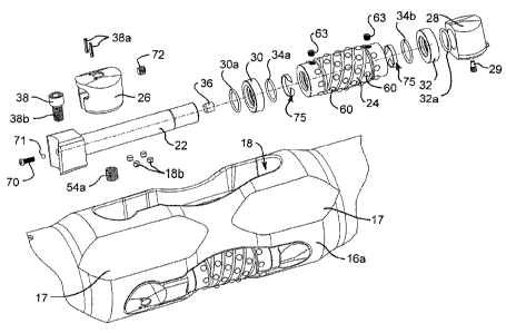
Figure 2 illustrates the roller assembly 20 in a disassembled condition. The
roller assembly 20 includes a roller pin 22, a crushing roller 24, a first
retaining
means 26, a second retaining means 28, a retaining screw 29, a first thrust
ring
30, a second thrust ring 32, a pair of seals 34a, 34b, a pressure equalisation
means 36, a fastener 38, a pair of self locking pins 38a, a connector screw 70
and a retaining plug 72.
When the components of the roller assembly 20 are assembled together they
form a single cartridge which can be secured, using the fastener 38, in the
pocket 18 of the rotary roller 10. During use, the crushing roller 24 is
arranged
to rotate about the roller pin 22 so that it can be used to ream the sidewalls
of
the drill hole through which the rotary roller reamer 10 is passed. The nature
of
each of the components of the roller assembly 20 and the pockets 18 formed in
the reamer body 16 will now be described in more detail.
Figures 3, 3A and 4 best illustrate the configuration of each of the pockets
18
and the engagement of the roller assembly 20 within its respective pocket 18.
Each pocket 18 includes a lower tapered socket 40, a primary cavity 42, a
secondary cavity 44 and an upper tapered socket 46. The lower tapered socket
40 is located at the down hole end of the rotary roller reamer 10, whilst the
upper tapered socket 46 is located at the up hole end of the rotary roller
reamer
10. The lower tapered socket 40 is arranged to receive the second retaining
means 28, whilst the upper tapered socket 46 is arranged to receive the first
CA 02504775 2005-05-03
WO 2004/042184 PCT/AU2003/001485
-12-
retaining means 26. The primary cavity 42 is arranged to receive the roller
pin
22 and the crushing roller 24 which is mounted thereon. The primary cavity 42
is sized and configured to provide operating clearance for the crushing roller
24
during use of the rotary roller reamer 10. The secondary cavity 44 forms a
seat
for the head 22a of the roller pin 22.
The lower tapered socket 40 includes a semi-circular truncated conical seat of
less than or equal to 7-°° angle to a normal axis of the socket
18 (i.e. the axis
normal to the longitudinal axis of the rotary roller reamer 10). As
illustrated, this
angle is approximately 3°-. The lower tapered socket 40 is tapered so
that the
larger diameter of the socket 40 forms part of the floor 18a of the pocket 18.
Tangential to the conical seat is an entrance guide way 40a having sides
matching the taper of the conical seat.
Formed in the lower part of the lower tapered socket 40 and coincident with
the
floor 18a of the pocket 18, is a semi-circular recess 40b. This recess 40b is
a
security recess which is arranged to receive a complimentary shaped lug 28k
formed on the second retaining means 28. The function of the security recess
40b and the lug 28k will be discussed in more detail subsequently.
Installed in a portion of the floor 18a of the lower tapered socket 40 so as
to be
positioned below the head 22a of the roller pin 22 are four carbide inserts
18b.
The carbide inserts 18b are provided to prevent wear of the floor 18a of the
pocket 18 due to movement of the head 22a during use of the rotary roller
reamer 10.
The primary cavity 42, as clearly illustrated in Figure 4, is necked down as
compared to the external diameter of the reamer body 16. Additionally, the
floor
18a of the primary cavity 42 steps downwardly in a direction towards the
centre
line of the reamer body 16. Thus, the primary cavity 42 has a depth in a
direction normal to the longitudinal axis that is sufficient to provide
working
clearance for the crushing roller 24. Additionally, the external diameter of
the
reamer body 16 in this area is reduced or "necked down" as compared to the
CA 02504775 2005-05-03
WO 2004/042184 PCT/AU2003/001485
- 13-
external diameter of the reamer body 16 iri the areas adjacent to the lower
and
upper tapered sockets 40, 46. This necked down configuration of the reamer
body 16 provides stress relief in.the area of the pockets 18.
The secondary cavity 44 is formed with a flanked trapezium shape which
narrows at the down hole end of the cavity 44.
The upper tapered socket 46 includes a semi-circular truncated conical seat of
less than or equal to 7°- angle to the normal axis of socket 46. As
illustrated,
this angle is approximately 3°-. The upper socket 46 is tapered so that
the
smaller diameter of the socket 46 forms part of the floor 18a of the pocket
18.
The seat extends for approximately 270°- arc length, with the remainder
of the
arc length opening into the secondary cavity 44. Located substantially
centrally
of the upper tapered socket 46 is a post 52. The post 52 includes a bore 54
which is threaded so that it can receive the fastener 38. Alternatively, as
illustrated, a threaded insert 54a may be located in the bore 54.
Figures 5 to 8 illustrate the first retaining means 26. The first retaining
means
26 is formed as a first plug 26 and is arranged to be received within the
upper
tapered socket 46. The first plug 26 is formed as a frustum. The frustum has
an angle of less than or equal to 7°- to its central longitudinal axis
and includes a
base 26a and a top 26b. As illustrated, the frustum has an angle of
approximately 3-°°. The base 26a is arranged to be positioned
lowermost in the
lower tapered socket 46. The base 26a has an outer diameter which is smaller
than the outer diameter of the top 26b. The underside of the base 26a is
shaped to engage with the floor 18a of the pocket 18 in the area of the upper
tapered socket 46. In particular, the base 26a is shaped so that it will mate
with
the post 52.
3o The first plug 26 includes a fastener-receiving cavity 26c that opens
through a
sidewall 26d and also into the base 26a of the first plug. The cavity 26c is
configured so that the fastener 38 can be positioned within and so that the
leading end 38b of the fastener 38 can be secured within the bore 54 formed in
CA 02504775 2005-05-03
WO 2004/042184 PCT/AU2003/001485
-14-
the post 52. An aperture 26e is located in the top 26b of the first plug 26
and is
configured so that the working end of a tool can be passed there through. This
enables the fastener 38 to be screwed into and out of the bore 54 of the post
52.
Formed in the top 26a of the first plug 26 is a pair of bores arranged to
receive
the self locking pins 38a. The self locking pins 38a are configured to
properly
locate and lock the fastener 38 within the fastener-receiving cavity 26c.
The sidewall 26d of the first plug 26 also includes an elongate connector
screw
slot 26f which enables the first plug 26 to be connected to a connector screw
70
which extends from the enlarged head 22a of the roller pin 22. The connector
screw slot 26f includes a threaded upper portion 26f' which is arranged to
receive a threaded retaining plug 72 (Figure 19). Prior to receiving the
retaining
plug 72, the threaded upper portion 26f' is sized to enable the head 70a of
the
connector screw 70 to pass there through. In this manner, the head 70a of the
,
connector screw 70 can be inserted into the connector screw slot 26f and then
the shank of.the screw 70 can be moved along the length of the slot 26f. The
connection between the screw 70 and the first plug 26 will be described in
more
detail subsequently.
As best illustrated in Figure 3, the fastener 38 is a socket head fastener.
The
head of the fastener 38 is arranged to be located within an upper portion of
the
cavity 26c so that when the fastener 38 is screwed into the post 52, the first
retaining means 26 is drawn into the lower tapered socket 46 and when the
fastener 38 is unscrewed, the first retaining means 26 is lifted out of the
upper
tapered socket 46. The configuration of the sidewalls of the lower tapered
socket 46 and the shape of the head 22a of the roller pin 22 facilitate this
action
of the first retaining means 26. As the first retaining means 26 (first plug
26) is
3o connected to the roller pin 22, movement of the first plug 26 in and out of
the
upper tapered pocket 46 will result in movement of the entire roller cartridge
20
in and out of the pocket 18.
CA 02504775 2005-05-03
WO 2004/042184 PCT/AU2003/001485
-15-
Figures 9 to 11 illustrate the second retaining means 28. The second retaining
means 28, or second plug, is formed as a frustum. The frustum has an angle of
. .less than or equal to 7°- to its central longitudinal axis. As
illustrated, this angle
is approximately 3°-. The second plug 28 has a base 28b,' a top 28c and
a
sidewall 28d. The base 28b has a larger external diameter than the top 28c and
is arranged for positioning lowermost within the upper tapered socket 40. A
bore 28e is formed in a flat portion of the sidewall 28d of the second plug
28.
The bore 28e extends substantially perpendicular to the central longitudinal
axis
thereof. The bore 28e is arranged to receive a second end 22b of the roller
pin
22. The bore 28e is sized for a sliding fit with the second end 22b of the
roller
pin 22.
A threaded aperture 28f is formed in the base 28b of the second plug 28. The
threaded aperture 28f is arranged to receive a retaining screw 29 which
locates
the second end 22b of the roller pin 22 within the second plug 28. The
engagement of the retaining screw 29 with the roller pin 22 will be described
in
more detail subsequently.
Formed in the sidewall 28d of the second plug 28 is a minor bore 28j. The
function of the minor bore 28j will be explained subsequently.
As mentioned previously, the second plug 28 has a lug 28k formed on the lower
part thereof. The tug 28k is arranged to engage within the security recess 40b
formed in the lower tapered socket 40. This engagement serves to better retain
the roller assembly 20 within the pocket 18.
Figures 12 to 14 illustrate the crushing roller 24. The crushing roller 24 is
formed as a hollow cylindrical member having a central bore which is sized to
receive the shank of the roller pin 22. The crushing roller 24 has reduced
3o diameter portions at each end for primary engagement of the crushing roller
24
with the walls of the well bore. A secondary engagement diameter is formed
therebetween and is studded with a plurality of buttons 60 (not shown in
Figures
12 to 14). The buttons 60 are preferably domed shaped tungsten carbide
CA 02504775 2005-05-03
WO 2004/042184 PCT/AU2003/001485
-16-
buttons that are each mounted within an aperture 62. The carbide buttons 60,
in accordance with a preferred embodiment, are arranged in four rows of eight
and are set on a left-hand 3.31699" pitch helix. Each row is separated by
90°- of
angular rotation and the starting point for each row commences in a
progressive
step equal to 0.125 x 1/9t" of the helical, datum curve length. Each button 60
is
spaced at 1/9t" of the helical curve length.
It will be appreciated by those skilled in the art that the above arrangement
of
buttons 60 on the crushing roller 24 provides a very efficient use of the
carbide
buttons and thus significantly less carbide is used. This reduction in carbide
use is also expected to reduce the torque loading in the drill string. It will
further
be appreciated that other arrangements of the carbide buttons on the crushing
roller are envisaged. Advantageously, the carbide buttons are arranged so that
during use they provide substantially complete coverage of the portion of the
wall of the well or drill hole being reamed. In other words, the contact area
of
the various carbide buttons with the portion of the drill hole being reamed
overlaps.
Located between each of helically spaced rows of buttons 60 are flutes 64.
2o There are four flutes 64 and they are generated on the same helical datum
path
as the apertures 62. The flutes 64 are arranged to enable increased mud flow
past the crushing roller 24 and to increase the clearance through which the
crushing residue from the rotary roller reamer 10 can pass.
The inclusion of primary engagement diameters at the respective ends 24a, 24b
of the crushing roller 24 enables the rotary roller reamer 10 to be bi-
directional
(i.e. either up hole or down hole in its application). Seven holes 62a are
located
in each primary diameter for the insertion of further domed tungsten carbide
buttons 60a. The holes 62a are equally spaced and circumferentially drilled on
the surfaces normal to the roller central axis.
As illustrated in Figure 12, a further hole 62b drilled through to the central
bore
is formed in each of the primary engagement diameters. Each hole 62b is
CA 02504775 2005-05-03
WO 2004/042184 PCT/AU2003/001485
-17-
tapped with a female thread and is arranged to receive a pressure plug 63.
Each hole 62b has the dual function of a grease injection port and a purge
port.
The use of the pressure plugs 63 will be described in more detail
subsequently.
As illustrated in Figure 13, a pair of seal retention grooves 66 is formed
within
the wall of the central bore of the crushing roller 24 and are arranged to
receive
respective seals .34a, 34b. As shown, the seals 34a, 34b are simple o-rings.
However, the use of other types of seals is envisaged.
Also shown in Figure 13 are further annular grooves 24c intermediate the ends
of the bore of the crushing roller 24. Each groove 24c is arranged to receive
a
stabilizing band 75. As best illustrated in Figure 21, each stabilization band
75
is a band which is broken at point A to provide a gap between the respective
ends 75a, 75b of the band. The ends 75a, 75b terminate at an angle of about
45° (See Figure 23). Termination at other angles is envisaged.
Each stabilization band 75 is sized to provide a minimal running fit about the
shank of the roller pin 22 and to float within its respective groove 24c.
Thus, the
stabilization band 75 may either be rotatable with the roller pin 22 or with
the
crushing roller 24.
Such a stabilizing band 75 is preferably made of a material that is reasonably
hard and has a relatively low coefficient of friction. This material may be a
fluroropolymer selected from the range of polytetrafluorethylenes (PTFE)
marketed by DuPont under the TEFLON~ trade mark. However, more
preferably, such a material will be strengthened by the addition of a filler,
such
as with a glass, bronze or nickel filler. Ideally, the material will be a
bronze filled
PTFE.
3o In this form, the stabilizing band 75 tends to assist in maintaining the
rotation of
the roller pin 22 substantially stable about its longitudinal axis and along
its
entire length. In this respect, in some situations, a seals 34a, 34b may be
somewhat sensitive to end-to-end bounce of the roller pin 22, such as would
CA 02504775 2005-05-03
WO 2004/042184 PCT/AU2003/001485
-18-
normally be expected due to the reasonably severe impact compression
encountered by the roller assembly 20 during operation. The additional use of
a
stabilizing band 75 of this general type will thus assist with the smooth
operation
of the roller assembly 20.
Figures 15 to 18 illustrate the roller pin 22. The roller pin 22 includes a
central
longitudinal bore 22c (best shown in Figures 3 and 15) that opens through the
lower end 22b. The bore 22c in the shank of the roller pin 22 forms a
lubricant
reservoir. A side port 22d extends between the lubricant reservoir 22c and a
primary lubricant distribution groove 22e. The primary lubricant distribution
groove 22e extends longitudinally of the roller pin 22. As best shown in
Figures
16 and 17, the primary lubricant distribution groove 22e is formed in a
"figure 8"
configuration.
It will be appreciated that the lubricant reservoir 22c enables a lubricant to
be
stored in the roller pin 22 and subsequently supplied, via the side port 22d,
to
the distribution groove 22e during rotation of the crushing roller 24 about
the
roller pin 22. The lubricant is distributed over the shank of the roller pin
22 as
the crushing roller 24 rotates thereabout. The seals 34a, 34b retain the
lubricant on the shank of the roller pin 22.
A second side port 22i is located adjacent the second end 22b of the roller
pin
22 and intersects with the lubricant reservoir 22c. The side port 22i opens
into
a groove 22j. The function of the groove 22j and the side port 22i will be
described below.
Also formed adjacent the second end 22b of the roller pin 22 is a transverse
retaining slot 22g. The retaining slot 22g is arranged so that the leading end
of
the retaining screw 29 in the second retaining means 28 can be located in the
retaining slot 22g. In this manner, the roller pin 22 can be oriented relative
to
the second retaining means 28. The use of a retaining slot 22g enables limited
rotation of the roller pin 22 after connection to the second plug 28.
CA 02504775 2005-05-03
WO 2004/042184 PCT/AU2003/001485
-19-
As best shown in Figures 3 and 20, the pressure equalization means 36 is
positioned against a counter bore formed in the lubricant reservoir 22c. When
the roller cartridge 20 is located in the pocket 18, the portion of the
lubricant
reservoir 22c to the right side (as shown in Figure 3) of the pressure
equalization means 36 opens into the bore 28e of the second plug 28. The
second side port 22i of the roller pin 22 opens into the groove 22j (Figure
20)
which inturn aligns with the minor bore 28j formed in the second plug 28. The
minor bore 28j of the second plug 28 opens to the area surrounding the
crushing roller 24. Thus, it will be appreciated that there is a pressure flow
path
1 o from the area surrounding the crushing roller 24 to pressure equalization
means
36.
The pressure equalization means 36 acts to ensure that the pressure of the
lubricant within the bearing cavity (i.e. the clearance between the roller pin
22
and the crushing roller 24) is substantially equal to the pressure of the
drilling
mud which completely envelopes the rotary roller reamer 10 during a reaming
operation. It is important to equalize this pressure so as to prevent the
seals
34a, 34b from blowing in or out.
2o The pressure equalization means may take. the form of a filter 36. In one
embodiment, the filter 36 may be a sintered metal filter. The sintered metal
filter
may have an alloy composition of 68% copper, 27% nickel and 5% tin and a
micron capture equal to or about 30 Vim. The pressure_equalisation means may
adopt other configurations.
As best illustrated in Figures 3, 18 and 19 the head 22a of the roller pin 22
is
shaped to mate with the sidewall 26b of the first plug 26. Thus, the head 22a
is
configured as a flanked trapezium shaped solid with a conical cut in its outer
face.
The head 22a includes a blind bore 22f which is coincident with the elongate
axis of the roller pin 22. The bore 22f is threaded to enable connection of
the
CA 02504775 2005-05-03
WO 2004/042184 PCT/AU2003/001485
-20-
connector pin 70 thereto. This connection will be described in detail
subsequently.
The first thrust ring 30 is formed as a solid ring of low friction metal or
reinforced
polymer which bears against the roller side face of the head 22a of the roller
pin
22 and the face of the first end 24a of the crushing roller 24. The first
thrust ring
30 is designed to accept the vertical thrust imparted from the sidewalls of
the
drill hole on the crushing roller 24 as a result of the rotating upward travel
of the
rotary roller reamer 10. The first~hrust ring 30 is a sacrificial thrust ring.
The first thrust ring 30 has an internal o-ring seal 30a arranged to provide a
small amount of shock absorption between the inside diameter of the thrust
ring
30 and the shank of the roller pin 22. The o-ring seal 30a also acts as a
barrier
to the flow of drilling mud.
The second thrust ring 32 is a solid ring of low friction metal or reinforced
polymer which bears against the second end 24b or the crushing roller 24 and
the face of the second plug 28. The second thrust ring 32 is designed to
accommodate the vertical thrust imparted from the sidewalls of the drill hole
on
the crushing roller 24 as a result of the rotating downward travel of the
rotary
roller reamer 10 within the hole being drilled. The second thrust ring 32 is a
sacrificial thrust ring.
The second thrust ring 32 has an internal o-ring seal 32a arranged to provide
a
small amount of shock absorption between the inside diameter of the thrust
ring
32 and the shank of the roller pin 22. The o-ring seal 32a also acts as a
barrier
to the flow of drilling mud.
The o-ring seals 32a, 32b are preferably made of a fluroelastomeric compound.
The assembly process for a roller assembly 20 is as follows. A first thrust
ring
30 is slid along the shank of the roller pin 22 until it abuts the head 22a of
the
roller pin 22. A crushing roller 24 with seals 34a, 34b and stabilization
bands 75
CA 02504775 2005-05-03
WO 2004/042184 PCT/AU2003/001485
-21 -
in position and carbide tips 60 fitted, is then slid onto the shank of the
roller pin
22 until the first end 24a of the crushing roller 24 abuts the first thrust
ring 30.
The filter 36 is then seated against the counter bore of the lubricant
reservoir
22c.
At this stage, grease is injected into the crushing roller 24 via one of the
holes
62b ("the first hole 62b"). The grease is injected until grease flows through
the
hole 62b (the "second hole 62b") in the other primary engagement diameter of
the crushing roller 24. A pressure plug 63 is then installed to seal off the
second hole 62b.
Grease injection is continued until lubricant flows through the lubricant
reservoir
22c and out through the pressure equalization filter 36. At this point, the
grease
injection equipment is removed and a pressure plug 63 is fitted in the first
hole
62b.
The second thrust ring 32 is then positioned on the shank of the roller pin 22
until it abuts with the second end 24b of the crushing roller 24. Finally, the
second plug 28 is slid onto the end of the roller pin 22 so that the trailing
end of
the second thrust ring 32 is located flush against the flat portion of the
sidewall
28d of the second plug 28. The retaining screw 29 is then located in the
threaded aperture 28f and screwed inwardly so that it locates within the
retaining slot 22g formed in the shank of the roller pin 22.
The fastener 38 is then inserted in the fastener-receiving cavity 26c of the
first
plug 26 and held in position by the self locking pins 38a.
A steel ball 71 is then dropped in the blind bore 22f. A connector screw 70 is
then screwed into the bore 22f until it is firmly set against the steel ball
71. This
action ensures a constant depth of engagement of the first plug 26 to the
roller
pin 22. The head 70a of the connector screw 70 is then passed through the
upper portion 26f' of the connector screw slot 26f in the first plug 26.
Connection between the first plug 26 and the roller pin 22 is maintained by
CA 02504775 2005-05-03
WO 2004/042184 PCT/AU2003/001485
-22-
inserting a retaining plug 72 in the threaded upper portion 26f' of the
connector
screw slot 26f. The retaining plug 72 prevents the~head 70a of the connector
screw 70 from inadvertently withdrawing from the connector screw slot 72.
The positioning of the connector screw 70 in the connector screw slot 26f of
the
first plug 26 is best illustrated in Figure 18. The insertion of the retaining
plug
72 in the threaded upper portion 26f' of the connector screw slot 26f is best
illustrated in Figure 19.
1 o As will be apparent, the connection between the head 22a of the roller pin
22
and the first plug 26 is such as to allow limited articulation of the first
plug 26
relative to the roller pin 22, whilst still ensuring proper alignment of the
plug 26
relative to the roller pin 22 when the roller cartridge 20 is fitted into a
pocket 18
of the rotary roller reamer 10.
Once the components of the roller assembly 20 have been assembled, the
roller cartridge, as it is then known, forms a single cartridge which is ready
for
insertion into a pocket 18 of the rotary reamer 10.
2o A roller cartridge 20 is fitted within a pocket 18 of the rotary roller
reamer 10 as
follows. Firstly, the roller cartridge 20 is held horizontally so that the
second
plug 28 is located in a forward position facing the end of the lower tapered
socket 40. The roller cartridge 20 is then tilted towards the floor 18a of the
pocket 18. It is then lowered into the pocket 18 until the second plug 28
~ contacts the floor 18a of the pocket 18. The roller cartridge 20 is then
slid
forward and down into the pocket 18 until the second plug 28 is seated in the
lower tapered socket 40.
During positioning of the second plug 28 in the lower tapered socket 40, the
first
3o plug 26 aligns itself relative to the roller pin 22 and the upper tapered
socket 46
so that it is properly positioned within the pocket 18 ready to be fastened in
position by the fastener 38. This "self aligning" characteristic of the first
plug 26
CA 02504775 2005-05-03
WO 2004/042184 PCT/AU2003/001485
-23-
is a. consequence of the nature of the connection between the first plug 26,
the
connector screw 70, the steel ball 71 and the head 22a of the roller pin 22.
A hex driver is then inserted through the aperture 26d in the first plug 26
and
the fastener 38 is screwed into the threaded bore 54 of the post 52 formed in
the floor 18a of the pocket 18. As the fastener 38 is screwed into the bore 54
the first plug 26 is drawn into the upper tapered socket 46. Figure 20
illustrates
a roller cartridge 20 being fitted into a pocket 18 of a rotary roller reamer
10.
1 o It will be appreciated by those skilled in the art that different numbers
of pockets
18 may be provided on the reamer body 16. Additionally, although the pockets
18 are described as being equally spaced about the periphery of the reamer
body, this need not always be the case. They may for example be spaced by
an exponential or logarithmic value.
It will also be appreciated that the crushing roller 24 may include different
arrangements and numbers of primary engagement diameters (i.e. may adopt a
multi step form), carbide buttons, flutes and helixes.
The described embodiment of the invention is advantageous because:
1. Each roller cartridge 20 is retained in its respective pocket 18 using a
single locking device (e.g. the bolt 38).
2. Each roller cartridge 20 can be easily fitted and removed from its
respective pocket 18 because the roller cartridge 20 is fitted as a single
"one" piece assembly. This enables quick insertion and removal of the
roller cartridge 20 from a pocket 18 and thus helps minimise down time
of a rotary reamer 10 due to maintenance requirements.
3. The arrangement of the first retaining means (first plug) 26 is such that
tightening of the fastener 38 draws the first retaining means 26 into the
pocket 18 and loosening of the fastener lifts the first retaining means 26
CA 02504775 2005-05-03
WO 2004/042184 PCT/AU2003/001485
-24-
and thus the entire roller assembly 20 out of the pocket 13. This ensures
easy removal of the roller cartridge 20 even in the worst of on-site
conditions.
4. The necked down portion of the reamer body 16 adjacent the crushing
roller 24 facilitates relief of torsional stress that would otherwise be
concentrated in this area of the reamer body 16. The necked down.
portion also enable superior mud flow through the primary mud ways
milled between the pockets 18 and through and over the pockets 18.
The necked down portion also provides a uni-directional path linking
each mud way should any one be obstructed during use of the rotary
roller reamer 10.
5. The arrangement of the carbide buttons 60, 60a on the crushing roller 24
reduces the amount of carbide used whilst maintaining required
performance. Additionally, it is envisaged that the arrangement of
carbide buttons may serve to reduce the torque loading in the drill string.
6. The described pressure equalisation arrangement and in particular, the
2o use of the filter 36 in the lubricant cavity 22c, improves the operational
life of the roller assembly 20.
7. The load forces on the rotary roller reamer are all substantially
longitudinal in direction rather than transversally. This results in a longer
working life for the rotary roller reamer.
8. During use, the rotary roller reamer will rotate towards the right (i.e.
clockwise when viewed looking down the well bore). The crushing rollers
24 on engagement with the well bore will rotate towards the left. As the
3o drill bit on the end of the drill string loses diameter through normal
operational wear, the reamer will through its rolling and crushing action
ensure the integrity of the gauge size of the well bore diameter for a
period in excess of the drill bits ability to maintain the required bore
CA 02504775 2005-05-03
WO 2004/042184 PCT/AU2003/001485
-25-
gauge. Hence, the use of rotary reamers in accordance with
embodiments of the invention reduces the frequency of complete
removal of the drill string from the well bore in order to change out the
drill bit.
9. The roller cartridge 20 can be supplied on site, ready for use, without any
further component assembly required.
The embodiments have been described by way of example only and
modifications within the spirit and scope of the invention are envisaged.