Note: Descriptions are shown in the official language in which they were submitted.
CA 02505235 2005-04-25
PIPE FITTING
FIELD OF THE INVENTION
This invention relates to fittings for connecting pipes and, in particular,
fittings made of
plastic and, even more particularly, fittings for connecting PEX or composite
pipes.
BACKGROUND OF THE INVENTION
In the past, pipe fittings have been made primarily of brass and crimp rings
which secure
the pipe to the connector portions of the fittings have been spaced apart and
away from the ends
of the pipes. For example, refer to U.S. Patent 6,095,571 to MacDuff and U.S.
Patent 6,523,862
also to MacDuff. Also, prior art fittings are disclosed in U.S. Patent
4,648,628 to Meadows.
More specifically, in the past, traditional PEX and composite pipe fittings
required a crimp
ring, usually a copper crimp ring, to be positioned about 1/8th inch to 1/4
inch from the end of the
pipe for the best seal.
With the prior art fittings, it was difficult to test whether or not the crimp
ring had been
properly installed.
SUMMARY OF THE INVENTION
Accordingly, it is an object of this invention to at least partially overcome
the
disadvantages of the prior art and also to provide an alternative fitting,
particularly useful for PEX
and composite pipe. It is an object of this invention to provide an improved
type of fitting for
pipes and, particularly for PEX and composite pipes, and particularly to
provide a plastic fitting
~( 1 CA 02505235 2005-04-25
-2-
with improved features.
Accordingly, in one of its aspects, this invention resides in providing a
fitting comprising:
a first connector portion for insertion into a first pipe having a pre-
determined inner diameter and
to be secured within the first pipe by a first crimp ring; a second connector
portion for insertion
into a second pipe having a pre-determined inner diameter and to be secured
within the second
pipe by a second crimp ring; the first connector portion having a first
longitudinal, cylindrical
portion for insertion into the first pipe, and wherein the first cylindrical
portion has a lead end for
insertion into the first pipe and a trailing end opposite to the lead end; two
first spaced-apart
concentric rings on a radially-outer portion of the first cylindrical portion
wherein a maximum
outer radial distance of the first concentric rings is no greater than the
inside diameter of the first
pipe; a first stopper ring positioned at the trailing end of the first
cylindrical portion of the first
connector portion and at a pre-determined longitudinal distance from the first
concentric rings,
and wherein the pre-determined longitudinal distance is determined such that
when the first crimp
ring is crimped in place the first concentric rings will be positioned in a
functionally-acceptable
position relative to the first crimp ring; and the second connector portion
having a second
longitudinal, cylindrical portion for insertion into the second pipe, and
wherein the second
cylindrical portion has a lead end for insertion into the second pipe and a
trailing end opposite to
the lead end; two second spaced-apart concentric rings on a radially-outer
portion of the first
cylindrical portion wherein a maximum outer radial distance of the second
concentric rings is no
greater than the inside diameter of the second pipe; and; a second stopper
ring positioned at the
trailing end of the second cylindrical portion of the second connector portion
and at a pre-
determined longitudinal distance from the second concentric rings, and wherein
the pre-
determined longitudinal distance is determined such that when the second crimp
ring is crimped
in place the second concentric rings will be positioned in a functionally-
acceptable position
relative to the second crimp ring.
In another aspect, the present invention resides in providing the above-
described fitting
together with a first gasket positioned between the first two concentric rings
and a second gasket
CA 02505235 2007-05-24
-3-
positioned between the second two concentric rings.
In a further aspect, the present invention resides in providing the above-
described fittings
made of plastic.
In another aspect, the present invention resides in providing a method of
connecting a first
pipe having a pre-determined inner diameter to a second pipe having a pre-
determined inner
diameter, wherein the method includes providing a fitting as described above;
inserting the first
cylindrical portion of the first connector portion of the fitting into the
first pipe; inserting the
second cylindrical portion of the second connector portion into the second
pipe; positioning and
crimping a first crimp ring around the first pipe adjacent, and preferably
butting against, the first
stopper ring of the first connector portion to secure the first pipe to the
first connector portion of
the fitting; and positioning and crimping a second crimp ring around the
second pipe adjacent to,
and preferably butting against, the second stopper ring of the second
connector portion of the
fitting to secure the second pipe to the second connector portion of the
fitting
Further aspects of the invention will become apparent upon reading the
following detailed
description and drawings which illustrate the invention and preferred
embodiments of the
invention.
In a further aspect, the present invention comprises a fitting comprising: a
first connector
portion for insertion into a first pipe having a pre-determined inner diameter
and to be secured
within the first pipe by a first crimp ring; a second connector portion for
insertion into a second
pipe having a pre-determined inner diameter and to be secured within the
second pipe by a second
crimp ring; the first connector portion having a first longitudinal,
cylindrical portion for insertion
into the first pipe, and wherein the first cylindrical portion has a lead end
for insertion into the
first pipe and a trailing end opposite to the lead end; two first spaced-apart
concentric rings on a
radially-outer portion of the first cylindrical portion wherein a maximum
outer radial distance of
CA 02505235 2007-05-24
-3a-
the first concentric rings is no greater than the inside diameter of the first
pipe; a first stopper ring
positioned at the trailing end of the first cylindrical portion of the first
connector portion and at a
pre-determined longitudinal distance from the first concentric rings, and
wherein the pre-
determined longitudinal distance is determined such that when the first crimp
ring is crimped in
place the first concentric rings will be positioned in a functionally-
acceptable position relative to
the first crimp ring; and the second connector portion having a second
longitudinal, cylindrical
portion for insertion into the second pipe, and wherein the second cylindrical
portion has a lead
end for insertion into the second pipe and a trailing end opposite to the lead
end; two second
spaced-apart concentric rings on a radially-outer portion of the second
cylindrical portion wherein
a maximum outer radial distance of the second concentric rings is no greater
than the inside
diameter of the second pipe; and; a second stopper ring positioned at the
trailing end of the second
cylindrical portion of the second connector portion and at a pre-determined
longitudinal distance
from the second concentric rings, and wherein the pre-determined longitudinal
distance is
determined such that when the second crimp ring is crimped in place the second
concentric rings
will be positioned in a functionally-acceptable position relative to the
second crimp ring wherein
the first crimp ring has an inner diameter; the first stopper ring of the
first connector portion has
an outer periphery and at least one first portion of the outer periphery has a
first predetermined
radial distance from the longitudinal axis of the first connector portion
which is greater than one
half the inner diameter of the first crimp ring before it is crimped; the
second crimp ring has an
inner diameter; and the second stopper ring of the second connector portion
has an outer
periphery and at least one first portion of the outer periphery has a first
predetermined radial
distance from the longitudinal axis of the second connector portion which is
greater than one-half
the inner diameter of the second crimping ring before it is crimped; wherein
there is an upper
limit of the maximum inner diameter of a properly-crimped first crimp ring;
the first stopper ring
of the first connector portion has at least one second portion of its outer
periphery at a second pre-
determined radial distance that corresponds to the upper limit of the maximum
inner diameter of a
properly-crimped first crimp ring; there is an upper limit of the maximum
inner diameter of a
properly-crimped second crimp ring; and the second stopper ring of the second
connector portion
has at least one second portion of its outer periphery at a second pre-
determined radial distance
CA 02505235 2007-05-24
r r
-3b-
that corresponds to the upper limit of the maximum inner diameter of a
properly-crimped second
crimp ring.
In a still further aspect, the present invention comprises A method of
connecting a first
pipe having a pre-determined inner diameter to a second pipe having a pre-
determined inner
diameter, comprising providing a fitting comprising: a first connector portion
for insertion into
said first pipe having said pre-determined inner diameter and to be secured
within the first pipe by
a first crimp ring; a second connector portion for insertion into said second
pipe having said pre-
determined inner diameter and to be secured within the second pipe by a second
crimp ring; the
first connector portion having a first longitudinal, cylindrical portion for
insertion into the first
pipe, and wherein the first cylindrical portion has a lead end for insertion
into the first pipe and a
trailing end opposite to the lead end; two first spaced-apart concentric rings
on a radially-outer
portion of the first cylindrical portion wherein a maximum outer radial
distance of the first
concentric rings is no greater than the inside diameter of the first pipe; a
first stopper ring
positioned at the trailing end of the first cylindrical portion of the first
connector portion and at a
pre-determined longitudinal distance from the first concentric rings, and
wherein the pre-
determined longitudinal distance is determined such that when the first crimp
ring is crimped in
place the first concentric rings will be positioned in a functionally-
acceptable position relative to
the first crimp ring; and the second connector portion having a second
longitudinal, cylindrical
portion for insertion into the second pipe, and wherein the second cylindrical
portion has a lead
end for insertion into the second pipe and a trailing end opposite to the lead
end; two second
spaced-apart concentric rings on a radially-outer portion of the second
cylindrical portion wherein
a maximum outer radial distance of the second concentric rings is no greater
than the inside
diameter of the second pipe; and; a second stopper ring positioned at the
trailing end of the second
cylindrical portion of the second connector portion and at a pre-determined
longitudinal distance
from the second concentric rings, and wherein the pre-determined longitudinal
distance is
determined such that when the second crimp ring is crimped in place the second
concentric rings
will be positioned in a functionally-acceptable position relative to the
second crimp ring; inserting
the first cylindrical portion of the first connector portion of the fitting
into the first pipe such that
a forward end of the first pipe is adjacent to the first stopper ring;
inserting the second cylindrical
CA 02505235 2007-05-24
- 3c -
portion of the second connector portion into the second pipe such that a
forward end of the second
pipe is adjacent to the second stopper ring; positioning and crimping a first
crimp ring around the
first pipe adjacent to the first stopper ring of the first connector portion
to secure the first pipe to
the first connector portion of the fitting; and positioning and crimping a
second crimp ring around
the second pipe adjacent to the second stopper ring of the second connector
portion of the fitting
to secure the second pipe to the second connector portion of the fitting;
wherein the first crimp
ring has an inner diameter; the first stopper ring of the first connector
portion has an outer
periphery and at least one first portion of the outer periphery has a first
predetermined radial
distance from the longitudinal axis of the first connector portion which is
greater than one half the
inner diameter of the first crimp ring before it is crimped; the second crimp
ring has an inner
diameter; and the second stopper ring of the second connector portion has an
outer periphery and
at least one first portion of the outer periphery has a first predetermined
radial distance from the
longitudinal axis of the second connector portion which is greater than one-
half the inner
diameter of the second crimping ring before it is crimped; wherein the there
is an upper limit of
the maximum inner diameter of a properly-crimped first crimp ring; the first
stopper ring of the
first connector portion has at least one second portion of its outer periphery
at a second pre-
determined radial distance that corresponds to the upper limit of the maximum
inner diameter of a
properly-crimped first crimp ring; there is an upper limit of the maximum
inner diameter of a
properly-crimped second crimp ring; and the second stopper ring of the second
connector portion
has at least one second portion of its outer periphery at a second pre-
determined radial distance
that corresponds to the upper limit of the maximum inner diameter of a
properly-crimped second
crimp ring.
In a further aspect, the present invention comprises a pipe assembly
comprising: a first
pipe having a pre-determined inner diameter; a second pipe having a pre-
determined inner
diameter; a fitting comprising a first connector portion and a second
connector portion, wherein:
the first connector portion is inserted into the first pipe and secured within
the first pipe by a first
crimp ring; the second connector portion is inserted into the second pipe and
secured within the
second pipe by a second crimp ring; and wherein the fitting further comprises:
the first connector
CA 02505235 2007-05-24
-3d-
portion having a first longitudinal, cylindrical portion for insertion into
the first pipe, and
wherein the first cylindrical portion has a lead end for insertion into the
first pipe and a trailing
end opposite to the lead end; two first spaced-apart concentric rings on a
radially-outer portion of
the first cylindrical portion wherein a maximum outer radial distance of the
first concentric rings
is no greater than the inside diameter of the first pipe; a first stopper ring
positioned at the trailing
end of the first cylindrical portion of the first connector portion and at a
pre-determined
longitudinal distance from the first concentric rings, and wherein the pre-
determined longitudinal
distance is determined such that when the first crimp ring is crimped in place
the first concentric
rings will be positioned in a functionally-acceptable position relative to the
first crimp ring; and
the second connector portion having a second longitudinal, cylindrical portion
for insertion into
the second pipe, and wherein the second cylindrical portion has a lead end for
insertion into the
second pipe and a trailing end opposite to the lead end; two second spaced-
apart concentric rings
on a radially-outer portion of the second cylindrical portion wherein a
maximum outer radial
distance of the second concentric rings is no greater than the inside diameter
of the second pipe;
and; a second stopper ring positioned at the trailing end of the second
cylindrical portion of the
second connector portion and at a pre-determined longitudinal distance from
the second
concentric rings, and wherein the pre-determined longitudinal distance is
determined such that
when the second crimp ring is crimped in place the second concentric rings
will be positioned in a
functionally-acceptable position relative to the second crimp ring; wherein
the first crimp ring has
an inner diameter; the first stopper ring of the first connector portion has
an outer periphery and at
least one first portion of the outer periphery has a first predetermined
radial distance from the
longitudinal axis of the first connector portion which is greater than one
half of the inner diameter
of the first crimp ring before it is crimped; the second crimp ring has an
inner diameter; and
the second stopper ring of the second connector portion has an outer periphery
and at least one
first portion of the outer periphery has a first predetermined radial distance
from the longitudinal
axis of the second connector portion which is greater than one-half the inner
diameter of the
second crimping ring before it is crimped; wherein there is an upper limited
of the maximum
inner diameter of a properly-crimped first crimp ring; the first stopper ring
of the first connector
portion has at least one second portion of its outer periphery at a second
predetermined radial
CA 02505235 2007-05-24
-3e-
distance that corresponds to the upper limit of the maximum inner diameter of
a properly-crimped
first crimp ring; there is an upper limit of the maximum inner diameter of a
properly-crimped
second crimp ring; and the second stopper ring of the second connector portion
has at least one
second portion of its outer periphery at a second predetermined radial
distance that corresponds to
the upper limit of the maximum inner diameter of a properly-crimped second
crimp ring.
BRIEF DESCRIPTION OF THE DRAWINGS
In the drawings, which illustrate embodiments of the invention:
Figure 1 is a top view of an installed preferred embodiment of the invention;
Figure 2 is a top view of an uninstalled preferred embodiment of the
invention;
Figure 3 is a top view, and partial cross-section, of an installed preferred
embodiment of
d; + CA 02505235 2005-04-25
- 4 -
the invention;
Figure 4 is a perspective view of an uninstalled preferred embodiment of the
invention;
Figure 5 is a schematic cross-sectional view along line 5-5 in Figure 2;
Figure 6 is an end view of a crimp ring; and
Figure 7 is a perspective view of another embodiment of the invention.
DETAILED DESCRIPTION OF THE PREFERRED EMBODIMENTS
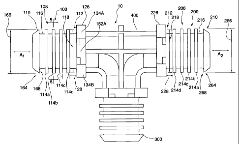
As shown in Figures 1, 2, 3 and 4, one embodiment of the present invention
relates to a
fitting 10 comprising a first connector portion 100 for insertion into a first
pipe 102 having a pre-
determined inner diameter 104 and to be secured within the first pipe 102 by a
first crimp ring
106.
There is also a second connector portion 200 for insertion into a second pipe
202 having a
pre-determined inner diameter 204 and to be secured within the second pipe 202
by a second
crimp ring 206.
In some fittings, such as elbows, there may be only two connector portions,
namely the
first connector portion and a second connector portion. However, in other
fittings, such as T's,
there may be a third connector portion 300 for insertion into a third pipe
(not shown) having a
pre-determined inner diameter and to be secured within the third pipe by a
third crimp ring (not
shown). The characteristics of the third connector portion are substantially
the same as the
characteristics of the first and second connector portions as described
herein.
CA 02505235 2005-04-25
- 5 -
The first connector portion 100 has a first longitudinal, cylindrical portion
108 (as best
seen in Figure 2) for insertion into the first pipe 102. The first cylindrical
portion 108 has a lead
end 110 for insertion into the first pipe 102 and a trailing end 112 opposite
to the lead end 110.
Preferably the second connector portion 200 is substantially the same as the
first connector
portion 100. In particular, preferably the second connector portion 200 has a
second longitudinal,
cylindrical portion 208 for insertion into the second pipe 202. Also, the
second cylindrical
portion 208 has a lead end 210 for insertion into the second pipe 202 and a
trailing end 212
opposite to the lead end 210.
The first connector portion 100 has at least two first spaced-apart concentric
rings 114a
and 114b on a radially-outer portion 116 of the first cylindrical portion 100.
Preferably in a fitting
designed for PEX pipe, there are only two first spaced-apart concentric rings
114a and 114b.
However, in a fitting designed for composite pipe, preferably there are two
sets of first spaced-
apart concentric rings as shown in Figure 2 as elements 114a, 114b, 1 14c and
114d.
The maximum outer radial distance 118 of the first concentric rings 114 is no
greater than
the inside diameter 104 of the first pipe 102.
In a preferred embodiment which is particularly useful for composite pipes,
particularly
composite pipes consisting of an aluminium tube laminated between two layers
of polyethylene, a
first gasket 120 (Figure 3) is positioned between two concentric rings 114a
and 114b on the first
connector portion 100. On the second connector portion 200 a second gasket 220
is positioned
between two concentric rings 214a and 214b. Preferably, there is a second set
of concentric rings
114c and 114d on the first connector portion 100 and a second set of
concentric rings 214c and
214d on the second connector portion 200. In this embodiment, it is preferred
to have another
gasket 122 positioned between the second set of concentric rings 114c and
114d. Similarly, it is
preferred to have another gasket 222 positioned between the second set of
concentric rings 214c
and 214d on the second connector portion 200.
CA 02505235 2005-04-25
- 6 -
Preferably, the gaskets 120, 122, 220 and 222 are 0-rings.
In a further preferred embodiment, each of the first gasket 120 and the other
gasket 122 is
seated to have a maximum outer radial distance 124 no greater than the maximum
outer radial
distance 118 of the first concentric rings 114. Similarly, each of the second
gasket 220 and the
other gasket 222 is seated to have a maximum outer radial distance 224 no
greater than the
maximum outer radial distance 218 of the second concentric rings 214 of the
second connector
portion 200 (the reason why this embodiment is preferred is discussed below).
Referring again to Figure 2, the fitting 10 includes a first stopper ring 126
positioned at
the trailing end 112 of the first cylindrical portion 108 of the first
connector portion 100. The first
stopper ring 126 is positioned a pre-determined longitudinal distance 128 from
the first concentric
rings 114. The pre-determined longitudinal distance 128 is determined such
that when the first
crimp ring 106 is crimped in place the first concentric rings 114 will be
positioned in a
functionally-acceptable position relative to the first crimp ring 106. A
functionally-acceptable
position is one that results in a functionally-acceptable seal, either where
there are no gaskets
when PEX pipe is being connected or when first gasket 120 and other gasket 122
are used in a
preferred embodiment particularly adapted for composite pipe.
Similarly, there is a second stopper ring 226 positioned at the trailing end
212 of the
second cylindrical portion 208 of the second connector portion 200. The second
stopper ring 226
is positioned a pre-determined longitudinal distance 228 from the second
concentric rings 214.
The pre-determined longitudinal distance 228 is determined such that when the
second crimp ring
206 is crimped in place the second concentric rings 214 will be positioned in
a functionally
acceptable position relative to the second crimp ring 206. A functionally-
acceptable position is
one that results in a functionally-acceptable seal, either where there are no
gaskets when PEX pipe
is being connected or when second gasket 220 and other gasket 222 are used in
a preferred
embodiment particularly adapted for composite pipe.
CA 02505235 2005-04-25
- 7 -
Positioned between the first stopper ring 126 and the second stopper ring 226
may be, and
in some embodiments should be, a body portion 400. Preferably the body portion
400 is suitably
ribbed to provide sufficient rigidity, but also sufficient flexibility. A
suitably-ribbed body portion
400 permits the fitting 10 to bend and absorb the strain imparted by pipe
installation, particularly
by composite pipe installation.
T-shaped and elbow-shaped fittings may be designed to act as "springs" to a
certain extent,
thereby absorbing much of the bending momentum which would otherwise have gone
to weaken
points in the fitting 10.
However, in some embodiments, such as compact connectors, there is no body
portion, for
example as seen in Figure 7. In this embodiment, the fitting 10' has a first
connector portion 100'
and a second connector portion 200' which are substantially the same as the
first connector
portion 100 and the second connector portion 200 as previously described,
except that the first
stopper ring 126' and the second stopper ring 226' are the same physical
piece.
In the past, crimp rings have always been positioned such that there is space
between the
end of the pipe and the edge of the crimp ring. Typically there would be a gap
of about 1/8 inch
to 1/4 inch between the end of the pipe and the forward edge of the crimp
ring.
Surprisingly, the inventor has discovered that significant advantages can be
obtained when
the forward edge of the crimp ring is adjacent to the end of the pipe. In
particular, it has been
discovered that if the first pipe 102 is positioned such that the forward end
130 of the first pipe
102 is positioned adjacent to, and preferably abutting against, the first
stopper ring 126 of the first
connector portion 100, and the forward edge 132 of the first crimp ring 106 is
also adjacent to,
and preferably abutting against, the first stopper ring 126, the fitting 10 is
better protected against
bending forces during installation and, therefore, the size of the fitting 10
and the cost of the
fitting 10 can be reduced.
CA 02505235 2005-04-25
- 8 -
A similar situation applies with respect to the second pipe 202, the second
crimp ring 226
and the second stopper ring 226.
Also, when the crimp rings 106 and 206 are adjacent to the ends 130 and 230 of
the pipes
102 and 202, it is much easier to obtain a consistently satisfactory fluid
seal because the gaskets
120, 122, 220 and 222 and/or the concentric rings 114 and 214 can be
positioned so that the crimp
rings 106 and 206 are compressed equally around the gaskets 120, 122, 220 and
222 and/or the
concentric rings 114 and 214.
Preferably, the fitting 10 is made from plastic, and preferably from a
polyphenylsulfone
resin or blend such as RADEL R (trade mark) polyphenylsulfone resin or ACUDEL
(trade mark)
polyphenylsulfone blend.
Preferably, the fittings 10 made from plastic will have the same inner
diameter as ASTM
F- 1974 brass fittings.
The fittings 10 may also be made from other suitable materials, such as metal
alloys
including brass or stainless steel, and in which case at least some of the
advantages of this
invention will still be obtained.
In use, a plumber or other user is provided with fittings 10 to connect the
first pipe 106
having a pre-determined inner diameter 104 to a second pipe 202 having a pre-
determined inner
diameter 204. The fitting 10 is selected such that the sizing of the fitting
10 corresponds to the
inner diameters 104 and 204 of the first and second pipes 102 and 202.
The plumber or user inserts the first cylindrical portion 108 of the first
connector portion
100 of the fitting 10 into the first pipe 102 such that the forward end 130 of
the first pipe 102 is
positioned adjacent to, and preferably abutting against, the first stopper
ring 126 of the first
CA 02505235 2005-04-25
- 9 -
connector portion 100. Preferably the crimp ring 106 is placed loosely around
the first pipe 102
before the first cylindrical portion 108 is inserted into the first pipe 102.
Similarly, preferably the crimp ring 206 is placed loosely around the second
pipe 202 and
then the second cylindrical portion 208 of the second connector portion 200 is
inserted into the
second pipe 202 such that the forward end 230 of the second pipe 202 is
positioned adjacent to,
and preferably abutting against, the second stopper ring 226 of the second
connector portion 200.
The first crimp ring 106 is moved into position around the first pipe 106
adjacent to the
first stopper ring 126, and preferably with the forward edge 132 of the crimp
ring 106 abutting
against the first stopper ring 126. Similarly, the second crimp ring 206 is
moved into position
around the second pipe 202 adjacent to the second stopper ring 226, and
preferably with the
forward edge 232 of the crimping ring abutting against the second stopper ring
226.
The first crimp ring 106 is then crimped to secure the first pipe 102 to the
first connector
portion 100 of the fitting 10. Similarly, the second crimp ring 206 is crimped
to secure the second
pipe 202 to the second connector portion 200 of the fitting 10.
A sought-after benefit of positioning the crimp rings 106 and 206 abutting
against the first
and second stopper rings 126 and 226 is that the crimp rings are always
crimped in the same
position relative to the gaskets and/or concentric rings. This provides a
consistent water seal from
one connection to the next.
In the past, when the crimp ring was positioned 1/8 inch to 1/4 inch from the
end of the
pipe, the crimp ring could end up in various positions relative to the gaskets
and concentric rings.
For example, sometimes only one of the two gaskets would be compressed and
usually the two
gaskets were not compressed equally.
In a preferred embodiment, the concentric rings 114 and 214, as well as the
gaskets 120,
~ '. CA 02505235 2005-04-25
- 10 -
122, 220 and 222, are positioned such that when the forward ends 130 and 230
of the pipes 102
and 202 and the forward edges 132 and 232 of the crimp rings 106 and 206 are
positioned
abutting against the first and second stopper rings 126 and 226, the gaskets
120, 122, 220 and
222, as well as the concentric rings 114 and 214, will be equally or
symmetrically spaced in
relation to the position of the crimp rings 106 and 206, thus providing equal
compression at the
respective gaskets and concentric ring associated with the respective crimp
ring and, therefore, a
preferred water seal.
In a further preferred embodiment of the fitting 10, as best seen in Figure 5,
the first
stopper ring 126 of the first connector portion 100 has an outer periphery
134. At least one first
portion 136 of the outer periphery 134 has a first predetermined radial
distance 138 from the
longitudinal axis A1 of the first connector portion 100 which is greater than
one half the inner
diameter 140 (seen in Figure 6) of the first crimp ring 106 before the first
crimp ring 106 is
crimped.
In this manner, the first crimp ring 106 is prevented from moving
longitudinally beyond
the first stopper ring 126.
Similarly, the second stopper ring 226 of the second connector portion 200 has
a structural
arrangement similar to that of connector portion 100 such that the second
crimp ring 206 is
prevented by the second stopper ring 226 from moving longitudinally beyond the
second stopper
ring 226.
In a further preferred embodiment of the invention, the at least one first
portion 136 of the
outer periphery 134 of the first stopper ring 126 coincides with the outer
periphery 134. In this
embodiment, it is preferred that the outer periphery 134 be circular as shown
by dashed lines 142
in Figure 5 and that the diameter of the circular periphery 142 be greater
than the inner diameter
140 of the first crimp ring 106 before the first crimp ring 106 is crimped.
CA 02505235 2005-04-25
- 11 -
Similarly, the second stopper ring 226 of the second connector portion 200 has
a similar
structural arrangement.
In a further preferred embodiment, the first portion 136 of the outer
periphery 134 is
comprised of four peripheral segments 134A, 134B, 134C and 134D, wherein these
peripheral
segments are arcs of the circular periphery 142.
In a further preferred embodiment, the first stopper ring 126 of the first
connector portion
100 has at least one second portion 144 of its outer periphery 134 at a second
pre-determined
radial distance 146. The second pre-determined radial distance 146 corresponds
to the upper limit
of the maximum inner diameter 148 of a properly-crimped first crimp ring 106
(as shown by
dashed lines 149 in Figure 6).
There are ASTM standards setting the upper limit of the maximum inner diameter
of a
properly-crimped crimp ring. If the crimp ring is not crimped sufficiently
such that the inner
diameter of the crimped crimp ring is greater than the upper limit of the
maximum inner diameter
of a properly-crimped crimp ring, the crimp ring is under-crimped and creates
a risk of earlyjoint
failure.
Thus, in the preferred embodiment being described, if the inner diameter of a
crimped
crimp ring 106 is ever greater than the second pre-determined radial distance
146 at the at least
one second portion 144 of the outer periphery 134 that is a signal or
indication to the worker that
the crimp ring 106 is under-crimped.
Similarly, in this preferred embodiment, the second stopper ring 226 of the
second
connector portion 200 has a similar structural arrangement such that when the
second crimp ring
206 is under-crimped the worker will be able to visually observe the under-
crimping.
In the embodiment shown in Figure 5, there are four second portions 144A,
144B, 144C
CA 02505235 2005-04-25
- 12 -
and 144D of the outer periphery 134 of the first stopper ring 126.
In one embodiment, the second portion 144 has a circular periphery or arcs of
a circular
periphery as shown as dashed lines 150 in Figure 5.
However, for ease of molding and construction, in a preferred embodiment, the
second
portions 144 are included in four flat peripheral portions 152A, 152B, 152C
and 152D.
Although four flat peripheral portions 152 are shown in Figure 5, there could
be only one,
two or three such flat peripheral portions.
Each of the flat peripheral portions 152A, 152B, 152C and 152D has a point
144A, 144B,
144C and 144D that corresponds to the upper limit of the maximum inner
diameter 148 of a
properly-crimped first crimp ring 106.
The four flat peripheral portions 152A, 152B, 152C and 152D are basic linear
measuring
levels. Because plastic pipe varies too much dimensionally to ever be crimped
perfectly round or
even perfectly concentric with the fitting, a circular measuring device such
as the circular
periphery 150 on the first stopper ring 126 is not always ideal.
Because only a few thousandths of an inch may make a difference between a good
and a
bad crimp, the immediate visibility of an improperly-crimped crimp ring will
alert the worker to a
potential problem.
If the pipes 102 and 202 have a colour, such as red, orange or blue, which is
contrasting
with or at least different than the colour of the fitting 10, preferably
white, the under-crimping is
more easily and quickly observed without using additional time-consuming,
cumbersome or
expensive gauging tools for that purpose.
CA 02505235 2005-04-25
- 13 -
If the outer periphery 134 of the first stopper ring 126 were greater than one
half of the
outside diameter of the crimped first crimp ring 106 when crimped there is a
risk that if the
worker did not accurately place the crimping tool (not shown) only around the
crimp ring 106, but
also placed the crimping tool around the first stopper ring 126, the first
stopper ring 126 could be
crushed when the crimping tool crimps the first crimp ring 106.
Therefore, in a preferred embodiment, the first stopper ring 126 has a
predetermined
maximum outer peripheral radial distance from the longitudinal axis Al of the
first connector
portion 100 which is less than one half of the of the minimum outer diameter
of the first crimp
ring 106 when crimped.
Similarly, the second stopper ring 226 of the second connector portion 200 has
a similar
structural arrangement so as to prevent crushing of the second stopper ring
226 by the crimping
tool.
In a further preferred embodiment of the fitting 10, the first stopper ring
126 of the first
connector portion 100 has at least one third portion 158 of its outer
periphery 134 at a third pre-
determined radial distance 160 from the longitudinal axis AI of the first
connector portion 100
that is less than one half the inner diameter 162 of a properly-crimped first
crimp ring 106.
Preferably at least one third portion 158 of the outer periphery 134 of the
first stopper ring
126 on the first connector portion 100 is a slot for example 158A1, 158A2,
158C1 or 158C2, in
the at least one flat peripheral portion 152A or 152C.
Thus, both before the crimp ring 106 is fully positioned and even after the
crimp ring 106
is crimped into position, a worker can look through the slots 158A and 158C to
see whether or not
the end 130 of the pipe 102 is abutting against, or at least adjacent to, the
first stopper ring 126.
CA 02505235 2005-04-25
- 14 -
Similarly, the second stopper ring 226 of the second connector portion 200 has
a similar
structural arrangement so as to allow the worker to view the end 230 of the
second pipe 202 to
ensure that the second pipe 202 abuts against, or is at least adjacent to, the
second stopper ring
226.
In a further preferred embodiment, the first cylindrical portion 108 of the
first connector
100 has a first gripper ring 164 on the radially-outer portion 116 and at the
lead end 110 of the
first connector portion 100.
Similarly, the second cylindrical portion 208 of the second connector 200 has
a second
gripper ring 264 on the radially outer portion 216 and at the lead end 210 of
the second connector
portion 200.
Preferably, the first gripper ring 164 of the first connector portion 100 has
a pre-
determined maximum radial distance 166 which is marginally greater than the
inner diameter 104
of the first pipe 102. Similarly, the second gripper ring 264 of the second
connector portion 200
has a pre-determined maximum radial distance 266 which is marginally greater
than the inner
diameter 204 of the second pipe 202.
Even more preferably, the first gripper ring 164 on the first connector
portion 100 has a
first pipe-gripping edge 168 facing towards the trailing end 112 of the first
cylindrical portion
100. Similarly, the second gripper ring 264 of the second connector portion
200 has a second
pipe-gripping edge 268 facing towards the trailing end 212 of the second
cylindrical portion 200.
The purpose of the first gripper ring 164 and second gripper ring 264 is to
prevent the
fitting 10 from coming out of the respective pipes 102 and 202 during
installation and before
crimping. This feature is particularly useful when the fitting 10 hangs
vertically from one of the
pipes 102 or 202. Because the installer needs both hands to operate the
crimping tool, it is
CA 02505235 2005-04-25
- 15 -
difficult for the installer to also hold the fitting 10 in place without the
first gripping ring 164 and
the second gripper ring 264.
Unfortunately, there is a long standing problem in the plumbing industry with
accidentally
missing connections on the job site. Because of the high number of similar-
looking joints which
a plumber must install quickly during any given day, it naturally happens
that, despite the fitting
being inserted into the pipe, the plumber inadvertently misses crimping one of
the pre-positioned
crimp rings on that connection.
Usually a system pressure test is performed when the job is completed to
detect these
types of over-looked or forgotten crimps. During these tests, the first
gripper ring 164 and the
second gripper ring 264 can act as effective, but misleading, seals. This is
especially so if the first
and second pipe-gripping edges 168 or 268 grip into the pipes 102 and 202 when
the fitting 10 is
fully inserted.
To eliminate this situation, a portion 170 of the first gripper ring 164 is
provided which
has a pre-determined radial distance 172 from the axis A, of the first
connector portion 100 that
is less than the one half of the inner diameter 104 of the first pipe 102.
Similarly, the second gripper ring 264 of the second connector portion 200 has
a second
portion 270 having a pre-determined radial distance 172 from the axis A2 of
the second connector
portion 200 that is less than one half of the inner diameter 204 of the second
pipe 202.
The second portions 170 and 270 ensure a water path by which water can escape
from the
fitting 10 during a system pressure test if the crimp rings 106 or 206 are not
crimped.
The second portions 170 and 270 are completely filled with pipe material when
the
crimping operation is actually performed.
CA 02505235 2005-04-25
- 16 -
Preferably the second portions 170 and 270 are slots molded into the fitting
10 at the time
of manufacture.
Preferably there are two such slots that are diametrically opposed around the
first gripper
ring 264 and two diametrically opposed slots around the second gripper ring
264.
Also, in order to assist in ensuring that uncrimped crimp rings do not go
undetected during
a system pressure test, in a further preferred embodiment, as noted above,
each of the first gasket
120 and the other gasket 122 is seated to have a maximum outer radial distance
124 no greater
than the maximum outer radial distance 118 of the first concentric rings 114.
Similarly, each of
the second gasket 220 and the other gasket 222 is seated to have a maximum
outer radial distance
224 no greater than the maximum outer radial distance 218 of the second
concentric rings 214 of
the second connector portion 200.
If any of the gaskets 120, 122, 220 and 222 has a maximum outer radial
distance 124
greater than the maximum outer radial distance 118 or 218 of the concentric
rings 114 or 214,
such gasket would form an effective, but misleading, seal during the system
pressure test thereby
allowing the plumber to over-look an uncrimped crimp ring. Therefore, in order
to avoid this
situation, the maximum outer radial distances 124 and 224 of the various
gaskets 120, 122, 220
and 222 are designed and made to have maximum outer radial distances 124 and
224 no greater
than the maximum outer radial distances 118 and 218 of the first concentric
rings 114 and the
second concentric rings 224, respectively.
In use, a plumber, or other suitable worker, uses the fitting 10 to connect
the first pipe 102
having a pre-determined inner diameter 104 to a second pipe 202 having a pre-
determined inner
diameter 204. Firstly, a fitting 10 as described herein is provided to or
obtained by the plumber.
The plumber inserts the first cylindrical portion 108 of the first connector
portion 100 of the
fitting 10 into the first pipe 102 such that the forward end 130 of the first
pipe 102 is adjacent to,
and preferably abutting against, the first stopper ring 126.
= CA 02505235 2005-04-25
- 17 -
The plumber then inserts the second cylindrical portion 208 of the second
connector
portion 200 into the second pipe 202 such that the forward end 230 of the
second pipe is adjacent
to, and preferably abutting against, the second stopper ring 226.
The plumber then positions the first crimp ring 106 around the first pipe 102
adjacent to,
and preferably abutting against, the first stopper ring 126 of the first
connector portion 100. The
plumber similarly positions the second crimp ring 206 around the second pipe
202 adjacent to,
and preferably abutting against, the second stopper ring 226 of the second
connector portion 200.
The plumber then crimps the first crimp ring 106 around the first pipe 102 to
secure the
first pipe 102 to the first connector portion 100 of the fitting 10.
Similarly, the plumber crimps
the second crimp ring 206 around the second pipe 202 to secure the second pipe
202 to the second
connector portion 200 of the fitting 10.
If the fitting 10 is a "T" and has a third connector portion 300, the plumber
engages in
similar steps to position and crimp a third crimp ring (not shown) around the
third pipe.
In another aspect, this invention resides in providing a pipe assembly
comprising the
fittings as described herein wherein the first connector portion 100 is
inserted into the first pipe
102 and secured within the first pipe 102 by a first crimp ring 106 (as shown
in Figure 1), and
wherein the second connector portion 200 is inserted into the second pipe 202
and secured within
the second pipe 202 by a second crimp ring 206.
It will be understood that, although various features of the invention have
been described
with respect to one or another of the embodiments of the invention, the
various features and
embodiments of the invention may be combined or used in conjunction with other
features and
embodiments of the invention as described and illustrated herein.
CA 02505235 2005-04-25
- 18 -
Although this disclosure has described and illustrated certain preferred
embodiments of
the invention, it is to be understood that the invention is not restricted to
these particular
embodiments. Rather, the invention includes all embodiments which are
functional or
mechanical equivalents of the specific embodiments and features that have been
described and
illustrated herein.