Note: Descriptions are shown in the official language in which they were submitted.
CA 02505248 2005-05-05
WO 2004/043603 PCT/GB2003/004886
1
AN ELECTROSTATIC PRECIPITATOR
The present invention is concerned with an electrostatic precipitator. The
present
invention is particularly, although not exclusively, directed to an
electrostatic precipitator
suitable for the collection and analysis of an airborne suspension of
particles, including
micro-organisms, in an environment.
The analysis of airborne particles in an environment generally requires
sampling large
volumes of air. Current collection techniques often rely on the acceleration
of air to very
high velocities in order to utilise the differential momentum between
particles and air to
impact the particles to a collection surface or liquid. Such impaction
techniques,
however, generally require a very high energy input and are limited in their
ability to
separate small particles (below 1 pm).
The collection of particles at an electrode surface in an electrostatic field
is a well-known
phenomenon underlying the use of electrostatic precipitators to separate dust
and smoke
particles from an environment. In a simple form of electrostatic precipitator,
a high
voltage is applied to a wire on a longitudinal axis of an earthed cylinder
through which an
air flow is maintained. A corona discharge is formed at the wire and ions
having the
same polarity as the wire are repelled toward the inner surface of the
cylinder. The
electric field between the wire and the cylinder is, however, distorted by the
relative
permittivity of the particles compared to the surrounding air and this leads
to an
aggregation of ions at the particles, which continues until the field
distortion is balanced
by the charge on the particle. The charged particles experience a force in the
electric
CA 02505248 2005-05-05
WO 2004/043603 PCT/GB2003/004886
2
field carrying them to the earthed cylinder where they adhere. The particles
may be
dislodged from the surface of the cylinder by vibration or by subsequent
passage of a
collecting fluid.
S Electrostatic precipitators of the prior art are, however, mostly concerned
with scrubbing
of effluent gases on an industrial scale and so little attention has been paid
to their
application to the problem of optimum sampling of particles from an airborne
environment. Indeed, most electrostatic precipitators are unsuitable for the
efficient
collection of particles from an environment, even when miniaturised, in that
the
collecting surface of the cylinder is relatively large and consequently only
dilute particle
samples can be practically obtained.
One approach to the problem of efficient collection of particles from an
environment
minimises the amount of collecting fluid used in a miniaturised electrostatic
precipitator
(InnovaTek, USA). The precipitator comprises a number of collecting plates
having
micro-machined channels to which the particles, charged by the release of
electrons to the
air flow, are preferentially deposited. The particles are collected by the
passage of the
collecting fluid within the channels.
An alternative approach, developed by Applicant, attempts to tightly focus
particles
charged by corona discharge field to a point surface. In this arrangement, the
earthed
electrode comprises a ring electrode allowing charged particles to emerge with
the air
flow. The charged particles enter an additional electric field provided by an
electrode
CA 02505248 2005-05-05
WO 2004/043603 PCT/GB2003/004886
3
configuration, known to the art as an electrostatic lens. In one configuration
of
electrostatic lens a number of electrode rings, of identical polarity to the
particles, are
concentrically arranged above an earthed, pin counter electrode so as to
provide an
electric field constraining the particles to the counter electrode.
The arrangement is, however, unsatisfactory in that, even when particle size
is increased
by condensation, the extent of charge developed on the particles at desired
airflows is
non-uniform. Further, the strength of the focussing field acting on the
particles at desired
operating voltages and air flow rates often either fails to overcome drag
effects or
alternatively arrests the emergence of the particles from the charging field.
Consequently, even where the number of focussing rings has been optimised, the
arrangement allows the focussing of only a proportion of particles passing the
earthed
counter electrode.
European patent application EP 0 239 865 discloses apparatus for electrostatic
collection
of particles from a gas stream. The apparatus comprises a first cylindrical
electrode
defining a number of apertures surrounding a second, cylindrical counter
electrode. An
ion source is provided by a plurality of point electrodes associated with the
apertures in
the first cylindrical electrode. The counter electrode is maintained at a
negative potential
whilst the first cylindrical electrode is grounded so that ion efflux from the
positive point
electrodes is directed to the counter electrode. Ionised particles travel
towards the
counter electrode but are, on the whole, collected in a collector arranged
below the
electrodes.
CA 02505248 2005-05-05
WO 2004/043603 PCT/GB2003/004886
4
The present invention generally seeks to allow for the efficient collection
and analysis of
particles in an environment by providing an improved electrostatic
precipitator which is
capable of efficiently focussing particles to a point surface.
The present invention starts from the realisation that non-uniform charging of
particles in
an electrostatic field generated by a corona discharge is due to a
concentration gradient of
ions developed between the point electrode and the counter electrode.
Consequently,
particles adjacent the counter electrode, are less likely to develop charge
than particles
adjacent the point electrode. An arrangement providing an electrostatic field
in which the
ion concentration gradient is removed or reversed may therefore be expected to
allow
improved focussing of the particles.
Accordingly, the present invention provides an electrostatic precipitator
comprising a
conduit for the passage of an air flow containing particles and means
generating an
electrostatic field, substantially orthogonal to the airflow, and a supply of
ions, capable of
charging the particles, in which the generating means comprise a point
electrode and a
two dimensional surface electrode characterised in that the two dimensional
surface
electrode comprises an ion source and the point electrode comprises a counter
electrode
and in that the counter electrode is earthed.
It will be understood that, in the arrangement of the present invention, ion
transport from
the ion source is directed to a point electrode and that consequently the
concentration
CA 02505248 2005-05-05
WO 2004/043603 PCT/GB2003/004886
gradient of ions between the two dimensional surface electrode and point
electrode is
reduced compared to most prior art arrangements.
In a preferred embodiment of the present invention, the two dimensional
surface
5 electrode comprises an ion source known to the art as a plasma charger. The
use of a
plasma charger as an ion source avoids field concentration and minimises
corona wind,
which can lead to turbulence in the gas stream and affect particle deposition.
In a typical charger, the electrode comprises a strip of insulating material
sandwiched
between two strips of conducting materials, one of which is of substantially
lower surface
area than the insulating strip. An alternating potential difference applied to
the charger
generates an emission of ions from the insulating strip at or adjacent the
contacting edge
of the smaller conducting strip.
Preferably, the length of the contacting edge is maximised so as to provide
the greatest
possible concentration of ions over the greatest extent of the conduit means.
In a
particularly preferred arrangement, the contacting edge of the smaller
conducting strip is
maximised by the adoption of a castellated configuration.
The plasma electrode may also be configured as a single electrode or as a
plurality of
single polarity electrodes. In some embodiments of the present invention the
electrode
comprises a plurality of electrodes.
CA 02505248 2005-05-05
WO 2004/043603 PCT/GB2003/004886
6
However, in a preferred embodiment, the two dimensional surface electrode
comprises a
single hollow cylinder formed from the castellated plasma electrode, which may
be
conveniently arranged within a cylindrical conduit of substantially similar
cross sectional
area. In this embodiment an electrostatic field can be maintained across a
substantial area
S and length of the conduit means.
It will be understood that the term "point electrode" is not necessarily
limited by any need
to discharge ions. Rather the term is used to convey the meaning that the
counter
electrode provides a low surface area in comparison to the two dimensional
surface
electrode. The point electrode may, for example comprise a wire or a non-
tapering rod or
cylinder. Preferably, however, the point electrode comprises a pin.
In a preferred embodiment of the present invention the point electrode is co-
axially
mounted with the conduit. However, other arrangements, in which the
longitudinal axis
of the electrode is offset from the longitudinal axis of rotation of the
conduit are possible.
It will be understood that the charging of particles in the electrostatic
field and the force
acting on the charged particles will be determined by a number of variables,
including the
voltage applied to the electrodes and the rate of airflow. These parameters
are selected so
as to maximise the charge developed on the particles.
Preferably, the particles are charged to their Pauthenier limit. Still more
preferably, the
airflow is substantially free from turbulence and drag effects acting on
particles moving
CA 02505248 2005-05-05
WO 2004/043603 PCT/GB2003/004886
7
across the electrostatic field are minimised. It will therefore be apparent
that proper
selection of these parameters can enable forces acting on the charged
particles to
overcome drag effects and deflect the particles toward the point electrode.
The present invention provides that the particles are mostly deposited on the
counter
electrode. It will be apparent that the earthed counter electrode provides,
through the
absence of stored charge, the significant advantage that particles can be
easily collected
from the surface of electrode by simple collection means.
Although, the particles may be collected by any convenient means, in a
preferred
embodiment of the present invention, the counter electrode includes means for
delivering
a liquid to the surface of the electrode. Preferably, the delivery means
comprise an
interior channel enabling particles to be collected by the progress of the
liquid over the
exterior surface of the electrode under gravity. The deposited particles are
preferably
collected at time intervals.
The present invention provides an electrostatic precipitator in which the
electrostatic and
ion field not only leads to more uniform particle charging but also focuses
the charged
particles toward the counter electrode.
The feature that the counter electrode is earthed not only facilitates the
collection of
particles deposited on the point electrode, but also enables monitoring of the
two
CA 02505248 2005-05-05
WO 2004/043603 PCT/GB2003/004886
8
dimensional electrode by a simple micro-ammeter. Further a high voltage power
supply
of only a single polarity is required.
The present invention provides an improved electrostatic precipitator in which
particles
may be collected from an electrode of substantially reduced surface area. The
uniform
charging of substantially all particles enables them to be collected from the
counter
electrode to a small liquid volume so enabling rapid sampling and analysis of
particles in
an airborne environment.
Another advantage of the invention is that high inputs of air may be analysed
without the
need for rapid acceleration and so low operating powers are used. Further the
precipitator
may be portable.
In some embodiments of the present invention, the precipitator may
nevertheless
comprise second means for generating an electrostatic field. In these
embodiments the
second electrostatic field is a focussing field provided downstream from the
first field.
In one embodiment, the second generating means comprise a single point
electrode which
is co-axially mounted with the conduit at a position downstream from the first
point
electrode. Preferably, the second point electrode is also an earthed
electrode.
In another embodiment, the second generating means further comprise an
electrode of
suitable polarity to deflect the charged particles to the second point
electrode. The
CA 02505248 2005-05-05
WO 2004/043603 PCT/GB2003/004886
9
electrode may be adapted as a plurality of single polarity electrodes.
Preferably,
however, the second generating means comprise a ring electrode co-axially
mounted with
the conduit.
In a further embodiment of the present invention, the second generating means
comprise
a plurality of ring electrodes of single polarity, each co-axially mounted
with the conduit.
Preferably, two ring electrodes are used. Still more preferably, the ring
electrodes are of
differing cross sectional area with the smallest ring being arranged furthest
from the first
point electrode.
Particles deposited on the second point electrode may be collected by any
convenient
means and in particular by means previously described for the counter
electrode.
The present invention will now be described with reference to a number of
embodiments
and the accompanying drawings in which
Figure 1 is a schematic illustration of the electrostatic field between a
point
electrode and a plane surface counter electrode;
Figures 2 a) and 2 b) show a plan view of a precipitator of a prior art
precipitator
comprising a point electrode and a cylindrical counter electrode. The
resultant field lines
and equipotentials are shown.
Figures 3 a) and 3 b) show a plan view of a preferred embodiment of the
precipitator of the present invention. The resultant field lines and
equipotentials are
shown.
CA 02505248 2005-05-05
WO 2004/043603 PCT/GB2003/004886
Figure 4 is a cross sectional elevation view of the embodiment of Figure 3;
Figure S is a cross sectional elevation view of another embodiment of the
present
invention; and
Figure 6 is a cross sectional elevation view of a fiuther embodiment of the
present
5 invention.
Having regard now to Figure 1, an electrostatic field produced between a point
electrode
11 to which a high voltage has been applied and a plane surface electrode 12
has field
lines 13 (broken) that outwardly diverge from the point electrode 11. A
potential
10 gradient, indicated by the progress of lines of equipotential 14 (fizll)
from the point
electrode 11, results in the transport of ions and particles 15 charged in the
field along the
electric field lines 13 to the plane surface electrode 12.
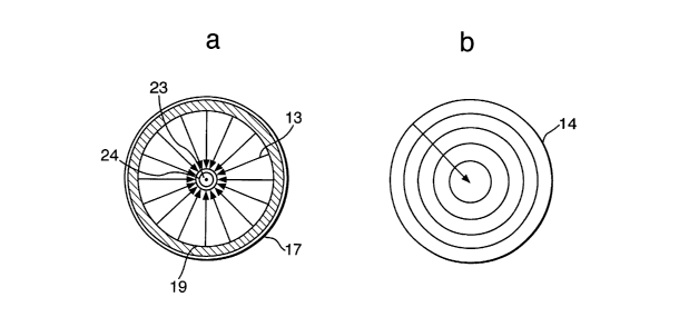
Figures 2 a) and 2 b) shows the resultant electric field lines 13 and
equipotentials 14
when the plane surface electrode 12 is configured as a cylinder electrode and
the point
electrode 11 co-axially mounted therewith. The arrangement, which forms the
basis of a
number of prior art precipitators, results in an electrostatic field in which
the electric field
lines radially diverge from the point electrode 11. The electrostatic field is
associated
with a potential gradient that results in the transport of ions and particles
15 charged in
the field to the ring electrode.
Referring now to Figure 4, an electrostatic precipitator according to the
present invention,
generally designated 16, comprises a hollow tube 17 having an inner surface 18
on which
CA 02505248 2005-05-05
WO 2004/043603 PCT/GB2003/004886
11
a plasma charger electrode 19 is provided. The plasma charger 19 comprises a
strip 20 of
insulating material sandwiched between two metal plates 21 across which a
large
alternating potential difference is applied. One plate 21 (shown) is
castellated so as to
provide a contacting edge with the insulating material 20 that enables the
generation ions
S over a large surface area of the tube 17.
A portion of tube 17 defines apertures for fi-ictional engagement with spokes
22 of a
wheel member 23. Wheel member 23 provides a central aperture for frictional
engagement with an insulating rod member 24. A portion of the cylindrical rod
member
24 is covered with a metal layer 25 and acts as an earthed counter electrode.
The rod
member 24 is arranged so that the counter electrode 25 is positioned in the
tube 17 at a
point opposite the plasma electrode 19. A blower 26 is co-axially mounted with
tube 17
below rod member 24.
Figures 3 a) and b) show the resultant electric field lines 13 and
equipotentials 14 the
potential difference is applied to the plasma electrode. As may be seen, the
electrostatic
field is constrained by the size of the counter electrode 25 and is associated
with a
potential well directed to the counter electrode 25.
In use, air containing uncharged particles 1 S is drawn into the tube 17 by
the blower 26
where it travels through wheel member 23 into the electrostatic field between
the plasma
electrode 19 and the counter electrode 25. The airflow and the potential
difference
applied to the plasma electrode are chosen so that particles 15 entering the
field become
CA 02505248 2005-05-05
WO 2004/043603 PCT/GB2003/004886
12
rapidly charged to their maximum limit enabling the force acting on them to
overcome
drag effects caused by the airflow. Charged particles 15 are deflected to the
counter
electrode 25 where they aggregate.
Referring now to Figure 5 a second embodiment of the present invention
comprises the
features of the preferred embodiment except that rod member 24 extends within
the tube
17 to a greater extent. A second portion of the cylindrical rod member 24 is
covered with
a metal layer 27. The metal layer 27 is earthed and acts as a second counter
electrode. In
this embodiment a second electrostatic field exists between the plasma
electrode 19 and
the second counter electrode 27. In use, the airflow is increased so that the
charged
particles 15 are deflected by the second electrostatic field and are deposited
at the second
counter electrode 27.
It will be understood that the exact positioning of the second counter
electrode 27 is of
some consequence and is to some extent determined by the strength of each
electrostatic
field and the rate of airflow.
Refernng now to Figure 6, a further embodiment of the present invention also
comprises
the features of the second embodiment. However, the focussing field is now
provided by
an arrangement comprising the second counter electrode 27 and a number of ring
electrodes 28. The arrangement is of a type similar to a known electrostatic
lens suitable
for focussing electrons in vacuo. However, arrangements in which multiple ring
electrodes 28 are provided are no more effective for focussing particles of
significant
CA 02505248 2005-05-05
WO 2004/043603 PCT/GB2003/004886
13
mass than arrangements involving two ring electrodes 28. Consequently this
embodiment provides two ring electrodes 28 of differing size which are co-
axially
mounted with the tube 17 toward the second counter electrode 27. The smaller
ring
electrode 28 is mounted closest the counter electrode 27 so as to provide a
focussing field
for charged particles 15 existing the first electrostatic field. The ring
electrodes 28 are
charged to the same polarity as the charged particles 15 so that the particles
exiting the
first electrostatic field and entering the second are deposited on the second
counter
electrode 27.
The exact positioning of the second counter electrode 27 and the ring
electrodes 28, is of
some consequence and is to some extent determined by the strength of each
electrostatic
field and the rate of airflow.
The present invention has been described in relation to a number of simple
embodiments
and it will be apparent that such variations as may be expected within the art
are included
within its scope. In particular, the focussing field may be formed by a
cylindrical and
point electrode arrangement. Further, the precipitator may also comprise a
control
circuitry for controlling its operation. A microprocessor may also be provided
so as to
enable calculation of the concentration of particles in an environment by
calibration of
the number of particles obtained at a particular airflow with currents
obtained at the
counter electrode.