Note: Descriptions are shown in the official language in which they were submitted.
CA 02505349 2005-05-06
WO 2004/043791 PCT/US2003/034321
APPLICATOR PACKAGE WITH DISPOSABLE APPLICATOR PAD ASSEMBLY
BACKGROUND OF THE INVENTION
s Field of the Invention:
The present invention relates to product storage packages that include
applicator means. In particular, the present invention is directed to bottles
or jars for
dispensing fluid products such as liquids, creams or powders through an
applicator
pad on one end of the container. More particularly, the invention is directed
to a
to disposable applicator pad assembly for such a container.
Description of the Prior Art:
Product packages that combine a product storage reservoir and a built in
porous applicator pad are known, as shown, for example in U.S. Pat. Nos.
3,481,676,
is 4,133,614 or 5,577,851. A problem with such packages is that the applicator
pad
may become soiled, clogged, worn or damaged before the contents of the product
storage reservoir are fully utilized. Since the applicator pads are often
permanently
fixed to the package, cleaning, repairing or replacing the applicator pad may
be
impractical or impossible without compromising the airtight qualities or
structural
2o integrity of the package proper.
Lotion applicators with removable applicator pads are also known. For
example, U.S. Pat. No. 5,931,591 discloses a removable applicator cap with a
reduced diameter opening surrounded by an elastomeric band . While this
2s arrangement may be suitable for a lotion applicator having a head portion
that is
substantially larger in dimension than a supporting neck portion, it is not
suitable for a
typical consumer package having an applicator pad that is the same size as or
smaller than the neck of the package. U.S. Pat. No. 6,045,279 discloses a
lotion
applicator with a sponge assembly that is removable and replaceable. The
sponge
3o assembly is fastened to the lotion applicator by way of a hook and pile
type fastening.
While this arrangement may be suitable for a lotion applicator as shown, in
terms of
materials and manufacturing, it is not sufFiciently cost effective for use in
mass
production of product packaging that includes an applicator pad. It is also
noted that
for at least the following reasons, lotion applicators such as those described
above
3s are, from an economic standpoint, substantially different devices from
product
CA 02505349 2005-05-06
WO 2004/043791 PCT/US2003/034321
packages. In general, higher costs (including materials, manufacturing and
retail) are
tolerated for lotion applicators such as those shown in the references above
because
they are durable and may be refilled to be used innumerable times. In
contrast, the
cost of a typical product package must be kept to a minimum because, among
other
reasons, it is generally disposed of after substantially all of a product
stored within has
been dispensed.
Accordingly, there is a need for a cost effective, mass produce-able product
package having an applicator pad that is easily removable for cleaning, repair
or
to replacement.
BRIEF SUMMARY OF THE INVENTION
The present invention is directed to a mass produce-able product package
having an applicator pad that is easily removable for cleaning, repair or
replacement.
is The applicator package includes a container for storing a consumer product
such as,
for example, a cosmetic, a lotion, a personal care product or a
pharmaceutical. A
screen is supported on the container and spans an opening in the container. A
disposable applicator pad assembly sits over the screen. The applicator pad
assembly includes a porous foam pad with an elastomer strip fixed to its
perimeter. A
2o retaining ring that is selectively attachable to the container (either
directly to the
container or indirectly to the container by way of an intervening part, e.g.,
the screen
member) is dimensioned to compress at least an outer annular portion of the
elastomer strip in sealing engagement against the container or screen to
secure the
applicator pad assembly to the package.
The invention is also directed to the applicator pad assembly including the
porous foam pad with the elastomer strip fixed to the perimeter of the pad.
The
elastomer strip may be fixed to the porous foam pad by, for example, adhesion,
bonding, welding or overmolding. In any case, the elastomer strip is fixed to
the
3o porous foam pad such that when the pad assembly is secured on a package by
a
retaining ring, the elastomer strip is compressed to form an impervious seal
between
the ring and the structure supporting the ring.
CA 02505349 2005-05-06
WO 2004/043791 PCT/US2003/034321
A selectively removable cap may also be provided for the package. The cap is
fastened to the package by, for example, friction-fit, snap-fit, threads or
bayonet
means. A skirt depending from the cap forms an impervious seal with the
package by
contacting a portion of the elastomer strip of the applicator pad assembly.
s
The invention provides a means of replacing or cleaning the applicator pad as
the product is being consumed while maintaining the structural integrity and
impermeable qualities of the package. In this manner, a hygienic condition may
be
maintained on the applicator surface.Y Additionally, the user has an
opportunity to
to change the application characteristics of the package by changing the
applicator pad
assembly.
BRIEF DESCRIPTION OF THE DRAWINGS
FIG. ~ is a cross-sectional view of the applicator package incorporating the
invention;
is
FIG. 2 is a cross-sectional view of an applicator pad assembly according to
the
invention;
FIGS. 3a - 3f are partial sectional views of various embodiments of the
applicator pad
2o assembly according to the invention;
FIG. 4 is a plan view of the applicator pad assembly of FIG. 2;
FIG. 5 is a perspective view of an alternative embodiment of the applicator
package;
FIG 6 is a detail view of a portion of the applicator package shown in FIG. 5;
and
FIG. 7 is a detail view of an alternate embodiment of the applicator package.
3o DETAILED DESCRIPTION OF THE INVENTION
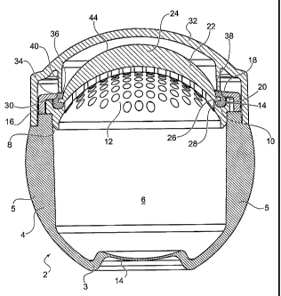
Referring now to FIG. 1, an applicator package, shown generally at reference
number 2, is disclosed comprising a container 4 with a bottom wall 3 and
peripheral
wall 5 defining a storage reservoir 6 for storing a quantity of product (not
shown). The
container 4 has a dispenser opening 8 for dispensing the product from the
storage
3
CA 02505349 2005-05-06
WO 2004/043791 PCT/US2003/034321
reservoir 6. A screen member 10 spans the dispenser opening 8 and is
preferably
impermeably attached to the container 4. The screen member 10 may, after
product
has been provided to the storage reservoir 6, be attached to the container
permanently, by, for example, bonding, welding or molding it in place.
Alternatively,
s the screen member 10 may be removably attached to the container by way of,
for
example, a friction fit, an interference fit, a snap fit, cooperating threads
or a suitable
bayonet arrangement. Such attachments and the means for making them
impermeable are well known in the arfi of package construction. A perforated
portion
12 of the screen member 10 is positioned approximately centrally in the screen
to member 10 to be in fluid communication with the storage reservoir 6 by way
of the
dispenser opening 8.
A first annular bearing surface 14 is defined about the perforated portion 12
on
the screen member 10. The first annular bearing surface 14 is at least in part
is upwardly directed. While it is preferred that the first annular bearing
surface 14 be
defined on the screen member 10, it will be understood by those skilled in the
art that
the first annular bearing surface 14 could alternatively be defined on an
upwardly
directed surface of the container 4, such as, for example, the surface 16 on
which the
screen member 10 rests.
A retaining ring 18 is selectively attachable to the container 4, about the
perforated portion of the screen member 10. It will be understood that by the
phrase
"attachable to the container" it is meant that the retaining ring 18 will be
either
attachable to the container 4 indirectly by way of the screen member 10 as
shown, or,
2s alternatively, the retaining ring 18 will be attachable to the container 4
with other
intervening parts or no intervening parts. The retaining ring 18 is attachable
to the
container 4 by way of a friction fit, an interference fit, a snap fit,
cooperating threads
(as shown generally at reference number 51 in FIG. 7) or a suitable bayonet
arrangement. Alternatively, the retaining ring 18 may be incorporated into a
retainer
3o assembly 19 attached to the container 4 (see FIGS. 5 and 6). The retainer
assembly
19 includes a base ring 21 attached to the container 4 by conventional means,
e.g.,
cooperating threads, friction fit, interference fit, bayonet, chemical or
physical
bonding, etc. The retaining ring 18 is connected to the base ring 21 by a
hinge-type
connection 15, for example, a living hinge 17, that allows the retaining ring
18 to pivot
4
CA 02505349 2005-05-06
WO 2004/043791 PCT/US2003/034321
from an open position away from the screen member to a closed position about
the
periphery of the screen member. A snap fit engagement of the retaining ring 18
to the
base ring 21 holds the retaining ring 18 in the closed position securely about
the
periphery of the screen member. In the embodiment shown, the snap fit
engagement
s comprises an outwardly directed bead 23 engaging an inwardly directed
channel 37
(see FIG. 6). The bead 23 projects outwardly from an annular skirt 35
depending
from retaining ring 18. The channel 37 is formed in an inwardly directed wall
of base
ring 21.
io The retaining ring 18 defines a second annular bearing surface 20
cooperatively dimensioned and adapted to face the first annular bearing
surface 14
when the retaining ring 18 is closely attached on the screen member 10. The
second
annular bearing surface 20 is at least in part downwardly directed.
is As shown in FIG. 1, a disposable applicator pad assembly 22 is provided
over
the screen member 10. The disposable applicator pad assembly 22, shown in
FIGS.
2 and 4 separated from the package 2 for greater clarity, has a porous foam
pad 24
dimensioned to cover and be at least partially supported by the perforated
portion 12
of the screen member 10. Continuously along a perimeter edge 26 of the porous
2o foam pad 24, at least one elastomer strip 28, i.e., a strip made of an
elastomeric
material, is securely fixed. The at least one elastomer strip 28 is fixed to
the
perimeter edge 26 of the foam pad 24 by, for example, welding, adhering,
bonding or
molding. Preferably, the strip 28 is fixed, as best shown in FIG. 2, about
three sides
25, 27, 29 of the perimeter edge 26 of the foam pad 24. Alternatively, the
strip 28 is
2s fixed to one or two of the three sides 25, 27, 29 of the perimeter edge 26,
as shown in
the alternative embodiments of FIGS. 3a-3f. At least an outer annular portion
30 of
the strip 28 is dimensioned to be received and compressed in sealing
engagement
between the first annular bearing surface 14 and the second annular bearing
surface
20 when the retaining ring 18 is secured to the container 4 in a position
about the
3o perimeter of the applicator pad assembly 22. A portion of the perimeter
edge 26 of
the foam pad 24 may also be compressed between the bearing surfaces 14 and 20.
Additionally, the strip 28 may be provided with channels or other suitable
surface
details to accommodate one or more bearing surfaces. For example, in the strip
28
CA 02505349 2005-05-06
WO 2004/043791 PCT/US2003/034321
shown in FIGS. 2 and 6, channels 31 and 33 are provided to accommodate the
second and third annular bearing surfaces 20 and 34, respectively.
While the screen member 10 and applicator pad assembly 22 are shown to
provide a dome shaped (i.e., convex) application surface 44, it will be
understood that
the application surface 44 may take any suitable shape or form including but
not
limited to, flat, concave, wavy, ridged, etc., by merely molding the desired
shape of
the foam and selecting a suitable and/or corresponding shape for the
supporting
screen member.
to
A selectively removable cap 32 may be provided for attachment to the
container 4, either directly as shown, or by way of the screen member 10, the
retaining ring 18 or another intervening member (not shown). The cap 32 is
attached
by well known means, such as, for example, friction fit, snap fit, cooperating
threads
is (as shown generally at reference number 53 in FIG. 7) or a bayonet-type
connection.
When the cap 32 is attached to the container 4 by way of threads or a bayonet-
type
mount, and the retainer ring 18 or retainer assembly 19 is also attached by
way of
threads or a bayonet mount, preferably the threads or bayonet-type mount of
each of
the cap and the retainer ring 18, or the cap and the retainer assembly 19, are
20 oppositely pitched, such that removing the cap will not loosen the retainer
ring or
retainer assembly.
The cap is dimensioned to cover and protect the applicator pad assembly 22
and application surface 44 when the package 2 is not in use. A third annular
bearing
2s surface 34 is defined by the cap 32 and adapted to contact in sealing
engagement an
inner annular portion 36 of the elastomer strip 28. In the preferred
embodiment, the
third annular bearing surface 34 is provided on a lower end 38 of a sealing
skirt 40
depending from the cap 32. When the cap 32 is securely attached to the
container,
the third annular bearing surface 34 contacts in sealing engagement the inner
annular
3o porkion 36 of the elastomer strip 28.
The package is preferably manufactured using conventional manufacturing
methods and assembly practices, such as, for example, injection molding and
extrusion blow molding. The container, screen member, retainer ring and cap
may be
CA 02505349 2005-05-06
WO 2004/043791 PCT/US2003/034321
made from materials such as, for example, resins or elastomers, including but
not
limited to polypropylene (PP), polyethylene (PE) (high or low density), PET,
or a
combination of the foregoing. For example, a compound of PP and PE can be used
in a ratio of 70/30, respectively, or 50/50. A material that is particularly
well suited for
making the screen member is polyoxymethylene (POM), such as, for example,
Delrin,
a registered trademark of DuPont de Nemours, Wilmington, Delaware.
A suitable material for the porous foam pad 24 is any closed or open cell foam
with any conventional pore size made of a material that is compatible with the
product
io to be dispensed. Examples of such foam include polyester, polyether,
polyvinyl
chloride and polyurethane. Polyurethane is the preferred material. Although at
a
minimum, the foam material must have sufficient porosity to permit passage of
the
product to be stored within the package, the porosity of the material may be
selected
to provide any flow rate between a relatively high flow rate and a relatively
low flow
is rate. For example, adequate quantities of a cosmetic formula such as a
fluid
foundation or a skincare cream can pass through a low density, small open cell
polyurethane foam having a thickness of 3mm. In any case, by taking into
account
the type of foam material, the density of the foam and the thickness of the
foam pad,
the flow rate of a particular formula through the foam material can be
determined
2o without undue experimentation. Though less desirable, alternatively, the
formulation
of a particular product may be adjusted to flow at a particular rate through a
particular
density of foam material.
A suitable material for the elastomer strip is elastomer thermoplastic that is
2s capable of being adhered to, molded to or welded to the selected foam
material of the
applicator pad. The material for the-elastomer strip and the material for the
porous
foam pad must be selected to have chemical properties which will permit a
secure
bond when the elastomer and the foam are adhered, molded or welded together. A
preferred elastomer thermoplastic that is known to exhibit good adhesion to
3o polyurethane foams, particularly in the over-molding process, is available
from
THERMOPLASTIQUES COUSIN-TEISSIER S.A., Tiffauges, France. The particular
elastomer thermoplastic is identified by the manufacturer as tefabloc
(trademark) TE
FI 817 52A.
CA 02505349 2005-05-06
WO 2004/043791 PCT/US2003/034321
While it is contemplated that the material of the porous foam pad will be
selected to permit the free flow of a particular formula by capillary action,
the
applicator package 2 may optionally be provided with means for pushing product
from
within the storage reservoir 6. The means may comprise a wall portion of the
container 4 that is resiliently deformable such that the volume of the storage
reservoir
6 is reduced sufficiently to move a quantity of product through the perforated
portion
12 of the screen member 10 and into and/or through the foam pad 24. The means
for
pushing may comprise a deformable panel 40 molded integrally into the bottom
wall 3
of the container, as shown, or a similar deformable panel 40 located on the
peripheral
to wall 5 (not shown). The deformable panel 40 may be made of the same
material as
the bottom wall 3 and peripheral wall 5 of the container, or alternatively,
may be made
of an elastomeric material that is impermeably bonded, welded or molded into
an
opening in the container bottom wall 3 or peripheral wall 5.
is Alternatively, the entire container 4 may be a flexible container such as,
for
example, a squeezable tube or bottle.
The application surface 44 of the foam pad 24 may be coated with a surface
treatment to achieve desired application characteristics or to improve the
tactile feel of
2o the pad. For example, flocking may be provided to surface 44 to improve the
tactile .
feel of the pad, or grit can be provided to the surface 44 to yield a
scrubbing effect.
Because the applicator pad assembly 22 is easily removable and exchangeable, a
user may conveniently change the pad when necessary due to soiling, clogging
or
damage. Additionally, a user may conveniently exchange a pad having one
porosity,
2s style, shape or surface treatment for another pad having a different style,
shape,
porosity or surface treatment, etc.
The invention can be used for any and all types of packaging for paste, liquid
or powder products that would benefit from an interchangeable and/or cleanable
3o applicator pad while maintaining package structural integrity and air
tightness. The
invention may be used, for example, in packages for cosmetics (e.g., fluid
foundation,
skincare cream, body lotion, etc.), pharmaceuticals, treatment products,
personal care
products, or the like. The invention yields a package with an applicator pad
that is
conveniently removable for cleaning, servicing or replacement. The package
CA 02505349 2005-05-06
WO 2004/043791 PCT/US2003/034321
structural integrity is maintained throughout the removal and replacement of
the
applicator pad. The cap provided over the applicator pad prevents exposure to
air
and contamination. And the elastomer strip about the applicator pad ensures
the
secure engagement of the pad in the package structure and provides impermeable
s seals between the applicator pad, the retaining ring, the cap and the
container. In
contrast to the prior art, the impermeable seals of the presenfi invention
permit the
long-term storage of products having relatively volatile formulas.
While the invention has been described and illustrated as embodied in
to preferred forms of construction, it will be understood that various
modifications may
be made in the structure and arrangement of the parts without departing from
the
spirit and the scope of the invention recited in the following claims.
9