Note: Descriptions are shown in the official language in which they were submitted.
CA 02505562 2005-04-11
MINI EARTH SCRAPER
Description
Technical Field
This invention relates generally to devices for scraping the ground, and more
specifically
the invention relates to small devices which can be pulled behind a tractor
for the removal of
bumps of earth and objects that are protruding up from the level surface of
the ground
Background Art
Independent motorized machines such as bulldozers and graders are often used
to level
areas of land. Other independent self propelled equipment, such as back hoes
and front end
loaders can also be used to remove lumps and bumps from the earth and level
out a field or
portion of a field. However, those are all relatively expensive pieces of
equipment and many
small to medium farm operations may not own any of those machines. In the
prior art many less
expensive dependent devices, designed to be pulled by a tractor or truck, have
been invented for
the purpose of scraping the ground to dislodge and remove protrusions of all
kinds.
The dependent prior art devices of which the inventor is aware all have in
common that
they are pulled behind a tractor (or other suitable motorized vehicle), and
that they have a front
ground engaging portion designed to separate any protrusions from the level
surface of the
ground. Of those prior art devices, many also have a bucket like container
into which the
separated matter is collected. The differences between the various prior art
devices are in how
they are built, for while they all seek to accomplish the same or similar
ultimate objectives, many
of them use different components and/or they assembled the components in
differently.
CA 02505562 2005-04-11
Most of the dependent prior art devices of which the inventor is aware also
have in
common a relative complexity of construction, and therefore an associated
relative higher cost of
production. Some of the dependent prior art devices of which the inventor is
aware operate in a
relatively complex manner, sometimes thereby making them more susceptible to
breakage and
sometimes less able to remove heavier or more strongly attached protrusions.
Summary of the Invention
An object of the present invention was to design a mini earth scraper that
would be strong
enough to remove most anticipated intended bumps, rocks, and other protrusions
on or connected
to the ground.
A second object of the present invention was to design a mini earth scraper
that would be
of a simple construction to keep production costs down.
A third object of the present invention was to design a mini earth scraper
that could be
fully operated by a tractor having a standard category 1 three point hitch and
a standard hydraulic
control unit.
A forth object of the invention was to design a mini earth scraper that
accomplished the
first three objects and was easily operable by a single person.
The objects of the invention are accomplished by constructing a mini earth
scraper
comprised of a bucket which is open at its front end, and which has a bottom,
a back wall, two
opposing side walls, side wall A and side wall B, and a scraping edge at the
front outer end of its
bottom; and a frame having wheels at its back end; and wherein the bucket is
pivotally attached
within the frame; and two lifting arms, lifting arm A and lifting arm B; and
wherein one end of
lifting arm A is attached to the portion of the frame adjacent side wall A,
and the other end of
2
CA 02505562 2005-04-11
lifting arm A is attached to side wall A; and wherein one end of lifting arm B
is attached to the
portion of the frame adjacent side wall B, and the other end of lifting arm B
is attached to side
wall B; and wherein the front portion of the frame can be attached to a
standard three point hitch
of a tractor.
The open front bucket and the frame can each be made out of any desired
thickness of
metal, and therefore the mini earth scraper of the present invention can be
built as strongly as its
anticipated uses would require. It is of simple construction, thereby keeping
production costs
down. In addition, the present invention's mini earth scraper can be fully
operated by a standard
tractor having a category 1 three point hitch and a hydraulic control unit.
The set up and
operation of the invention is simple and can easily be done by a single
person. If the lifting arms
were mechanical and the invention was going to be pulled behind a vehicle
without a tractor type
standard three point hitch, then the User would simply lift and attach the
front of the mini earth
scraper's frame to the back of the intended pulling vehicle, setting it at the
correct height for
scraping the intended surface. The User would then adjust the bucket to its
scraping position
using the lifting arms. The User would then simply get into the vehicle and
drive forward along
the area to be scraped. When the bucket was filled to the desired level with
that which had been
scraped from the ground's surface, the User would stop the vehicle, adjust the
mechanical lifting
arms so that the bucket would not dump out its load when the pulling vehicle
was next driven;
then get back into the pulling vehicle, drive to the dumping area, and again
using the lifting arms,
dump the bucket's load.
In the invention's preferred embodiments the lifting arms axe hydraulic. In
its preferred
manner of use, the front of the mini earth scraper's frame is attached to a
standard category 1
three point hitch of a tractor, and the invention's lifting arms, which as
stated are preferably
3
CA 02505562 2005-04-11
hydraulic, are operated by the tractor's standard hydraulic control unit. The
User again simply
lifts the front of the mini earth scraper's frame and attaches it to the
standard three point hitch of
the tractor, and then connects the hydraulic lines of the lifting arms to the
tractor's hydraulic
control unit. The User then gets in the tractor and using the tractor's three
point hitch controls,
easily adjusts the height of the frame as omen and as exactingly as desired,
and using the tractor's
hydraulic control unit easily adjusts the angle of the bucket relative to the
frame, as often and as
exactingly as desired. The User can then as often as desired readjust the
height of the frame and
the angle of the bucket relative to the frame, to achieve any desired level of
closeness and
pressure of earth scraping, through the use of the tractor's three point hitch
controls and hydraulic
control unit's controls, which in a standard modern tractor are quickly and
easily accessible to the
driver while he is driving. Then when the bucket is filled to the desired
level, the driver (using
the three point hitch controls and the hydraulic control unit's controls)
adjusts the height of its
frame and the angle of the bucket so that its load will not spill out. The
driver then drives to the
dumping area, and adjusts the bucket frame's height, and the bucket's angle to
dump its load.
Brief Description of Drawings
Figure 1 is a perspective view of a mini earth scraper of the present
invention, which also
has a front gate, and which mini earth scraper is attached to a standard
tractor three point hitch,
and is in earth scraping position;
Figure 2 is a perspective view of the mini earth scraper shown in figure 1,
which has been
raised to a dumping position;
Figure 3 is a perspective view of a different embodiment of a mini earth
scraper of the
present invention.
4
CA 02505562 2005-04-11
Figure 4 is a perspective view of a mini earth scraper of the present
invention, which has a
fixed position front gate, and which mini earth scraper is attached to a
standard tractor three
point hitch, and is in dumping position;
Detailed Description of the Preferred Embodiments
A preferred embodiment of a mini earth scraper of the present invention is
shown in
figures l and 2. The embodiment shown in figures 1 and 2 is made out of metal,
which is the
preferred material for construction of the invention. However, metal is not
the only material out
of which the invention can be made. The invention may also be construct out of
suitable plastic,
suitable fiberglass, suitable PVCs, or other suitable materials, or out of
combinations of suitable
materials, as will be obvious to those skilled in the art.
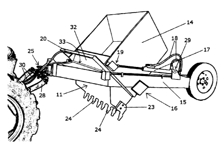
The figures l and 2 embodiment is made up of a bucket 10, which has an open
front end
11, a floor (not shown), a back wall 12, a first side wall 13, a second side
wall 14, an attached
toothed scraping edge 23, which has a row of scraping teeth 24, an open frame
15 within which
the bucket 10 is pivotally attached as at 16, two lifting arms 17, one on each
side of the bucket
10, a bucket strengthening member 20, a front gate 21, and a means 25 by which
the frame 15
can be attached to a standard tractor three point hitch 28.
A bucket strengthening member of any type, including of the type shown at 20,
is not an
essential feature of the invention. However, it is a recommended feature,
especially when
designed and installed as at 20, because in addition to being a bucket
strengthening member, it
can have equipment mounted on it that allows the person using the invention to
determine the
5
CA 02505562 2005-04-11
degree of flatness of the ground. It may also be used for the mounting of
other equipment, as
determined by the person using the invention.
The lifting arms in the embodiments shown in figures 1 to 4 are hydraulic.
Each of the
lifting arms is attached to the bucket 10, as at 19, and also attached to the
frame 15, as at 29. The
lifting arms need not be hydraulic, they can be mechanical, or of any other
workable type;
however, it is recommended to use hydraulic lifting arms, as they are cost
effective and in most
cases the mini earth scraper will be used behind a modem tractor that comes
with a hydraulic
control unit, thereby giving the User a quick, effective, and very easy way to
power and control
the lifting arms. In operation the hydraulic control lines 18 of the lifting
arms would be
connected to the tractor's hydraulic control unit's lines 30 through suitable
couplings and
extension lines, as will be obvious to those skilled in the art to which the
invention pertains.
A toothed scraping edge like the one shown at 23 is recommended, however, a
flat
scraping edge, as shown at 26 in figure 3 may also be used. Other scraping
edges, as will be
obvious to those skilled in the art, may also be used. Even when the bucket
and/or frame is made
out of a suitable plastic, suitable PVC, or other suitable material, it is
recommended that the
scraping edge be made out of metal. An advantage of an attachable (and
therefore removable)
scraping edge as shown at 23, is that it is the scrapping edge which is most
likely to become
damaged, broken or worn out, therefore if it is easily removable it can be
more easily and less
expensively repaired or replaced.
The wheels 27 can be attached at the back of frame 15 in different ways, as
shown in
figures l and 3; how the wheels are attached at the back of the frame, is not
relevant, as long as
they serve the purpose of allowing the frame, and bucket, when it is fully
loaded, to be pulled
behind the desired pulling vehicle. The number of wheels and the size and type
of wheels is also
6
CA 02505562 2005-04-11
not relevant to the invention, as long as they serve the purpose of allowing
the frame, and bucket,
when it is fully loaded, to be pulled behind the desired pulling vehicle.
The preferred embodiment of the invention shown in figures l and 2 also has a
front gate
21, which is not fixed to the bucket. The front gate 21 is hinged, by hinges
31, to the front of the
frame 15. In addition, the front gate 21 has rotateable cylindrical sleeves
22, which can roll up
and down along a channel (not shown) in the top edges of side walls 13 and 14.
In operation, as
the front of frame 15 is moved up, relative to the bottom of the bucket, the
bottom of front gate
21, which is hinged to the front of frame 15, will move up with the front of
frame 15, and the top
of front gate 21, by means of the rotateable cylindrical sleeves 22, will move
towards the back
wall 12, of the bucket, thereby uncovering more of the open front end 11 of
the bucket.
Another preferred embodiment of the invention, shown in figure 4, has a front
gate 32,
which is fixedly and rigidly attached to the front of frame 15. In operation,
as the front of frame
is moved up, relative to the bottom of the bucket, the front gate 32, which is
fixedly and
rigidly attached to frame 15, will move up with the front of frame 15, and the
top of front gate
15 32, because gate 32 is rigidly attached to the front of frame 1 S, will
maintain the same position
relative to the front of frame 15. Consequently, as the bottom front of bucket
10 and the front of
frame 15 are moved farther apart, the front gate 32 will also move farther
apart from the bottom
front of bucket 10, thereby uncovering more of the open front end 11 of the
bucket.
The front gate is not an essential feature of the invention, however, it is a
recommended
feature. How the gate acts when it is opened or closed is also not relevant,
as long as the gate
can remain opened sui~ciently to allow for the scrapped up bumps, rocks, and
other protrusions
to be scooped up in the bucket as it is pulled forward, when the invention is
being used for earth
7
i ,
CA 02505562 2005-04-11
scrapping; and as long as the gate can remain opened sufficiently for emptying
the bucket's load,
when the operator wants to dump out the bucket's load.
Figures 1, 2 and 4 show a preferred embodiment being used with a standard
modern
tractor. To attach the invention to the tractor, the person lifts the front of
the mini earth scraper's
frame and using means 25 attaches the frame to a standard three point hitch 28
of the tractor.
The person then connects the hydraulic lines 18 of the lifting arms 17 to the
tractor's hydraulic
control unit's lines 30. The person then gets in the tractor and using the
tractor's three point hitch
controls, easily adjusts the height of the frame as often and as exactingly as
desired, and using
the tractor's hydraulic control unit easily adjusts the angle of the bucket
relative to the frame, as
often and as exactingly as desired. The User can then as often as desired
readjust the height of
the frame and the angle of the bucket relative to the frame, to achieve any
desired level of
closeness and pressure of earth scraping, by using the tractor's three point
hitch controls and
hydraulic control unit's controls, which in a standard modern tractor are
quickly and easily
accessible to the driver while he is driving. With the bucket in scraping
position, driving forward
the vehicle that is pulling the mini earth scraper causes the mini earth
scraper to scrap the earth's
surface, removing bumps and protrusions, which are then scooped up by the
bucket as it moves
forward. When the bucket is filled to the desired level, the driver adjusts
the height of the frame
and the angle of the bucket so that its load will not spill out. The driver
then drives to the
dumping area, and adjusts the bucket frame's height, and the bucket's angle to
dump its load.
Variations to the invention can be made, as shown by way of example in the
embodiments
illustrated in the figures and as explained in the disclosure; in addition,
other variations will be
obvious to those skilled in the art, and they are covered by the appended
claims, as they are
within the scope of the invention.
8