Note: Descriptions are shown in the official language in which they were submitted.
CA 02505794 2010-06-21
An Adjustable Length Tap Assembly For Drilling A Hole Into A Bone
Field of the Invention
The present invention is directed to a self-drilling tap and its method for
use in
orthopedic procedures to treat bone, and in particular to a device and method
for drilling
and tapping holes in bone to accommodate screws used in cranio-facial,
mandible, pelvic
and other orthopedic procedures.
Background of the Invention
Drilling in bones, particularly bones of the face and had, requires accurate
and
reliable control over the penetration depth. For instance, over drilling and
tapping a bore
may damage the brain or other underlying soft tissue. To reduce this risk,
self-drilling taps
for use in crane-facial procedures generally have a fixed depth. There exists
a need for a
selfdrilling tap having an adjustable length, which may accurately and
reliably replace
several taps of various fixed lengths.
Summary of the Invention
The present invention is directed to a tap assembly which may be adjusted by a
user
to drill and tap holes in bone in order to accommodate screws of various
lengths. The
adjustable length tap may comprise a shaft, a stop collar and a locking
collar, which
cooperate to expose and set an effective length of cutting threads located on
the tip of the
shaft.
The shaft preferably has a longitudinal axis, a proximal end, and a distal end
with
cutting threads for drilling and tapping holes in bone. The adjustable length
tap assembly
may also include a stop collar having proximal and distal ends. ,The distal
and of the stop
collar is preferably configured and dimensioned to provide a stop for the self
drilling tap.
The stop collar preferably is configured and dimensioned to be translatable
along the
longitudinal axis of the shaft The shaft preferably includes length indicator
marks, the
length indicator marks being configured and dimensioned to allow for a
controlled setting of
the effective length of the adjustable length tap assembly. Each length
indicator mark is
preferably configured and dimensioned to correspond with one effective length.
In addition,
each length indicator mark is preferably configured and dimensioned to be
visibly aligned
with the proximal end of the stop collar, when the effective length is set. In
an exemplary
embodiment, each length indicator mark is selectively disposed on the shaft,
and each
-1-
CA 02505794 2005-05-11
WO 2004/043270 PCT/US2003/036619
length indicator mark is visibly identified by indicia. The shaft is
preferably: made from bio-
compatible materials and may be made from non-magnetic materials.
The stop collar has a body having an inner surface and an outer surface. A
portion
of the inner surface is preferably configured and dimensioned to engage with
the shaft in at
least one predetermined location. The stop collar preferably has one or more
fingers, and the
shaft preferably has one or more grooves. In addition, the one or more fingers
may have
inner and outer surfaces and at least one projection or nub formed on the
inner surface. The
projection preferably is configured and dimensioned to interact with the
grooves to prevent
translational movement of the stop collar along the longitudinal axis of the
shaft. The one
or more fingers preferably is formed by at least two slots. Each of the two
slots preferably
extend from the outer surface of the stop collar to the inner surface of the
stop collar.
Preferably, the stop collar has at least two fingers, the fingers being
substantially identical
and arranged in a substantially symmetrical configuration about a central axis
of the stop
collar.
In an illustrative embodiment, the at least one projection on the stop collar
has a
mid-point, and the at least one groove on the'shaft has a mid-point. A first
distance
measured from the mid-point of the at least one projection to the proximal end
of the stop
collar preferably is related to a second distance measured from the mid-point
of the at least
one groove to a corresponding length indicator mark on the shaft. The first
distance
preferably is substantially equal to the second distance. The grooves
preferably extend
continuously about the shaft, and the grooves preferably are oriented
substantially
perpendicular to the longitudinal axis of the shaft. In an exemplary
embodiment, the
grooves are substantially equidistant from one another. The grooves may also
be
substantially identical in size and shape.
The adjustable length tap assembly also comprises a locking collar. The
locking
collar preferably is configured and dimensioned to be received over at least a
portion of the
stop collar. The locking collar is preferably configured and dimensioned to
engage with the
stop collar to set the effective length of the cutting threads, and preferably
to prevent
movement of the stop collar along the longitudinal axis of the shaft. The
locking collar,
also, is preferably configured and dimensioned to bear against a structure on
the outer
surface of the one or more fingers to releasably engage the at least one nub
with a groove on
the shaft. The locking collar preferably comprises a tubular member having a
bore, and the
proximal end of the locking collar preferably is capable of translating over
the proximal end
of the stop collar. In an exemplary embodiment, at least a part of the locking
collar is
-2-
CA 02505794 2005-05-11
WO 2004/043270 PCT/US2003/036619
transparent, and the locking collar preferably is formed from a medical grade
poly-carbonate.
In use, the locking collar and the stop collar preferably engage or mate with
each
other in at least two configurations, a first configuration which allows
transnational
movement of the stop collar and locking collar together along the shaft, and a
second
configuration that prevents translational movement of the stop collar along
the longitudinal
axis of the shaft. The stop collar and locking collar, generally, are free to
rotate about the
shaft when the stop collar and locking collar engage in the second
configuration.
The present invention is also directed to a surgical kit for drilling and
tapping holes
in bone. The kit preferably comprises one or more shafts each having a
longitudinal axis, a
proximal end and a distal end. At least a portion of each shaft should have
cutting threads
for drilling and tapping bores in bone. The kit may also include a stop collar
having
proximal and distal ends, which preferably is configured and dimensioned to be
translatable
along the longitudinal axis of each of the shafts. The stop collar preferably
has a body
having an inner surface and an outer surface, at least a portion of the inner
surface being
configured and dimensioned to engage with the at least one shaft in at least
one
predetermined location. Additionally, the kit may further include include a
locking collar
comprising a member configured and dimensioned to be received over at least a
portion of
the stop collar. The locking collar preferably is configured and dimensioned
to engage or
mate with the stop collar to set at least one effective length for the cutting
threads and
preferably to prevent movement of the stop collar along the longitudinal axis
of the at least
one shaft.
The invention also relates to a method for drilling and tapping a bore in
bone. The
method preferably comprises selecting a bone fastening element having a screw
thread, and
selecting a self-drilling tap having a longitudinal axis and cutting threads.
Preferably, the
cutting threads are located on the distal end of the self-drilling tap and are
adapted to create
and tap a bore in bone for receiving the selected screw thread. The method
preferably
includes mounting a stop collar on the tap, positioning a locking collar on
the tap, passing at
least a part of the locking collar over the proximal end of the stop collar,
and joining the
stop collar with the locking collar. The method preferably comprises
positioning the stop
collar in at least one predetermined location which may cover at least a part
of the cutting
threads, verifying the location of the stop collar by visually inspecting the
location of the
proximal end of the stop collar relative to the self-drilling tap, and locking
relative
movement of the self-drilling tap, stop collar, and locking collar along the
longitudinal axis.
The method preferably includes placing the cutting threads on bone, rotating
the self-
drilling tap to advance the cutting threads into bone, forming a tapped bore
in bone,
-3-
CA 02505794 2005-05-11
WO 2004/043270 PCT/US2003/036619
contacting the stop collar against a surface to block advancement of the self-
drilling tap, and
removing the self-drilling tap from the bore. The method may further include
advancing the
screw thread into the bore to fix the bone fastening element in bone.
Brief Description of the Drawings
Preferred features of the present invention are disclosed in the accompanying
drawings, wherein similar reference characters denote similar elements
throughout the
several views, and wherein:
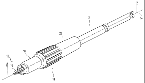
FIG. 1 shows a perspective view of an exemplary embodiment of the adjustable
length tap assembly.
FIG. 2 shows a partial cross-sectional view along line 2--2 of FIG. 1;
FIG. 3 shows a plan view of the shaft of the tap assembly of FIG. 2 ;
FIG. 4 shows a partial plan view of the reverse side of the of shaft of FIG.
3;
FIG. 5 shows an enlarged view of grooves and markings on the shaft of FIG. 3;
FIG. 6 shows a perspective view of the stop collar of the tap assembly of FIG.
1;
FIG. 7 shows a cross-sectional view along line 7--7 of FIG. 6;
FIG. 8 shows an enlarged plan view of a slot of the stop collar of FIG. 6;
FIG. 9 shows an enlarged view of a nub and seating projection on the stop
collar of
FIG. 6;
FIG. 10 shows a front elevation of the locking collar shown in FIG. 1;
FIG. 11 shows a cross-sectional view along line 11--11 of FIG. 10;
FIG. 12 shows a partial cross-sectional view along the longitudinal axis of
another
embodiment of the tap assembly of FIG 1;
FIG. 13 shows a cross-sectional view of the locking collar along the
longitudinal
axis of the tap assembly of FIG. 12;
FIG. 14 is a perspective view of an exemplary collection of instruments, which
in
use, may form an adjustable length tap assembly of FIG. 1; and
FIG. 15 is a plan view of an illustrative kit housing the collection of
instruments of
FIG. 14.
Detailed Description of the Embodiments
In the description that follows, any reference to either orientation or
direction is
intended primarily for the convenience of description and is not intended in
any way to limit
the scope of the present invention thereto.
-4-
CA 02505794 2005-05-11
WO 2004/043270 PCT/US2003/036619
FIG. 1 shows an assembly 10 for use in drilling and tapping holes in bone. The
assembly 10 comprises a self-drilling tap 12 having a longitudinal axis 14, a
stop collar 18,
and a locking collar 20. The self-drilling tap 12 may have a distal end 13
with cutting
threads 16 adapted to drill and tap holes in bone. The stop collar 18 and
locking collar 20
may be moved along the self-drilling tap 12 to expose a portion of the cutting
threads 16.
The relative position of stop collar 18 and locking collar 20 may be fixed
along the
longitudinal axis 14 of the self-drilling tap 12. The stop collar 18 and the
locking collar 20
may be free to rotate about the longitudinal axis 14 of the self-drilling tap,
even though
translational movement along the longitudinal axis 14 is prevented. The
assembly 10 may
be used with other instruments such as a handle and guide plate (not shown) to
drill and tap
holes in bone. Detachable handles, guide plates, and drills are representative
of the
instruments and other devices that may be used in conjunction with the
adjustable length tap
assembly. These instruments, however, may not always be required or may be
replaced by
different devices that perform similar, additional, or different functions.
_ FIG. 2 shows a cut away view of the adjustable length tap assembly. The stop
collar
18 and the locking collar 20 are shown in cross-section, and the shaft 22 is
shown in plan
view. As shown in FIG. 2, the self-drilling tap 12 includes a shaft 22 having
a tip or distal
end 13 with cutting threads 16. The tap 12 further comprises a plurality of
circumferential
grooves 24, indica 26, such as for example lines, for marking the effective
length 28 of the
exposed portion of the cutting threads 16, and a coupling element 30 for
connecting the self-
drilling tap 12 to a handle or a drill (not shown) at the proximal end 31
thereof.
The maximum outer diameter 32 of the cutting threads 16 and the length 34 of
the
tip 13, which contains the cutting threads, may be fixed. The dimensions of
the tip 13, for
any particular tap 12, may be based on the size and length of the screw for to
be inserted in
the bore. The dimensions of the tip 13 may further be adapted to accommodate
the
thickness of a guide plate. For instance, a special screw may be. developed
for use in a
pelvic procedure, for example, and the dimensions of the tip 13 of the self-
drilling tap 12
may be designed to accommodate that screw. For example, one screw type may
have an
outer diameter of 1.5 mm and a length of 3 mm, and the dimension of the tip 13
maybe
configured and dimensioned to create a tapped bore that is adapted for screws
of that type.
Other non-limiting examples of screws, for which the self-drilling tap 12
maybe
dimensioned, include screws having an outer diameter from about 2.0 mm to
about 4.0 mm
and having a length from about 3.0 mm to about 8.0 mm. As one skilled in the
art would
readily appreciate, a self-drilling tap may also be developed for larger or
smaller screws.
-5-
CA 02505794 2005-05-11
WO 2004/043270 PCT/US2003/036619
The cutting threads 16 may be particularly adapted to cut and remove bone
without
damaging adjacent tissue. The threads may include sharp cutting flutes 36 and
one or more
straight flutes 38 for removing bone chips and cuttings from the bore. For
example, two
straight flutes aligned 180 from each other may be disposed on the tip. One
of ordinary
skill in the art would readily appreciate that the number and configuration of
cutting flutes
36 and straight flutes 38 may be widely varied, or in addition to or
alternatively a wide
variety of other configurations and combinations may be used.
The shaft 22 of the tap 12, preferably, may have an outer diameter 40 that is
operably configured and dimensioned to slidably receive the stop collar 18 and
the locking
collar 20. A set of taps which may be adapted for screws having differing
predetermined
diameters and lengths, preferably may each have a shaft 22 of same diameter
40. In an
exemplary embodiment, the outer diameter 40 of the shaft 22 may be about 3.0
mm. As one
skilled in the art would readily appreciate, a set of self-drilling taps
having different tip
configurations may be supplied as a kit for use with one stop collar 18 and
one locking
collar 20. More than one stop collar 18 and more than one locking collar may
also be
supplied in the kit. For example, a set of taps 12 having a different outer
diameter may be
supplied which would be used with different stop and locking collar
combinations.
Referring to FIGS. 3-5, the shaft 22 may further comprise two or more grooves
24.
The grooves 24 may be spaced from the tip 13 on the middle portion of the tap
12. Each
groove 24 may or may not extend continuously about the shaft 22. In an
illustrative
embodiment of a self-drilling tap 12 there may be six grooves 24 spaced
equidistant from
one another and oriented perpendicular to the longitudinal axis of the shaft
22. As shown in
FIG. 5, the radius 42 (i.e, the distance equal to one-half the groove width
44) of each groove
24 preferably may be substantially constant. In addition, each groove
preferably may have
substantially the same radius 42. Similarly, the diameter 46 of the grooves 24
may vary, but
in a preferred embodiment are the same. The radius 42 and diameter 46 of each
groove 24
may be operably configured and dimensioned to cooperate with at least one
detent or nub 48
on the stop collar 18, as shown in FIG. 2. Engagement of a nub or projection
48 with a
groove 24 may be used to set the position of the stop collar along the length
of the shaft 22
and thus set the penetration or effective length 28 of the adjustable tap
assembly 10. As
described in further detail below, a user may selectively press the nubs of
the stop collar 18
into a groove 24 on the shaft to lock the penetration or effective length 28
of the adjustable
tap assembly.
As shown in FIG. 5, a tap 12 having a shaft 22, for example, with an outer
diameter
40 of about 3.0 mm may have grooves 24 having a diameter 46 of about 2.6 mm
and a
-6-
CA 02505794 2005-05-11
WO 2004/043270 PCT/US2003/036619
radius 42 of about 0.3 mm. Each groove 24 maybe spaced one from another at a
fixed
interval, for example, 1.0 mm on center. As one skilled in the art would
readily appreciate,
other groove configurations may be desirable. In general, however, a set of
self-drilling taps
adapted for screws of different diameters, as previously described,'may have
substantially
identical grooves and groove patterns so as to provide the user of the tool
with a uniform
feel when setting the penetration or effective length 28 of the adjustable tap
assembly 10. A
standard feel for setting the effective length 28 of the adjustable tap
assembly 10 may
promote ease, reliability, and accuracy in the selection of a desired
effective tap length 28
during a surgical procedure.
Indica 26 or length indicators maybe marked on the shaft 22 perpendicular to
the
longitudinal axis 14 of the self-drilling tap 12. In general, one length
indicator 26 may be
marked on the shaft 22 for each groove 24. Each length indicator 26 may
indicate the
length of the screw for which a bore is to be drilled. Alternatively, the
length indicator 26
may correspond to some other designation for a particular screw type. In
general, the
distance between the mid-point of one groove 24 and a corresponding length
indicator 26
may correspond with the dimensions of the stop collar 18 to allow for the
controlled and
accurate setting of a predetermined tap length 28. For example, the distance
52 between the
mid-point of a groove 24 and a corresponding length indicator 26, may be the
same length
as the distance 73, shown in FIG. 7, which is measured between the mid-point
of the nub 48
and the end 54 of the stop collar.
Referring back to FIGS. 2-5, length indicators 26 may be selectively marked on
the
shaft 22. For instance, the length indicators for screws having odd number
designations
may be marked on one side of the shaft, and length indicators for screws
having even
number designations may be marked on the other side of the shaft. Such a
marking pattern
may facilitate the selection of a desired effective length 28 by making it
easier to identify,
select, and confirm the adjustment. Moreover, each length indicator 26 may be
identified
by indica 56 which uniquely signify each possible tap length 28 selection. For
instance, the
indica 56 may comprise numerals which relate to the length or type of screw
for which a
bore is to be drilled and tapped. In an illustrative configuration, the indica
56 may be
numerals which are bisected by the associated length indicators 26. This
configuration may
provide for larger numerals and clearer identification of the associated
length indicator.
Markings 26, 56 may be laser etched into the shaft.
The self-drilling tap 12 may be adapted for use with an integrally formed
handle (not
shown). Alternatively, the proximal end of the self-drilling tap 31 may be
adapted for
connection to a removable handle or drill (not shown). For instance, the self-
drilling tap 12
-7-
CA 02505794 2005-05-11
WO 2004/043270 PCT/US2003/036619
may have a hex coupling for connecting to a handle for use as a manually
operated
instrument. The tap 12 might also be adapted for quick coupling to a drill. In
general, the
tap may be made from materials which are bio-compatible and possess relatively
high
mechanical durability. For example, the tap may be integrally formed from a
blank made
from stainless steel. In a preferred embodiment, the tap may be made from 440
A stainless
steel. The tap may also be made from non-magnetic materials so that it may be
suitable for
use with an MRI system. The tap may also be radiolucent, or portions may be
radiolucent.
FIG. 6 shows a perspective view of the stop collar of FIG. 1. As previously
described, the stop collar 18 is operably configured and dimensioned to
cooperate with the
shaft 22 and locking collar 20 to set and fix the penetration or effective
length 28 of the
adjustable length tap assembly 10. The stop collar shown in FIG. 6 has a nose
58 at the
distal end 60, a fore-collar 62 adjacent the nose 58, an abutment ring 64,
connecting
elements 66 for coupling with the locking collar 20, and a plurality of
fingers 68 for
engaging with the shaft 20.
The nose 58 may be configured and dimensioned to provide a secure stop for the
self-drilling tap 13 and may have an outer dimension close to the dimensions
of the shaft to
reduce visual obstruction of the tip 13 when the adjustable length tap
assembly 10 is
positioned for drilling. The outer dimension of the stop collar may then flare
outward
gradually to a second or intermediate outer-dimension at the fore-collar 62 to
provide a
surface which maybe readily gripped and manipulated by a user. Thus, the
profile of nose
58 and fore-collar 62 may be configured and dimensioned to reduce the
likelihood of
incorrect seating of the adjustable length tap assembly 10 on a drill plate
and/or bone.
The fore-collar 62 may further include a transition to a portion having a
larger outer
dimension which may form an abutment ring 64. The abutment ring 64 may be
operably
configured and dimensioned to provide a stop 70 for the locking collar 20,
which may be
connected to the stop collar 18 by connecting elements 66 located near the
abutment ring
64. In FIG. 6, the connecting elements 66 comprise external threads which are
disposed
about the central portion of the stop collar 18 between the abutment ring 64
and a plurality
of fingers 68. Coupling elements other than threads may be used to couple the
locking
collar 20 with the stop collar 18.
The fingers 68 assist in fixing the position of the stop collar and may each
generally
comprise an elongated member, that is formed by slots 72 in a thin wall
section of the stop
collar 18. The fingers 68 are configured and dimensioned to flex. In FIG. 6,
the stop collar
18 has four fingers 68. As one of skill in the art might appreciate, a stop
collar 18 having a
configuration with less or more fingers 68 might also be used. For example, a
stop collar
-8-
CA 02505794 2005-05-11
WO 2004/043270 PCT/US2003/036619
having three fingers defined by three slots may be used, or a stop collar with
five fingers
and having five slots may be used. The fingers 68 may be substantially
identical in
construction or they may differ one from another. Similarly, the fingers 68
may be disposed
in a substantially symmetrical configuration or they may be disposed about the
stop collar in
some other fashion. For instance, in the embodiment shown in FIGS. 6-9, the
stop collar 18
comprises four substantially identical fingers 68 disposed in a generally
symmetrical pattern
about the proximal end 74 of the stop collar 18.
As shown in FIGS. 7 and 9, the inner surface 78 of the fingers 68 maybe smooth
and may be configured and dimensioned to bear upon and slide along the shaft
22 of the
self-drilling tap 12. The fingers 68 of the stop collar 18 may also be
operably configured
and dimensioned to selectively engage and disengage with the grooves 24 of the
tap 12. For
example, this maybe accomplished by a projection, structure or nub 48 located
on the inner
surface 78 of each finger 68.
The outer surface 76 of each finger 68 may be configured and dimensioned to
slidably receive the locking collar 20 over the outer surface 76. The outer
surfaces 76 of the
fingers 68 also may be configured and dimensioned to bear against the locking
collar 20.
This may be accomplished by a structure, as shown in FIGS. 8 and 9, such as a
raised area
or seat 80, located on the outer surface 76 of each finger 68. In general, as
the locking
collar 20 is advanced over the stop collar 18, the locking collar may press
against the seat 80
and drive the nub 48 into engagement with a groove 24 on the shaft 22 of the
self-drilling
tap 12. The nub 48, for example, may be substantially triangular or
trapezoidal in section.
The shape of the nub 48 may be designed to securely engage with the groove 24
when
locking the penetration or effective length 28 of the adjustable length tap
assembly 10. The
shape of nub may also be configured to facilitate disengagement of the nub 48
from a
groove 24 when unlocking or adjusting the effective length 28 of the
adjustable length tap
assembly 10.
Referring to FIG. 8, the number and geometry of the slots 72 may be configured
and
dimensioned to provide the fingers 68 with special properties. For instance, a
slot 72
comprising an enlarged rounded portion 82 at the base may be formed to provide
special
properties to the finger. The enlarged rounded portion 82 may provide
increased flexibility
while preventing stress concentrations and fatigue. Also, one or more slots 72
may be
adapted to provide increased resiliency or flex to the fingers 68, making it
easier to slide the
stop collar 18 along the shaft 22, as the nubs 48 engage and disengage with
the grooves 24.
The stop collar 18 may be formed from materials which are bio-compatible, and
which are capable of withstanding the required mechanical loading and
abrasion. For
-9-
CA 02505794 2010-06-21
example, the stop collar 18, preferably may be made from materials that are
durable and
will prevent shearing of the nubs. In addition, the stop collar may be made
from materials
which provide the fingers with added resiliency to movement yet will not
readily fatigue or
fail during use. In addition, the stop collar 18 preferably may be made from
materials which
will not fail when placed into abrasive contact with a drill guide plate
during use. Thus, for
example, the stop collar 18 preferably may be made from any 300 series
stainless steel.
Preferably, 316 stainless steel may be used to form the stop collar 18. Other
non-limiting
examples of materials from which the stop collar may be formed in include
titanium and
titanium-alloys. The stop collar 18 might also be formed from materials which
are non
magnetic in order to provide a tap assembly 18 which is suitable for use with
an MRI
system. The stop collar may also be radiolucent, or portions may be
radiolucent.
Referring to FIGS. 10 and 11, the locking collar 20 generally comprises a
tubular
member having a bore 86, which is configured and adapted to engage or mate
with the stop
collar 18. The locking collar 20 may control the movement of the tap assembly.
The cross-
section 10' of the locking collar 20 taken in a direction perpendicular to the
longitudinal axis 14,
of the locking collar may be substantially uniform. Alternatively, the locking
collar 20 may
have a cross section that varies. For example, the shape of the exterior
surface 84 may be
constant and the shape and diameter of the interior bore 86 may vary along the
length of the
locking collar. In another example, the shape of the exterior surface 84 may
vary and the
bore 86 may remain substantially unchanged along the length of the locking
collar 20. In
the embodiment shown in FIGS. 10 and 11, the locking collar is a generally
hollow
cylinder.
In general, the bore 86 of the locking collar 20 may be configured and
dimensioned
to slide along the tap 12 as well as over the fingers 68 of the stop collar
18. The cross-
section of the bore 86 may be circular, polygonal or some other shape. In
addition, the
dimensions of the bore 86 may vary, and part of the bore 86 may be adapted to
connect with
the stop collar 18. For example, the distal end 88 of the bore 86 may comprise
internal
screw threads 90. Additionally, the bore 86 of the locking collar 20 may
comprise sections
having different dimensions. In particular, the locking collar may have a bore
86
comprising multiple sections of progressively smaller dimension. For instance,
the
dimensions of the bore may be greater at the distal end 88 than at the
proximal end 92 of the
locking collar 20, such that the progressive change in dimensions of the bore
86 presses the
fingers 68 of the stop collar 18 more firmly into the grooves 24 of the shaft
22 when the
locking collar 20 and stop collar 18 are coupled and tightened.
-10-
CA 02505794 2005-05-11
WO 2004/043270 PCT/US2003/036619
The exterior surfaces 84 of the locking collar 20 may also facilitate quick,
reliable
and accurate adjustment of the exposed tap length 28. In the embodiment of
FIGS. 10 and
11, the dimension of the exterior surface 84 tapers gradually from the distal
end to the
proximal end. The locking collar 20 may be thicker at the distal end 88 to
accommodate
internal coupling elements 90 (for example, internal screw threads) which are
adapted to
engage or mate with connecting elements 66 (for example, external screw
threads) on the
stop collar 18. The locking collar 20 also may be thicker in the distal end 88
to provide a
comfortable gripping section 94 so that the locking collar 20 may be reliably
held and
manipulated.
The exterior surface 84 of the locking collar 20 may further comprise raised
areas 96
to enhance the grip and tactile feel of the locking collar 20. In addition,
the raised areas 96
may promote the ease and reliability of setting and locking the length 28 of
the tap
assembly. In FIGS. 10 and 11, these raised areas 96 are in the form of
longitudinal ridges
that are radially disposed about the outer surface 84 of the locking collar.
Other grip
enhancing configurations on the exterior surface 84 might also be envisioned
by one of
ordinary skill in the art, such as for example, circumferential raised areas
or ridges, or
combinations of longitudinal and circumferential ridges, or other surface
texturing.
The proximal end 92 of the locking collar 20 may have a thinner wall section
than at
the distal end 88 to enhance visibility through the locking collar 20 when
looking at
markings on the shaft 22. A thinner wall section may also enhance visibility
through these
areas of the locking collar 20. A relatively thin wall section at the distal
end 88 may also
enhance visual clarity along the shaft 22 and through openings or windows that
maybe
formed in the locking collar 20. For instance, the proximal end 92 (i.e the
finger tips) of the
locking collar 20 may align with the selected length indicator 26 for a
desired tap length 28.
In another example, the selected tap length indicator 26 and indica 56 may be
visible
through an opening or window in an opaque locking collar 20.
In FIGS. 10 and 11, the proximal end 92 of the locking collar 20 may comprise
a
clear material, which may be substantially transparent. The visibility
provided by such a
material may allow a user to see directly through the locking collar 20 and
easily view the
length indicators 26, indica 56, and the proximal end 92 of the stop collar 18
to visually
determine the effective length 28 of the adjustable-length tap assembly. The
clear material
may or may not have a tint. One clear material from which the locking collar
may be made
is plastic. In particular, the locking collar 20 may be configured and
dimensioned to be
fabricated as a molded piece. A locking collar 20 formed from plastic may have
connecting
elements 90 (for example, threads) for connecting to the stop collar 18 which
maybe made
-11-
CA 02505794 2005-05-11
WO 2004/043270 PCT/US2003/036619
from other materials. In a preferred embodiment, the molded locking collar 20
may be
made from a medical grade poly-carbonate. For example, the locking collar may
be formed
from "MAKROLON."TM In general, plastic materials that may be used for forming
the
locking collar 20 should be able to withstand gamma-sterilization during
packaging. The
locking collar 20 may also be made from other bio-compatible materials,
including the same
materials described above in connection with the shaft and stop collar.
Referring to FIGS. 12 and 13, in another embodiment of the adjustable length
tap
assembly 98, the locking collar 99 may be specially configured and dimensioned
to be
formed from a metal-alloy such as 316 stainless steel. As shown in FIG. 13,
the locking
collar 99 may comprise a cylinder having a bore 100 of varying dimension,
which extends
from the distal end 101 to the proximal end 102. As shown in FIG. 12, the
locking collar 99
may be capable of sliding completely over the proximal end 103 of the stop
collar 104,
when coupled to the stop collar, thereby providing an unobstructed view of the
length
indicators. Thus, the locking collar 99 may or may not have windows or slots
to allow a
user to read the setting of effective length 28 of the adjustable length tap
assembly 98.
FIG. 14 shows an exemplary collection of instruments 104, which may be
included
in a pre-packaged surgical kit 106 (shown in FIG. 15) for forming an
adjustable length, tap
assembly 12 that may be used to drill and tap bores in bone. The instruments
104 preferably
may include a stop collar 18, a locking collar 20, and more than one tap 12.
The collection
of instruments 104 preferably may also include a handle (not shown) for
releasably securing
to each tap 12, so that a user may manually drill and tap bores in bone. In
the illustrative
embodiment shown in FIG. 14, three taps 12 are included in the collection 104.
The taps 12
preferably may be used interchangeably with the stop collar 18 and the locking
collar 20.
The taps 12 preferably may also have identical shaft 22 and groove
configurations 24. The
taps 12 may further have cutting threads 16 that are adapted for screws of a
similar type but
of different diameter. Alternatively, the taps may have cutting threads 16 of
substantially
identical size and shape, or the cutting threads 16 adapted for different
types of screws.
It should be appreciated that a wide variety of various instruments may be
contained in the
kit 106. For example, a first kit may package a collection of instruments
adapted for a
particular mandible procedure, a second kit can package a collection of
instruments adapted
for a particular pelvic procedure, and a third kit may package a collection of
instruments for
a particular orthopedic procedure. FIGS. 14 and 15 illustrate one of many
different possible
embodiments for the instrument collection 104 and kit housing 106.
Referring to FIG. 15, in the illustrated embodiment, the kit 106 includes an
interior
tray 108 made, e.g., from die cut cardboard, plastic sheet, or thermo-formed
-12-
CA 02505794 2010-06-21
plastic material. The tray 108 may include spaced apart tabs or the like (not
shown), which
may hold the various instruments 104 in a secure position during sterilization
and storage
prior to use. When packaged as. a sterile assembly, the kit 106 may include an
inner wrap
110, which is peripherally sealed by heat or the like, to enclose the tray 108
from contact
with the outside environment. One end of the inner wrap may include a
conventional
peal-away seal 112, to provide quick access to the tray 108 at the instant of
use, which
preferably occurs in a sterile environment, such as within an operating room.
When
packaged as a sterile assembly, the kit 106 may also include an outer wrap
114, which is
also peripherally sealed by heat or the like, to enclosed the inner wrap 110.
One end of the
outer wrap may also include a conventional peal-away seal 116, to provide
access to the
inner wrap 110 and its contents. The outer wrap 114 can be removed from the
inner wrap in
anticipation of imminent use, without compromising sterility of the contents
of the kit 106.
Each inner and outer wrap 110 and 114 may include a peripherally sealed top
sheet
and bottom sheet (not shown). In the illustrated embodiment, the top sheet
preferably may be made of transparent plastic film, like polyethylene or
MYLAR.TM
material, to allow visual identification of the contents of the kit 106. The
bottom sheet may
be made from a material that is permeable to ETO sterilization gas, such as,
for example,
TYVEKT" plastic material. The kit 106 may also include in the tray 108
directions 120 for
using the contents of the kit 106 to carry out a desired procedure. An
exemplary procedure
which the directions 120 can describe will be explained later. When packaged
as a sterile
assembly, the directions 120 may also include a statement, for example, "For
Single Patient
Use Only" (or comparable language) to affirmatively caution against reuse of
the contents of
the kit 106 whose performance characteristics and efficacy may degrade after
use. The
adjustable length tap assembly 20, for these reasons, may be used but for a
single surgical
procedure and then discarded. The directions 120 may also affirmatively
instruct against
resterilization of a portion or all of the contents of the kit 106, and also
may instruct the
physician to dispose of at least these contents of the kit 106 upon use in
accordance with
applicable biological waste procedures. The presence of the collection of
instruments 104
packaged in the sterile kit 106 may verify to the physician that the contents
are sterile and
have not been subjected to prior use. The physician may thereby be assured
that the
instruments 104 meet established performance and sterility specifications.
In use, the locking collar 20 slips over the stop collar 18 and tap 12 and
when
tightened to the stop collar 18, locks the assembly 10. The locking may be
accomplished by
nubs 48 on the fingers 68 of the stop collar 18 being driven into grooves 24
on the shaft 22.
The proximal edge of the fingers (i.e., the finger tips) 88 may align with the
length indicator
-13-
CA 02505794 2005-05-11
WO 2004/043270 PCT/US2003/036619
26 on the tap shaft 12 that corresponds with the groove 24 the nubs 48 engage.
Once the
stop collar 18 and the locking collar 20 are coupled together, the degree of
engagement
between the nubs 48 and the locking grooves 20 may be controlled. The degree
of
engagement between the grooves 24 and the nubs 48 may vary by design from a
firm
engagement to loose engagement. When loosely engaged the stop collar 18 and
the locking
collar 20 may be moved in unison along the shaft 22 in a ratchet like fashion.
To promote a
secure connection between the stop collar 18, the locking collar 20, and the
shaft 22, the
fingers 68 of the stop collarl 8 have a raised area 80 on the outer surface 76
to cause the nub
48 on the inner surface 78 to be pushed firmly into engagement with the groove
24. The
stop collar 18 and locking collar 20 preferably are capable of resisting,
without axial
movement, an axial force of at least about 300 N, when the adjustable length
tap assembly
is locked.
The adjustable length tap assembly 10 is directed toward a method for drilling
and
tapping holes in bone. Initially, a user selects a tap 12 for preparing a bore
which is adapted
for a particular screw configuration. The selection may be based, for
instance, on the screw
diameter, or the part number of the screw. A stop collar 18 then may be
mounted about the
tap 12 along a shaft 22, with the proximal ends 54 of the fingers 68 pointing
toward the
proximal end 31 of the shaft 22. A locking collar 20 may then be positioned on
the shaft 22
of the tap 12 so that it is capable of coupling with the stop collar 18. The
stop collar 18 and
the locking collar 22 are then joined together.
The tightness of the connection between the stop collar 18 and the locking
collar 20
may then be adjusted to provide a desired resistance to movement between the
stop collar-
locking collar combination and the tap 12. The position of the stop collar 18
may then be
adjusted to a desired tap length 28 setting by aligning the proximal ends 74
of the stop collar
with the desired length indicator 26. For example, the numeral 5 may designate
the
appropriate length indicator 26 for a particular screw with a length of 5 mm.
The
connection between the stop collar 18 and the locking collar 20 may then be
tightened to
secure the selected length 28 of the tap assembly. Alternatively, the position
of the stop
collar may be positioned to provide a desired tap length. The stop collar 18
may be
advanced to set the desired position and the locking collar then positioned on
the shaft,
coupled to the stop collar, and adjusted to lock the stop collar and locking
collar assembly
in place on the shaft.
The proximal end 31 of the self-drilling tap 12 may then be inserted in to a
drill (not
shown), such as a battery powered reversible drill. The tip 13 of the self-
drilling tap 12 may
be seated in a guide plate and placed into contact with bone. The drill may
then be used to
-14-
CA 02505794 2005-05-11
WO 2004/043270 PCT/US2003/036619
rotate the adjustable length tap assembly 10 to bore and tap a hole of
predeteimined
dimension into the bone. The maximum depth of the bore may be reached when the
nose
58 of the stop collar contacts the guide plate. The adjustable length tap
assembly 10 may
then be withdrawn from the bore and the guide plate, and a screw advanced and
secured in
the tapped bore.
The locking mechanism of the assembly 10 allows the stop collar 18 and locking
collar 20 to rotate with respect to the tap 12, particularly after the stop
collar 18 hits the drill
guide plate without affecting the previously adjusted length setting 28.
Because the nub 48
is firmly seated in the groove 24, the length of the tap 28 may not change,
however, the stop
collar 18 and locking collar 20 are free to rotate about the shaft 22. This
may facilitate
accuracy in the advancement of bores having a pre-selected depth. For
instance, if relative
rotation between the stop collar 20 and the shaft could change the length of
the exposed
cutting threads 28, each time the stop collar hits the drill guide plate the
resulting movement
between the shaft and the stop collar might potentially cause the tap 12 to
change length 28.
If the exposed length of the cutting threads 28 was unintentionally lengthened
the bore
might proceed undesirably through the bone and into adjacent tissue. By
contrast, if the
exposed length of the cutting threads 28 was decreased, a screw advancing into
untaped
bone might damage or crack the bone or in the case of resorbable screws,
damage may
occur to the screw.
The tap assembly may also provide useful tactile feed back to the user, due to
the
ratchet effect of the nubs 48 engaging and disengaging with the grooves 24 as
the stop collar
18 and locking collar 28 are moved along the shaft 22. A user may feel and
hear the
number of clicks as the nubs disengage and engage grooves as the stop collar
translates
along the shaft from a first known tap length setting to a desired second tap
length setting,
thereby increasing the speed of tap adjustments during a procedure. In
addition, the ratchet
effect of the locking mechanism may provide an additional check for assuring
the proper
length is selected as the user need not rely on a purely visual system to
select or check the
length adjustment of the tap assembly.
While the above adjustable length tap assembly has been described with
reference to
certain preferred embodiments, it should be kept in mind that the scope of the
present
invention is not limited to these embodiments. For instance, the adjustable
length tap
assembly may be modified, or extended to accommodate particular formulations
of
construction materials or fabrication techniques which may require different
connecting
elements. Similarly, the number and spacing of the grooves on the shaft may be
changed to
accommodate different screw lengths. Also, different materials and surface
coatings, or
-15-
CA 02505794 2005-05-11
WO 2004/043270 PCT/US2003/036619
outer layers of different materials may be applied to the adjustable length
tap -,assembly. In
addition, the embodiments above can be modified so that some features of one
embodiment
are used with the features of another embodiment. One skilled in the art may
adapt
variations of these preferred embodiments which, nevertheless, fall within the
spirit of the
present invention, whose scope is defined by the claims set forth below.
15
25
35
-16-