Language selection

Search

Patent 2505798 Summary

Third-party information liability

Some of the information on this Web page has been provided by external sources. The Government of Canada is not responsible for the accuracy, reliability or currency of the information supplied by external sources. Users wishing to rely upon this information should consult directly with the source of the information. Content provided by external sources is not subject to official languages, privacy and accessibility requirements.

Claims and Abstract availability

Any discrepancies in the text and image of the Claims and Abstract are due to differing posting times. Text of the Claims and Abstract are posted:

  • At the time the application is open to public inspection;
  • At the time of issue of the patent (grant).
(12) Patent: (11) CA 2505798
(54) English Title: PLUMBING SYSTEM TEST VALVE
(54) French Title: ROBINET D'ESSAI DE PLOMBERIE
Status: Granted
Bibliographic Data
(51) International Patent Classification (IPC):
  • F16L 55/105 (2006.01)
  • G01M 3/02 (2006.01)
(72) Inventors :
  • COSCARELLA, GABE (Canada)
(73) Owners :
  • COSCARELLA, GABE (Canada)
(71) Applicants :
  • COSCARELLA, GABE (Canada)
(74) Agent: WOODRUFF, NATHAN V.
(74) Associate agent:
(45) Issued: 2013-07-09
(22) Filed Date: 2005-04-27
(41) Open to Public Inspection: 2006-10-27
Examination requested: 2010-02-02
Availability of licence: N/A
(25) Language of filing: English

Patent Cooperation Treaty (PCT): No

(30) Application Priority Data: None

Abstracts

English Abstract

A plumbing system test valve, includes a valve body defining a first pipe connection, a second pipe connection, and an access opening, a flow channel extends between the first pipe connection and the second pipe connection and a valve seat. A removable valve member is provided which is adapted to engage the valve seat of the valve body to prevent liquid from flowing along the flow channel between the first pipe connection and the second pipe connection. The removable valve member is removable through the access opening. At least one fill port is provided which is adapted to facilitate filling the valve body with liquid on one side of the valve member.


French Abstract

Un robinet d'essai de plomberie comprend un corps de robinet qui définit un premier raccord de conduite, un second raccord de conduite et une ouverture d'accès. Un canal de débit s'étend entre le premier raccord de conduite, le second raccord de conduite et le siège de robinet. Un élément amovible de robinet est fourni, lequel est adapté pour s'engager avec le siège de robinet du corps de robinet, de sorte à prévenir l'écoulement du liquide le long du canal de débit entre le premier raccord de conduite et le second raccord de conduite. L'élément amovible de robinet peut se retirer par l'ouverture d'accès. Au moins un orifice de remplissage est présent, lequel est adapté pour permettre le remplissage du corps de robinet avec du liquide d'un côté de l'élément de robinet.

Claims

Note: Claims are shown in the official language in which they were submitted.


5

What is Claimed is:

1. A plumbing system test valve, comprising:
a valve body defining a first pipe connection, a second pipe connection, an
access
opening, a flow channel that extends between the first pipe connection and the
second pipe
connection and a valve seat;
a removable valve member adapted to engage the valve seat of the valve body to

prevent liquid from flowing along the flow channel between the first pipe
connection and the
second pipe connection, the removable valve member being removable through the
access
opening; and
at least one fill port adapted to facilitate filling the valve body with
liquid on one side
of the valve member, the at least one fill port being sheltered within the
access opening.
2. The plumbing system test valve as defined in Claim 1, wherein a first fill
port is
positioned on a first side the valve member and a second fill port is provided
on a second side
of the valve member.
3. A plumbing system test valve, comprising:
a valve body defining a first pipe connection, a second pipe connection, an
access
opening, a flow channel that extends between the first pipe connection and the
second pipe
connection and a valve seat;
a removable valve member adapted to engage the valve seat of the valve body to

prevent liquid from flowing along the flow channel between the first pipe
connection and the
second pipe connection, the removable valve member being removable through the
access
opening; and
a first fill port adapted to facilitate filling the valve body with liquid on
one side of the
valve member positioned on a first side the valve member;
a second fill port adapted to facilitate filling the valve body with liquid on
another side
of the valve member positioned on a second side of the valve member;
the first fill port and the second fill port being sheltered within the access
opening.

Description

Note: Descriptions are shown in the official language in which they were submitted.


CA 02505798 2005-04-27
1
TITLE OF THE INVENTION:
Plumbing System Test Valve
FIELD OF THE INVENTION
The present invention relates to a valve used to test plumbing systems.
BACKGROUND OF THE INVENTION
When testing plumbing systems, plugs are inserted at one end of a plumbing
line and
the plumbing line is filled with liquid either upstream or downstream of the
plug to test for
leaks. These types of test plugs are well known in the art, examples of which
can be found in
the following patents: US 2,373,242 (Glashow 1945); US 3,154,106 (Ver Nooy
1964); US
3,442,295 (Ver Nooy 1969); US 4,040,450 (Boundy 1977); US 6,062,262 (Tash
2000); US
6,289,935 (Tash 2001);
SUMMARY OF THE INVENTION
According to the present invention there is provided a plumbing system test
valve,
which includes a valve body defining a first pipe connection, a second pipe
connection, and
an access opening, a flow channel extends between the first pipe connection
and the second
pipe connection and a valve seat. A removable valve member is provided which
is adapted to
engage the valve seat of the valve body to prevent liquid from flowing along
the flow channel
between the first pipe connection and the second pipe connection. The
removable valve
member is removable through the access opening. At least one fill port is
provided which is
adapted to facilitate filling the valve body with liquid on one side of the
valve member.
BRIEF DESCRIPTION OF THE DRAWINGS
These and other features of the invention will become more apparent from the
following description in which reference is made to the appended drawings, the
drawings are
for the purpose of illustration only and are not intended to in any way limit
the scope of the
invention to the particular embodiment or embodiments shown, wherein:
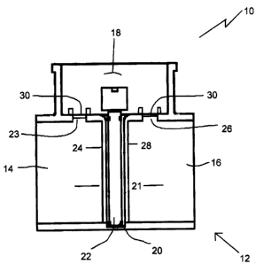
FIG. 1 is a side elevation view, in section, of a first embodiment of plumbing
system
test valve constructed in accordance with the teachings of the present
invention.
FIG. 2 is a side elevation view, in section, of a second embodiment of
plumbing

CA 02505798 2005-04-27
2
system test valve constructed in accordance with the teachings of the present
invention.
DETAILED DESCRIPTION OF THE PREFERRED EMBODIMENT
A first embodiment of plumbing system test valve, generally identified by
reference
numeral 10, will now be described with reference to FIG. 1. A second
embodiment of
plumbing system test valve, generally identified by reference numeral 100,
will now be
described with reference to FIG. 2.
Structure and Relationship of Parts of plumbing system test valve 10:
Referring to FIG. 1, plumbing system test valve 10 includes a valve body 12
defining a first pipe connection 14, a second pipe connection 16, an access
opening 18, a flow
channel 21 that extends between first pipe connection 14 and second pipe
connection 16 and a
valve seat 20. A removable valve member 22 is provided which is adapted to
engage valve
seat 20 of valve body 12 to prevent liquid from flowing along flow channel 21
between first
pipe connection 14 and second pipe connection 16. Removable valve member 22 is
removable through access opening 18. A first fill port 23 is provided which is
adapted to
facilitate filling valve body 12 with liquid on one side of valve member 22.
First fill port 23 is
positioned on first side 24 of valve member 22. A
second fill port 26 is provided which
is adapted to facilitate filling valve body 12 with liquid another side of
valve member 22.
Second fill port 26 is positioned on a second side 28 of valve member 22. In
this first
embodiment, first fill port 23 and second fill port 26 are both sheltered
within access opening
18. It will be understood that in some installations access opening 18 will be
closed by a
removable closure (not shown). It will be understood that in other
installations, body 12 will
be buried and access opening 18 will be accessible through a riser pipe
extending to surface,
with valve member 22 being inserted and removed at the end of a pole. It is
envisaged that
first fill port 23 and second fill port 26 will have removable plugs 30.
Operation of plumbing system test valve 10:
It will be understood that body 12 is incorporated into a plumbing
installation. In
order to test the plumbing system, valve member 22, is inserted through access
opening 18
and engaged with valve seat 20. The positioning of valve member 22 prevents
liquids from

CA 02505798 2005-04-27
3
flowing through body 12 along flow channel 21. That portion of the plumbing
system
upstream of valve member 22 is, therefore, isolated from that portion of the
plumbing system
downstream of valve member 22. By selecting the appropriate fill port, first
fill port 23 or
second fill port 26, either the upstream portion of the plumbing system or the
downstream
portion of the plumbing system can be tested by connecting a water source and
filling the
system with liquid.
Structure and Relationship of Parts of plumbing system test valve 100:
Referring to FIG. 2, plumbing system test valve 100 is similar in most
respects to
plumbing system test valve 10. Identical reference numerals will, therefore,
be used to
identify identical components. However, plumbing system test valve 100 has a
fundamental
difference, that being the positioning of the fill ports. The purpose of
illustrating this
embodiment is to make clear that the fill ports do not have to be sheltered
within the access
opening. Plumbing system test valve 100 includes a valve body 12 defining a
first pipe
connection 14, a second pipe connection 16, an access opening 18, a flow
channel 21 that
extends between first pipe connection 14 and second pipe connection 16 and a
valve seat 20.
A removable valve member 22 is provided which is adapted to engage valve seat
20 of valve
body 12 to prevent liquid from flowing along flow channel 21 between first
pipe connection
14 and second pipe connection 16. Removable valve member 22 is removable
through access
opening 18. A first fill port 123 is provided which is adapted to facilitate
filling valve body
12 with liquid on one side of valve member 22. First fill port 123 is
positioned on first side
24 of valve member 22. A second fill port 126 is provided which is adapted to
facilitate filling
valve body 12 with liquid another side of valve member 22. Second fill port
126 is positioned
on a second side 28 of valve member 22. In this second embodiment, first fill
port 123 and
second fill port 126 are both positioned on valve body 12 on opposed sides of
access opening
18. It will be understood that in some installations access opening 18 will be
closed by a
removable closure (not shown). It will be understood that in other
installations, body 12 will
be buried and access opening 18 will be accessible through a riser pipe
extending to surface,
with valve member 22 being inserted and removed at the end of a pole. It is
envisaged that
first fill port 123 and second fill port 126 will have removable plugs 30.
Operation of plumbing system test valve 100:

CA 02505798 2012-07-30
4
It will be understood that body 12 is incorporated into a plumbing
installation. In
order to test the plumbing system, valve member 22, is inserted through access
opening 18
and engaged with valve seat 20. The positioning of valve member 22 prevents
liquids from
flowing through body 12 along flow channel 21. That portion of the plumbing
system
upstream of valve member 22 is, therefore, isolated from that portion of the
plumbing system
downstream of valve member 22. By selecting the appropriate fill port, first
fill port 123 or
second fill port 126, either the upstream portion of the plumbing system or
the downstream
portion of the plumbing system can be tested by connecting a water source and
filling the
system with liquid.
In this patent document, the word "comprising" is used in its non-limiting
sense to
mean that items following the word are included, but items not specifically
mentioned are not
excluded. A reference to an element by the indefinite article "a" does not
exclude the
possibility that more than one of the element is present, unless the context
clearly requires that
there be one and only one of the elements.
The following claims are to be understood to include what is specifically
illustrated
and described above, what is conceptually equivalent, and what can be
obviously substituted.
The scope of the claims should not be limited by the preferred embodiments set
forth in the
examples, but should be given the broadest interpretation consistent with the
description as a
whole.

Representative Drawing
A single figure which represents the drawing illustrating the invention.
Administrative Status

For a clearer understanding of the status of the application/patent presented on this page, the site Disclaimer , as well as the definitions for Patent , Administrative Status , Maintenance Fee  and Payment History  should be consulted.

Administrative Status

Title Date
Forecasted Issue Date 2013-07-09
(22) Filed 2005-04-27
(41) Open to Public Inspection 2006-10-27
Examination Requested 2010-02-02
(45) Issued 2013-07-09

Abandonment History

There is no abandonment history.

Payment History

Fee Type Anniversary Year Due Date Amount Paid Paid Date
Application Fee $200.00 2005-04-27
Maintenance Fee - Application - New Act 2 2007-04-27 $50.00 2007-01-26
Maintenance Fee - Application - New Act 3 2008-04-28 $50.00 2008-02-13
Maintenance Fee - Application - New Act 4 2009-04-27 $50.00 2009-03-27
Request for Examination $400.00 2010-02-02
Maintenance Fee - Application - New Act 5 2010-04-27 $100.00 2010-02-02
Maintenance Fee - Application - New Act 6 2011-04-27 $100.00 2011-04-01
Maintenance Fee - Application - New Act 7 2012-04-27 $100.00 2012-03-26
Maintenance Fee - Application - New Act 8 2013-04-29 $100.00 2013-03-27
Final Fee $150.00 2013-04-30
Maintenance Fee - Patent - New Act 9 2014-04-28 $100.00 2014-03-28
Maintenance Fee - Patent - New Act 10 2015-04-27 $125.00 2015-03-27
Maintenance Fee - Patent - New Act 11 2016-04-27 $125.00 2016-03-29
Maintenance Fee - Patent - New Act 12 2017-04-27 $125.00 2017-03-31
Maintenance Fee - Patent - New Act 13 2018-04-27 $125.00 2018-04-11
Maintenance Fee - Patent - New Act 14 2019-04-29 $125.00 2019-03-29
Maintenance Fee - Patent - New Act 15 2020-04-27 $225.00 2020-04-17
Maintenance Fee - Patent - New Act 16 2021-04-27 $229.50 2021-04-27
Maintenance Fee - Patent - New Act 17 2022-04-27 $229.04 2022-04-27
Maintenance Fee - Patent - New Act 18 2023-04-27 $236.83 2023-03-16
Maintenance Fee - Patent - New Act 19 2024-04-29 $253.00 2024-03-25
Owners on Record

Note: Records showing the ownership history in alphabetical order.

Current Owners on Record
COSCARELLA, GABE
Past Owners on Record
None
Past Owners that do not appear in the "Owners on Record" listing will appear in other documentation within the application.
Documents

To view selected files, please enter reCAPTCHA code :


To view images, click a link in the Document Description column. To download the documents, select one or more checkboxes in the first column and then click the "Download Selected in PDF format (Zip Archive)" or the "Download Selected as Single PDF" button.

List of published and non-published patent-specific documents on the CPD .

If you have any difficulty accessing content, you can call the Client Service Centre at 1-866-997-1936 or send them an e-mail at CIPO Client Service Centre.


Document
Description 
Date
(yyyy-mm-dd) 
Number of pages   Size of Image (KB) 
Maintenance Fee Payment 2020-04-17 1 33
Representative Drawing 2006-09-29 1 6
Maintenance Fee Payment 2021-04-27 1 33
Maintenance Fee Payment 2022-04-27 1 33
Abstract 2005-04-27 1 19
Description 2005-04-27 4 203
Claims 2005-04-27 2 74
Drawings 2005-04-27 2 23
Cover Page 2006-10-16 2 36
Description 2012-07-30 4 202
Claims 2012-07-30 1 39
Cover Page 2013-06-13 2 36
Correspondence 2005-06-02 1 74
Assignment 2005-04-27 2 84
Correspondence 2006-12-28 1 40
Fees 2007-01-26 1 25
Maintenance Fee Payment 2018-04-11 1 33
Fees 2008-02-13 2 66
Correspondence 2008-02-13 2 66
Fees 2009-03-27 1 31
Correspondence 2009-12-30 1 25
Fees 2010-02-02 1 29
Prosecution-Amendment 2010-02-02 1 29
Correspondence 2010-02-08 1 84
Correspondence 2011-04-27 1 12
Correspondence 2011-04-21 1 12
Correspondence 2011-03-31 3 165
Fees 2011-04-01 1 26
Correspondence 2011-04-14 1 19
Correspondence 2011-04-27 1 19
Fees 2011-04-01 1 27
Prosecution-Amendment 2012-01-31 3 118
Prosecution-Amendment 2012-07-30 6 158
Correspondence 2013-04-30 1 34
Maintenance Fee Payment 2024-03-25 1 33