Note: Descriptions are shown in the official language in which they were submitted.
CA 02506008 2012-03-19
CA 02506008 2005-04-29
21488.04158
REPOSITIONABLE ATTENUATOR
BACKGROUND
[00021 The present invention is directed to an attenuator that can be used in
a variable
air volume terminal unit, a terminal unit incorporating the attenuator, and
clips for fastening the
attenuator.
[00031 Discharge and radiated sound is of concern with variable air volume
(VAV)
terminal units, such as may be used in heating, ventilation, and air
conditioning (HVAC)
systems. In a VAV system, one or more central air supply systems are sized to
meet the peak
cooling (and/or heating) conditions for the building. Several terminal units
are located in
respective zones or offices throughout the building, each connected via ducts
to the central air
supply. In such a terminal unit, the volume of air urged through a diffuser
over a given length of
time is controlled. Some terminal units have a fan or pump driven by a motor
to move the air
from the central air supply through the diffuser associated with the terminal
unit. VAV terminal
units permit "personalizing" the temperature of a particular room or group of
rooms as desired
by the occupants.
[00041 While there may be several sources of objectionable sound in a HVAC
system, at least every component of rotating machinery, e.g., the blower of an
air handling unit,
generates sound waves which propagate along the duct through the air flowing
in the duct. And
certain types of VAV terminal units include integral motor-driven fans. Unless
attenuated to
acceptable levels, the propagated sound waves may be evident to persons in the
rooms served by
the HVAC system. Conventional attenuators for this sound are external to the
terminal unit and
are either supplied and installed by the factory or are installed to the
terminal unit in the field.
(WMH0736.DOC;1 )
1
CA 02506008 2005-04-29
21488.04158
SUMMARY
[00051 An attenuator described in the present disclosure has at least one open
side
and is internal to the terminal unit and is positionable between at least two
positions relative to
the casing of the unit. Also described is a terminal unit having an attenuator
that is positionable
between at least a first position and second position. A kit is also described
for fitting a terminal
unit with a repositionable attenuator. Also described are clips suitable for
use with the
repositionable attenuator to allow for repositioning of the attenuator.
BRIEF DESCRIPTION OF THE DRAWINGS
[0006] In the accompanying drawings, which are incorporated in and constitute
a part
of this specification, embodiments of the invention are illustrated, which,
together with a general
description of the invention given above, and the detailed description given
below, serve to
exemplify the principles of this invention, wherein:
[00071 Figure 1 is a perspective view illustrating a terminal unit in
accordance with
the present invention illustrating the attenuator in an "out" position;
[00081 Figure 2 is a perspective view illustrating the terminal unit of Figure
1 with
the attenuator in an "in" position;
[0009] Figure 3 is a top view of the terminal unit of Figure 1;
[00101 Figure 4 is a perspective view of the terminal unit of claim 1;
[00111 Figure 5 is a perspective view of an attenuator in accordance with the
present
invention;
[00121 Figure 6 is a top view of an attenuator clip in accordance with the
present
invention; and
[00131 Figures 7A through 7F are schematic drawings of an attenuator clip in
accordance with the present invention.
(WMH0736.DOC;I) 2
CA 02506008 2005-04-29
21488.04158
DETAILED DESCRIPTION
[00141 The present invention is described by exemplary embodiments herein, but
is
limited only by the claims appended hereto. The invention is capable of many
embodiments,
depending on the specific circumstances of each desired implementation.
Departures from the
embodiments described herein may be made by those of ordinary skill in the art
without undue
experimentation to accommodate a variety of specific implementations without
departing from
the spirit and scope of the invention.
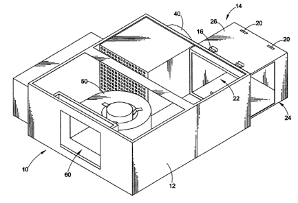
[00151 Figure 1 illustrates a VAV terminal unit 10 having a casing 12, an
attenuator
14, and attenuator clips 16. Figures 1 through 4 illustrate the terminal unit
10 without a top
portion of the casing 12 to enable illustration of the internal components of
the terminal unit 10.
[00161 The attenuator 14 is capable of being positioned, such as by sliding,
relative to
the casing 12 between a first, or "out," position illustrated in Figure 1 and
a second, or "in,"
position illustrated in Figure 2. In the "out" position, more of the
attenuator 14 is outside of the
casing 12 of the terminal unit 10 than inside the casing 12. In the "in"
position, more of the
attenuator 14 is inside the casing 12 of the terminal unit 10 than outside of
the casing 12. The
attenuator 14 may also be completely removed from the casing 12, for example,
to replace the
attenuator 14.
[00171 Attenuator clips 16 cooperate with appropriate slots 18, 20 on the top
of the
attenuator 14 to retain the attenuator 14 in the "out" or "in" position. The
attenuator 14 may also
be secured in any position intermediate to the "in" or the "out" positions.
Slots 18, 20 may be
situated at any location on the attenuator 14 to facilitate securing the
attenuator 14 in any
position between fully removed from the casing 12 and completely inserted
within the casing 12.
[00181 In one embodiment, the attenuator clips 16 are attached to the casing
12, such
as via holes 30 illustrated in Figures 6 and 7A-7C. Fasteners 32 cooperate
with the holes 30 and
the casing 12 to retain the attenuator clips on the casing 12. The fasteners
32 may be any
conventional fasteners, such as rivets, brads, screws, bolts, studs, pins,
etc., without departing
from the spirit and scope of the invention.
(WMHO736_DOC;I ) 3
CA 02506008 2005-04-29
21488.04158
[00191 In one embodiment, the attenuator clips 16 are removably fastened to
the
casing 12, such as by removable fasteners 32. In another embodiment, the
attenuator clips 16 are
secured to the casing 12 without fasteners 32, such as with an adhesive, glue,
resin, or the like.
In another embodiment, fasteners 32 are integral with the casing 12, such as
integral protrusions
over which the holes 30 snap into place.
[00201 Attenuator clips 16 may also be provided to cooperate with slots 18, 20
located on the bottom or the sides of attenuator 14, as illustrated in Figure
1.
[00211 Figures 3 and 4 illustrate the attenuator 14 in the "out" position,
with the
attenuator clips 16 positioned to cooperate with slots 18.
[00221 Figure 5 illustrates the attenuator 14 having four slots 18, 20 in a
top surface
27 thereof, with corresponding slots 18, 20 in a bottom surface 28. Any number
of slots 18, 20
may be provided in the attenuator 14 without departing from the spirit and
scope of the
invention. The attenuator 14 may also be secured in the "in" position and the
"out" position in
any other manner presently known or later developed.
[00231 The attenuator 14 illustrated in Figures 1 and 5 has a body 26 with
generally a
rectangular prismatic shape with a first side 22 and a second side 24 open or
at least not
completely closed off. The shape of the body 26 of the attenuator 14 can also
be described as a
hollow box-like structure having the first side 22 and the second side 24
open, or at least not
completely closed off. The first side 22 is disposed within the casing 12. The
location of the
second side 24 relative to the terminal unit 10 and the first side 22 is
dependent on the geometry
of the components of the particular terminal unit 10 and may be selected
without departing from
the spirit or scope of the invention.
[0024] The relative location of the attenuator 14 within the terminal unit 10
is
generally dependent on the geometry and locations of the components within the
terminal unit
10, and may be selected without departing from the spirit and scope of the
invention.
[00251 When the attenuator 14 is in the "out" position, a flow path is enabled
from
outside the terminal unit 10, through the second side 24, into the attenuator
14, through the first
side 22, and into the interior of the terminal unit 10. For example, if the
terminal unit is placed
{ WMH0736.DOC;1) 4
CA 02506008 2005-04-29
21488.04158
in an HVAC system, the ambient air outside of the terminal unit 10 may be
forced into the
terminal unit 10 through the described flow path. The ambient air then mixes
with chilled air
provided to the interior of the terminal unit 10, such as through a primary
air inlet 40 that is in
communication with a chiller system. Then a fan 50 forces the mixed ambient
and chilled air
through an outlet 60 into a room, conduit, etc. in communication with the
outlet 60.
[0026] Use of an attenuator 14 that is internal to and part of the terminal
unit 10 may
enable more accurate predictions for sound mitigation values because the
attenuator 14 is a part
of the terminal unit 10 and not an after-market addition that may or may not
have been tested
with the particular terminal unit 10. The attenuator 14 and the terminal unit
10 may occupy less
space than a conventional unit because the attenuator 14 is internal to the
terminal unit 10,
possibly resulting in reduced costs for shipping, storage, etc. Also, there
may be lower labor
costs associated with installation of the attenuator and terminal unit of the
present invention.
[0027] Conventional field-added attenuators can introduce undesirable
performance
characteristics into operation of a terminal unit, such as fan shift. This can
result because the
particular after-market, external attenuator may not have been tested with the
specific terminal
unit, and the operation of the existing terminal unit may have been optimized
without the
presence of an external attenuator. The terminal unit with repositionable
attenuator of the
present invention is unlikely to experience fan shift or other such
undesirable performance
characteristics, because any optimization of the terminal unit operation will
be conducted with
the attenuator as a part of the original manufacture of the terminal unit.
[0028] Figures 6 and 7A-7F illustrate an attenuator clip 16. As discussed
above, in
one embodiment, the attenuator clip 16 is provided with two holes 30 in a flat
section 74. The
holes 30 enable the attenuator clip 16 to be fastened to the casing 12. There
may be any number
of holes 30 in the attenuator clip 16. In other embodiments, the attenuator
clip 16 does not have
holes, and is fastened to the casing in other manners, as discussed above.
[0029] As best seen in Figures 7C and 7D, in one embodiment the attenuator
clip 16
has a V-shaped section, indicated generally by numeral 70. The bottom 72 of
the V-shaped
section 70 cooperates with the slots 18, 20 to hold the attenuator 14 in place
in the "in" or the
"out" position. The V-shaped section 70 is connected to the flat section 74.
In the embodiment
(WMH0736.DOC;I 1 5
CA 02506008 2005-04-29
21488.04158
illustrated in Figures 7A-7D, the V-shaped section 70 is connected to the flat
section 74 via a
curved section 76, although direct connection to the flat section 74 is within
the spirit and scope
of the invention. The curved section 76 is believed to assist with the
resiliency of the clip 16 and
in the capability of the clip 16 to be biased toward and disengaged from the
slot 18, 20. The clip
16 also includes a tab 78 extending from a portion of the V-shaped section 70
closest to the flat
section 74 toward the flat section 74, as illustrated in Figure 7D.
[00301 The attachment of the clip 16 to the casing 12 is such that the V-
shaped
section 70 is disposed to be capable of cooperation with slot 18, 20. When the
slot 18, 20 and
the V-shaped section 70 are aligned to cooperate, at least a portion of the V-
shaped section 70
enters the slot 18, 20 to a sufficient depth to secure the attenuator 14. The
tab 78 prevents
insertion of the V-shaped section 70 to an undesired depth in the slot 18, 20
and enables
sufficient structure of the clip 16 to be available to disengage the clip 16
to reposition the
attenuator 14.
[00311 The bottom 72 of the V-shaped section 70 is offset from the plane of
the flat
section 74, for example, "below" the plane of the flat section 74, as
illustrated in Figure 7D.
This assists in providing a bias of the bottom 72 against the body of the
attenuator 14 and the slot
18, 20. Thus, when the slot 18, 20 aligns with the bottom 72, the bottom 72
and V-shaped
section 70 will "snap" into place in the slot 18, 20. Force must then be
applied to the clip 16 to
"lift" or disengage the bottom 72 and the V-shaped section 70 from the slot
18, 20. The clip 16
preferably has sufficient resiliency to enable the disengagement of the V-
shaped section 70 from
the slot 18, 20 without detachment of the clip 16 from the casing 12.
[00321 For clips 16 and slots 18, 20 associated with the bottom surface 28 of
the
attenuator, the operation and cooperation are the same, but the directions are
different. For
example, the bottom 72 is disposed "above" the plane of the flat section 74.
[00331 When it is desired to reposition the attenuator 14, the V-shaped
section 70 is
disengaged from the slot 18, 20, allowing movement of the attenuator 14 to a
different position.
When the same or different slot 18, 20 is then aligned with the same or
different V-shaped
section 70, the V-shaped section 70 engages the slot 18, 20 to secure the
attenuator 14 at the
different position.
(WM H0736.DOC; I) 6
CA 02506008 2005-04-29
21488.04158
[0034] If there is more than one clip 16 and slot 18, 20, then all clips 16
must be
disengaged before the attenuator 14 is moved to the different position. As
illustrated in the
Figures, for example, there are a plurality of clips 16 and slots 18, 20 to
provide for a plurality of
positions of the attenuator 14.
[00351 The clips also provide some support to the attenuator 14, particularly
when it
is in its "out" position. The cooperation between the slot 18, 20 and the clip
14 also provide
some protection against unintentionally completely disengaging the attenuator
14 from the
casing 12.
[0036] In one embodiment, the attenuator clip 16 is made from high carbon
spring
steel. The attenuator clip 16 may be made from any material without departing
from the spirit
and scope of the invention.
[0037] The attenuator 14 and attenuator clips 16 of the present invention may
also be
used to retrofit existing terminal units, such as in a kit, depending on the
geometry, component
location, and other parameters of a particular existing terminal unit.
[0038] In one example of operation, the attenuator 14 is placed in the "in"
position
for shipping, storage, etc. When the terminal unit 10 is installed, or for
testing, etc., the
attenuator clips 16 engaging the slots 20 are disengaged and the attenuator 14
is repositioned to
the "out" position. The attenuator clips 16 are then placed in engagement with
the slots 18 to
secure the attenuator 14 in the "out" position. If desired, the attenuator 14
may be completely
removed from the casing 12 and the attenuator clips 16 not engaged with the
slots 18, 20.
[0039] The attenuator 14 may be replaced in the "in" position by disengaging
the
attenuator clips 16 from the slots 18, repositioning the attenuator 14 to the
"in" position, and
engaging the attenuator clips 16 with slots 20.
[0040] While the present invention has been illustrated by the above
description of
embodiments, and while the embodiments have been described in some detail, it
is not the
intention of the Applicants to restrict or in any way limit the scope of the
invention to such
detail. Additional advantages and modifications will readily appear to those
skilled in the art.
For example, the attenuator 14 could be arranged to cooperate with the top or
bottom of the
(WMH0736,DOC;I ) 7
CA 02506008 2005-04-29
21488.04158
casing 12 such that the attenuator 14 is repositionable vertically. Or the
attenuator 14 could be
arranged to cooperate with a side of the casing 12, instead of the rear of the
casing 12, as
illustrated and described. Therefore, the invention in its broader aspects is
not limited to the
specific details, representative apparatus and methods, and illustrative
examples shown and
described. Accordingly, departures may be made from such details without
departing from the
spirit or scope of the Applicants' general or inventive concept.
{ WMH0736.DOC;1 } 8