Note: Descriptions are shown in the official language in which they were submitted.
CA 02506067 2005-05-13
WO 2004/046422 PCT/GB2003/004968
COMPOSITE SACRIFICIAL ANODES
The invention relates to composite sacrificial anodes,
particularly but not exclusively, based on magnesium, and
to methods for their production.
Magnesium or magnesium. alloy sacrificial anodes have been
used for many years to ~ provide cathodic corrosion
protection for iron and steel engineering products,
particularly in the oil industry. This technique is used
to protect pipelines, marine oil installations, ships and
other large steel constructions which are exposed to a
corrosive environment such as the sea or wet ground.
The anode is immersed in the corrosive environment and is
electrically connected to the structure to be protected
either by physical attachment or through an electrical
connection such as a cable or conductive bolt or strap.
The corrosion protection provided by the anode can be
measured in two ways: the potential (voltage) of the
anode, and the output capacity of the anode measured as
amp-hours per kilogram of the sacrificial magnesium
alloy.
There are at present three commonly used magnesium alloys
that meet ASTM B843-93, namely (a) magnesium with
0.5-1.3% by weight manganese which produces a voltage of
1.7V,(b) magnesium with 5.3-6.7o by weight aluminium,
2.5-3.5% by weight zinc and 0.15-0.7o by weight
manganese, and (c) magnesium with 2.5-3.5% by weight
aluminium, 0.6-1.4% by weight zinc and 0.2-1.0o by weight
manganese, both (b) and (c) producing a voltage of 1.5V.
CA 02506067 2005-05-13
WO 2004/046422 PCT/GB2003/004968
The output capacity is affected by both the alloy used
and by the method of manufacture of the anode. In
particular, the cooling rate of the metal during
solidification has been found to be important. (Juarez-
Islas et. al 1993). The theoretical value for the output
capacity for magnesium alloys is 2400 Ahr/kg. However it
is reported that typical anodes are only 30-35%
efficient.
The present invention will be described with reference to
the accompanying drawings, in which:
Figure 1 shows a side view and an end view of a
conventional anode,
Figure 2 is perspective view of a composite anode of the
present invention, and
Figure 3 is a schematic side view of a casting apparatus
suitable for forming a segment of the anode of Figure 2.
Currently, cast magnesium anodes are 'D' shaped and are
of the type shown in accompanying Fig 1. The anode (1)
is manufactured by casting a sacrificial magnesium alloy
(2) around a centrally placed steel insert (3) laid
horizontally in an open top permanent mould, usually
manufactured of cast iron. The insert (3) provides both
the mechanical and the electrical connection between the
anode (1) thus formed and the structure to be protected
(not shown). A bitumen mastic (4) is coated over the end
of the anode (1), where the insert (3) protrudes from the
alloy (2) in order to avoid premature corrosion of the
sacrificial alloy (2) in the region of its junction with
CA 02506067 2005-05-13
WO 2004/046422 PCT/GB2003/004968
the insert (3). The 'D' shape cross-section facilitates
removal of the casting from the mould. This conventional
method of manufacture typically results in a variable
metal cooling rate both within individual anodes, and
between anodes within a batch. In the case of large
anodes, i.e. greater than 10 kg, or very large anodes
i.e. greater than 100 kg, for example in the region of 5
tonnes, the solidification rate in the centre of the
anode will be substantially lower than that at the edge.
This results in the electrochemical efficiency of
conventional anodes being both poor and variable.
This invention relates to sacrificial anodes,
particularly of magnesium or a magnesium alloy, which
have improved performance with respect to output
capacity, especially for large and very large anodes.
This is achieved by effectively dividing up alarge anode
into smaller parts, each of which is preferably produced
under carefully controlled conditions. Each part of such
composite anode is arranged to function on its own, but
together the parts behave as a single anode. The parts
must be joined together in such a way that their
corrosion takes place essentially only on their outermost
exposed surfaces. In particular it should be ensured
that there is no premature corrosion of the sacrificial
material in the region of its electrical connection with
the structure to be protected before the material remote
from that connection has been corroded, particularly when
the electrical connection is offset in the material, i.e.
not centrally placed.
US-A-5,294,396 describes a segmented anode for direct
attachment to a pipeline to be protected.
CA 02506067 2005-05-13
WO 2004/046422 PCT/GB2003/004968
By contrast the anodes of the present invention are
connected electrically to the structure to be protected
only indirectly through their electrical connection
without the sacrificial material of the anodes being in
direct electrical contact with the structure.
In accordance with the present invention there is
provided a composite sacrificial anode for immersion in a
corrosive environment comprising a plurality of castings
of a sacrificial material each disposed around a
corresponding electrical connector for attachment to a
structure to be protected, a part of the surface of each
segment being protected from corrosion by the environment
by being adjacent at least one other segment, wherein the
castings are connected together electrically only via
their electrical connectors.
By being connected via their electrical connector to the
structure to be protected, each casting behaves as a part
or segment of a large composite anode. Physical but non-
electrical connection between the composite anode and the
structure to be protected can be provided by means of
cables, straps, adhesives or the like as required. a
Preferably each electrical connector extends into its
corresponding casting in the casting direction, and the
sacrificial material of each casting is protected from
external corrosion in the region of its attachment to its
connector.
The present invention also provides a method of producing
a composite sacrificial anode for immersion in a
corrosive environment and having an electrical connection
CA 02506067 2005-05-13
WO 2004/046422 PCT/GB2003/004968
for attachment to the structure to be protected, which
method comprises casting a plurality of segments of a
sacrificial material each in contact with a corresponding
electrical connector, each connector being at least
partly within its corresponding individual segment, and
electrically connecting the segments together only via
their electrical connectors.
The segments of the composite anode can be grouped
together in a variety of different arrangements, such as
in a chain or circle, but in order to maximise the life
of the composite anode the segments are preferably
arranged in the form of a block in which each segment is
adjacent at least two other segments. Electrical
insulation between adjacent segments can be provided by
spacing them apart or by the interposition of an
insulating layer, such as a surface coating of insulating
resin or mastic. The external shape of the composite
anode can be cubic, rectangular, cylindrical or any other
regular or irregular solid shape, depending upon the
particular corrosion environment into which the anode is
intended to be immersed, especially if it is required to
fit into or around the structure which it is intended to
protect. The shape of each segment can be varied in
accordance with the solid shape of the composite anode
and the shape of adjacent segments. Suitable segment
shapes are cubes, rectangles, sectors and cones.
Each electrical connector is preferably substantially
straight and fully aligned with the casting direction of
its segment, although some deviation is possible. Each
connector is generally smooth, although some roughening,
ridges, grooves and the like may be helpful for
facilitating good electrical and physical connection with
CA 02506067 2005-05-13
WO 2004/046422 PCT/GB2003/004968
the sacrificial material. An individual connector may
also take the form of a plurality of separate connectors
embedded in the same casting.
In a preferred embodiment of the present invention a
waterproof mastic or resin is used to coat the surfaces
of the segments around their exposed connectors, where
the connectors are on or near the surface of the
segments. Preferably each segment is identical and is
assembled together with the other segments to form a
composite anode in the form of a block, with any gaps
between the segments being filled with an electrically
insulating waterproof mastic or resin to prevent
corrosion of the interior of the composite anode.
Conveniently in such an arrangement the individual
connectors are cast in an off-centre position in each
segment; so that when assembled together their connectors
are close together and thus easier to join.
It is preferred that there are no voids within the
composite anode, i.e. the segments extend substantially
to the centre of the anode, with any internal spaces
between the segments being filled with. the mastic or
resin.
By providing each of the segments with its own electrical
connector and by arranging for those individual
electrical connectors to be joined, an electrical pathway
between each anode segment and the structure to be
protected is ensured throughout the corrosion life of
each segment.
CA 02506067 2005-05-13
WO 2004/046422 PCT/GB2003/004968
Additional physical connections can be provided between
the different segments, such as by strapping them
together with one or more bands, but any such additional
connections must be non-electrical and must not allow the
formation of voids between the segments into which the
corrosive environment could ingress during the corrosion
of the composite anode. The waterproof mastic or resin
should therefore fill any gaps, preferably totally,
between these segments so that even when segments are
well corroded their further corrosion continues to take
place essentially only on their outermost surfaces and
not between them. Generally an electrically insulating
mastic or resin is used, such as pitch or a polyurethane
resin.
In the most preferred embodiment of the present invention
each segment, of preferably a magnesium or magnesium
alloy, is cast using direct chill (DC) casting
technology. This is a method of manufacture currently
used to produce magnesium slabs or billets as described
in, for example, Grandfield, J. and McGlade, P. ~~DC
Casting of Aluminium: Process Behaviour Magnesium
Technology", Materials Forum Australia, Volume 20, 1996,
p. 29-51. The preferred casting method is a modification
of this known production method which allows for the
introduction of a conductive insert into the cast
magnesium or magnesium alloy billet or slab so as to
produce an anode. This is shown schematically in Fig. 3,
and, as will be described in more detail hereinafter,
each insert is preferably positioned off-centre near one
of the walls of the mould and aligned with the casting
direction.
CA 02506067 2005-05-13
WO 2004/046422 PCT/GB2003/004968
Each off-centre insert, which is preferably a galvanised
straight smooth mild steel bar, protrudes from its
respective casting so that when the segments of the
composite anode are assembled together their respective
inserts can be joined together to provide both a
mechanical and an electrical connection to the structure
to be protected. Generally the protruding ends of the
inserts are welded together and joined to a main
connector, such as a cable clamp, which is integral with
or else attached to the inserts, for example by welding,
so as to provide the electrical connection to the
structure to be protected.
One embodiment of the present invention will now be
described by way of example with reference of
accompanying Figures 2 and 3.
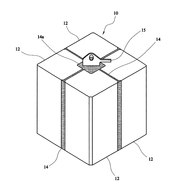
The composite anode (10) is in the form of a rectangular
block of a square cross-section and is composed of four
rectangular segments (12) of square cross-section fitted
together in the form of a block. Each segment (12) has
been formed by continuously casting a sacrificial
magnesium alloy as will be described later. In order to
prevent corrosion of the interior of the anode (10), the
adjacent surfaces of the segments (12) are coated with an
insulating mastic or resin (14) before being assembled
together to form the block. The four segments (12) are
arranged close together but are not directly touching
along their lengths inside the anode (10). Each segment
(12) is provided with an insert in the form of a steel
bar (17 in Figure 3) which extends through the whole
length of its respective segment and to just beyond both
end surfaces of its respective segment (12). The bars
are off-set and all four bars are joined together where
CA 02506067 2005-05-13
WO 2004/046422 PCT/GB2003/004968
they are exposed or protrude from their segments by
welding.
To one of the welded junctions a cable connector (15) is
welded, and at both ends of the joined segments the
welded junctions are covered by additional mastic (14a)
with only the cable connector (15) exposed. An electrical
wire or cable (not shown) is then attached to the exposed
cable conductor (15) for connecting the composite anode
(10) to the structure to be protected (not shown).
Referring to Figure 3, the apparatus for continuously
casting the segments (12) of Figure 2 comprises a
conventional movable casting platform (31) with its mould
(32) and water spray rings (33) arranged in a
conventional manner for DC casting.
The molten sacrificial magnesium alloy (16) is fed to the
mould by reservoir (34). The molten metal is cooled
under controlled conditions by the water emitted from
spray rings (33) whilst the casting platform (31) is
lowered to form the cast segment (12).
In order to provide the electrical connection for each
cast segment (12) a ridged steel insert (17) is held
vertically within the mould (32) so that the alloy (16)
is cast around the bar (17). The bar (17) is located
off-centre but aligned with the casting direction so as
to facilitate its joining with the other bars of the
other segments (12) as shown in Figure 2.
In order to be able to join together the respective ends
of the four bars (17) of the four segments (12) the bar
(17) which is shown being cast in Figure 3 protrudes
CA 02506067 2005-05-13
WO 2004/046422 PCT/GB2003/004968
slightly out of the base of the movable mould (35) and is
also left protruding out of the top of the segment (12)
after casting has been completed.
The use of this DC casting method for the segments (12)
enables a uniform, controllable and rapid cooling process
to be applied to each segment by the controlled direct
cooling of the casting with a water spray. This results
in an improved electrochemical efficiency for the
composite anode over a permanent mould cast anode of the
same size.
Table 1 sets out the typical output capacity from a
conventionally cast anodes compared to that from anodes
produced by DC casting.
Anode type Energy capability(Ahr/Kg)
Conventionally Cast 700 - 1000
DC cast 1200 - '1700
Table 1. Typical energy capability of conventionally vs.
DC cast anodes.
The present invention is particularly suitable for
fabricating very large anodes, e.g. in the region of 5
tonnes. By combining two or more anode sections together
the composite behaves as one large anode. The sections
used in the composite may be produced by DC casting or by
conventional permanent mould casting. In either case,
the fabricated anode produces an improved electrochemical
efficiency over a single permanent mould cast anode of
the same size since the cooling and solidification rates
of the individual segments are faster and more controlled
than would be the case if the anode were cast in one
piece.
CA 02506067 2005-05-13
WO 2004/046422 PCT/GB2003/004968
By linking the inserts of each segment together and
sealing the spaces between them using preferably pitch,
the composite anode is caused to corrode from the outside
only, and hence provides an electrical voltage and
current flow equivalent to a single block anode.