Language selection

Search

Patent 2506145 Summary

Third-party information liability

Some of the information on this Web page has been provided by external sources. The Government of Canada is not responsible for the accuracy, reliability or currency of the information supplied by external sources. Users wishing to rely upon this information should consult directly with the source of the information. Content provided by external sources is not subject to official languages, privacy and accessibility requirements.

Claims and Abstract availability

Any discrepancies in the text and image of the Claims and Abstract are due to differing posting times. Text of the Claims and Abstract are posted:

  • At the time the application is open to public inspection;
  • At the time of issue of the patent (grant).
(12) Patent Application: (11) CA 2506145
(54) English Title: PUMP BOTTLE FLOW CONTROL APPARATUS
(54) French Title: DISPOSITIF DE REGLAGE DU DEBIT D'UNE BONBONNE A POMPE
Status: Dead
Bibliographic Data
(51) International Patent Classification (IPC):
  • B65D 47/34 (2006.01)
  • B05B 11/02 (2006.01)
(72) Inventors :
  • ROBERTSON, DAVID (Canada)
(73) Owners :
  • ROBERTSON, DAVID (Canada)
(71) Applicants :
  • ROBERTSON, DAVID (Canada)
(74) Agent: THOMPSON, DOUGLAS B.
(74) Associate agent:
(45) Issued:
(22) Filed Date: 2005-04-28
(41) Open to Public Inspection: 2006-10-28
Availability of licence: N/A
(25) Language of filing: English

Patent Cooperation Treaty (PCT): No

(30) Application Priority Data: None

Abstracts

English Abstract


A pump bottle flow control apparatus consists of a bottle and pump
combination.
The bottle has a bottom and a peripheral side wall that rises from the bottom
terminating at its
upper extremity in a top opening. The bottle has an interior sump, serving as
a lowermost
portion of the bottle into which liquid flows by force of gravity. The pump is
secured to the
top opening of the bottle. The pump has a manual actuator and a rigid supply
tube that
extends into the bottle and terminates within the interior sump.


Claims

Note: Claims are shown in the official language in which they were submitted.


4

What is Claimed is:

1. A pump bottle flow control apparatus, comprising in combination:
a bottle having a bottom and a peripheral side wall that rises from the bottom
terminating at its upper extremity in a top opening, the bottle having an
interior sump serving
as a lowermost portion of the bottle into which liquid flows by force of
gravity;
a pump secured to the top opening of the bottle, the pump having a manual
actuator
and a rigid supply tube that extends into the bottle and terminates within the
interior sump.

2. The apparatus as defined in Claim 1, wherein the sump has defining walls
converging to a
relatively narrow terminus at the bottom of the bottle, and the rigid supply
tube that extends
into the bottle and terminates within the terminus of the interior sump, such
that the
converging walls direct liquid contents within the bottle by force of gravity
to the supply tube.

3. The apparatus as defined in Claim 2, wherein there are two converging walls
which form a
trough to direct liquids to the sump.

4. The apparatus as defined in Claim 2, wherein the converging walls form a
conical funnel to
direct liquids to the sump.

5. The apparatus as defined in Claim 2, wherein there are at least three
converging walls
which form a funnel to direct liquids to the sump.

6. The apparatus as defined in Claim 5, wherein there are four converging
walls which form a
funnel to direct liquids to the sump.


Description

Note: Descriptions are shown in the official language in which they were submitted.


CA 02506145 2005-04-28
1
TITLE OF THE INVENTION:
Pump Bottle Flow Control Apparatus
FIELD OF THE INVENTION
The present invention relates to a pump bottle apparatus that provides better
control of
flow.
BACKGROUND OF THE INVENTION
Pump bottle apparatus are in common use in North American households. They
each
consist of a bottle having a top opening, with a pump secured to the top
opening. The pump
has a manual actuator and a rigid supply tube that extends into the bottle.
Upon movement of
the manual actuator, liquids from the bottle are pumped up the rigid supply
tube.
SUMMARY OF THE INVENTION
According to the present invention there is provided a pump bottle flow
control
apparatus, which consists of a bottle and pump combination. The bottle has a
bottom and a
peripheral side wall that rises from the bottom terminating at its upper
extremity in a top
opening. The bottle has an interior sump, serving as a lowermost portion of
the bottle into
which liquid flows by force of gravity. The pump is secured to the top opening
of the bottle.
2 0 The pump has a manual actuator and a rigid supply tube that extends into
the bottle and
terminates within the interior sump.
BRIEF DESCRIPTION OF THE DRAWINGS
These and other features of the invention will become more apparent from the
2 5 following description in which reference is made to the appended drawings,
the drawings are
for the purpose of illustration only and are not intended to in any way limit
the scope of the
invention to the particular embodiment or embodiments shown, wherein:
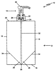
FIG. 1 is a side elevation view, in section, of a pump bottle flow control
apparatus
constructed in accordance with the present invention.
3 0 FIG. 2 is a top plan view, in section, of a first embodiment of pump flow
control
bottle apparatus.
FIG. 3 is a top plan view, in section, of a second embodiment of pump flow
control

CA 02506145 2005-04-28
2
bottle apparatus.
FIG. 4 is a top plan view, in section, of a third embodiment of pump bottle
flow
control apparatus.
DETAILED DESCRIPTION (~F THE PREFERRED EMBODIMENT
The prefer-ed embodiment, a pump bottle flow control apparatus generally
identified
by reference numeral 10, will now be described with reference to FIG.1 through
4.
Structure and Relationship of Parts:
Referring to FIG. 1, pump bottle flow control apparatus 10 is a combination of
a
bottle 12 and a pump 14. Bottle 12 has a bottom 16 and a peripheral side wall
18 that rises
from bottom 16, terminating at its upper extremity 20 in a tubular neck 22
defining a top
opening 24. Bottle 12 has an interior sump, generally identified by reference
numeral 26.
Interior sump 26 is a lowermost portion of bottle 12, which results in liquid
flowing into
interior sump 26 by force of gravity. Pump 14 is secured over top opening 24
of bottle 12, by
engaging exterior threads 28 on tubular neck 22. Pump 14 has a manual actuator
30 and a
rigid supply tube 32. Supply tube 32 extends through top opening 24 into
bottle 12 and
terminates within interior sump 26. Interior sump 26 has walls 34 converging
to a relatively
narrow terminus 36 at bottom 16 of bottle 12. Supply tube 32 terminates within
terminus 36
2 0 of interior sump 26.
Referring to FIG. 2, there is illustrated a first embodiment of pump bottle
apparatus
10 in which there are two converging walls 34. In this embodiment, converging
walls 34
serve to form a trough which directs liquids to interior sump 26.
Refernng to FIG. 3, there is illustrated a second embodiment of pump bottle
apparatus 10 in which converging walls 34 form a conical funnel which directs
liquids to
interior sump 26.
3 0 Referring to FIG. 4, there is illustrated a third embodiment of pump
bottle apparatus
10 in which four converging walls 34 from a four sided funnel which directs
liquids to interior
sump 26.

CA 02506145 2005-04-28
3
Operation:
The use and operation of pump bottle apparatus 10 will now be described with
reference to FIG. 1 through 4. In the prior art, problems were encountered in
maintaining a
steady flow of liquid from the bottle and, in particular, pumping the remnants
of liquid from
bottle 12. Referring to FIG.1, with pump bottle apparatus 10 converging walls
34 of interior
sump 26 serve to direct liquid contents within bottle 12 by force of gravity
to supply tube 32.
As a result, recovery of liquid from bottle 12 is improved. As is apparent
from a review of
FIG. 2, 3, and 4, there are several ways in which converging walls 34 can be
configured to
create interior sump 26.
In this patent document, the word "comprising" is used in its non-limiting
sense to
mean that items following the word are included, but items not specifically
mentioned are not
excluded. A reference to an element by the indefinite article "a" does not
exclude the
possibility that more than one of the element is present, unless the context
clearly requires that
there be one and only one of the elements.
It will be apparent to one skilled in the art that modifications may be made
to the
2 0 illustrated embodiment without departing from the spirit and scope of the
invention as
hereinafter defined in the Claims.
Representative Drawing
A single figure which represents the drawing illustrating the invention.
Administrative Status

For a clearer understanding of the status of the application/patent presented on this page, the site Disclaimer , as well as the definitions for Patent , Administrative Status , Maintenance Fee  and Payment History  should be consulted.

Administrative Status

Title Date
Forecasted Issue Date Unavailable
(22) Filed 2005-04-28
(41) Open to Public Inspection 2006-10-28
Dead Application 2010-04-28

Abandonment History

Abandonment Date Reason Reinstatement Date
2009-04-28 FAILURE TO PAY APPLICATION MAINTENANCE FEE

Payment History

Fee Type Anniversary Year Due Date Amount Paid Paid Date
Application Fee $200.00 2005-04-28
Maintenance Fee - Application - New Act 2 2007-04-30 $50.00 2007-02-08
Maintenance Fee - Application - New Act 3 2008-04-28 $50.00 2008-02-13
Owners on Record

Note: Records showing the ownership history in alphabetical order.

Current Owners on Record
ROBERTSON, DAVID
Past Owners on Record
None
Past Owners that do not appear in the "Owners on Record" listing will appear in other documentation within the application.
Documents

To view selected files, please enter reCAPTCHA code :


To view images, click a link in the Document Description column. To download the documents, select one or more checkboxes in the first column and then click the "Download Selected in PDF format (Zip Archive)" or the "Download Selected as Single PDF" button.

List of published and non-published patent-specific documents on the CPD .

If you have any difficulty accessing content, you can call the Client Service Centre at 1-866-997-1936 or send them an e-mail at CIPO Client Service Centre.


Document
Description 
Date
(yyyy-mm-dd) 
Number of pages   Size of Image (KB) 
Representative Drawing 2006-10-02 1 5
Description 2005-04-28 3 121
Abstract 2005-04-28 1 15
Claims 2005-04-28 1 33
Drawings 2005-04-28 2 23
Cover Page 2006-10-18 1 30
Correspondence 2005-06-07 1 33
Assignment 2005-04-28 3 89
Correspondence 2007-01-02 1 40
Fees 2007-02-08 1 26
Fees 2008-02-13 2 68
Correspondence 2008-02-13 2 69
Correspondence 2009-06-23 1 104
Correspondence 2009-12-30 1 24