Note: Descriptions are shown in the official language in which they were submitted.
CA 02506447 2005-05-17
WO 2004/045430 PCT/US2003/037028
TENACULUM-LIKE DEVICE FOR INTRAVAGINAL INSTRUMENT DELIVERY
FIELD OF THE INVENTION
[0001]The invention generally relates to the field of holding and manipulating
body tissue such as a female patient's uterine cervix in the treatment of
various uterine disorders.
BACKGROUND OF THE INVENTION
[0002] It is often desirable to hold, maneuver, and retain tissue during
medical
procedures. Devices for gripping, holding, and manipulating tissue are thus
often very useful during medical procedures, particularly ones involving
tissues, organs, and structures that are relatively inaccessible or otherwise
difficult to reach or to retain.
[0003] In many medical procedures, it is useful to locate the cervix and
cervical os of a female patient. For example, location of the cervical os and
cervix is necessary for proper positioning for the performance of a dilatation
and curettage procedure. In order to perform a hysterectomy, particularly with
a transvaginal approach, it is often useful to grasp the cervix. This may aid
in
orienting the uterus, in reducing unwanted motion of the uterus during a
procedure, or to manipulate the uterus into a favorable position during
treatment. Devices and methods for grasping, retaining and manipulating a
uterus may be useful in many other medical procedures as well.
[0004]A hysterectomy (surgical removal of the uterus) is performed on
approximately 800,000 women annually in the United States and is often the
therapeutic choice for the treatment of uterine cancer, adenomyosis,
menorrhagia, uterine prolapse, dysfunctional uterine bleeding (abnormal
1
CA 02506447 2005-05-17
WO 2004/045430 PCT/US2003/037028
menstrual bleeding that has no discrete anatomic explanation such as a tumor
or growth), and muscular tumors of the uterus, known as leimyoma or uterine
fibroids.
[0005] However, hysterectomy is a drastic treatment, entailing the removal of
the uterus and the resulting loss of reproductive function. Thus, any method
which can approximate the therapeutic result of a hysterectomy without
removing the uterus would be a significant improvement in this field. Newer
treatment methods have been developed for some diseases which may spare
these women a hysterectomy.
[0006]In 1995, it was demonstrated that uterine fibroids could be treated
without hysterectomy using a non-surgical therapy, specifically comprising
bilateral intraluminal occlusion of the uterine arteries (Raving et al.,
"Arterial
Embolization to Treat Uterine Myomata", Lancet Sept. 9, 1995; Vol. 344; pp.
671-692, incorporated in its entirety herein). This technique is known as
"uterine artery emboli~ation". In this technique, uterine arteries are
accessed
via a transvascular route from a common femoral artery into the left and right
uterine arteries and embolic coils are deposited in the uterine arteries to
occlude the arterial passageways
[0007]The uterus has a dual (or redundant) blood supply, the primary blood
supply being from the bilateral uterine arteries, and the secondary blood
supply from the bilateral ovarian arteries. Consequently, when both uterine
arteries are occluded, i.e. bilateral vessel occlusion, the uterus and the
fibroids contained within the uterus are both deprived of their blood supply.
However, as demonstrated by Raving et al., the effect on the fibroid is
greater
than the effect on the uterus. In most instances, the fibroid withers and
2
CA 02506447 2005-05-17
WO 2004/045430 PCT/US2003/037028
ceases to cause clinical symptoms. See also Burbank, et al., "Uterine Artery
Occlusion by Embolization or Surgery for the Treatment of Fibroids: A
Unifying Hypothesis- Transient Uterine Ischemia," The Journal of the
American Association of Gynecologic Laparoscopists, November 2000, Vol. 7,
No. 4 Supplement, pp. S3-S49. U.S. Patent No. 6,254,801, to Burbank et al.,
entitled "Methods for Occlusion of the Uterine Arteries," describes numerous
devices and methods useful for occluding a uterine artery by penetrating the
tissue of the patient to access the uterine artery, which is incorporated
herein
in its entirety by reference.
[0008] However, catheter-based uterine artery embolization under radiologic
direction requires specialized equipment and sophisticated procedures.
Accordingly, far fewer uterine artery embolizations than hysterectomies are
performed for uterine fibroids which are symptomatic.
[0009] What is needed, therefore, are devices and methods to locate, retain
and manipulate the cervix, uterus and related tissues and near-by anatomical
structures that can be used by physicians in a simple clinical setting or
environment to aid in therapeutic procedures.
SUMMARY OF THE INVENTION
[0010]The invention is directed to tenaculum-type devices for intravaginally
guiding therapeutic or diagnostic instruments to a female patient's uterine
cervix and related tissue or nearby anatomical structures of the female
patient
and the methods of using such devices in the treatment of uterine disorders
and other maladies.
[0011]Devices embodying features of the invention have an elongated guide
rail with a distal guide rail portion configured for non-traumatic entry and
3
CA 02506447 2005-05-17
WO 2004/045430 PCT/US2003/037028
advancement through the patient's vaginal canal into the patient's cervical
os.
In addition to the guide rail, the device has a tissue grasping mechanism
secured to a distal portion of the guide rail proximal to the distal tip for
gripping the patient's uterine cervix and related tissue or near-by anatomical
structures.
[0012~The tissue grasping mechanism is secured to the guide rail so as to not
interfere with the advancement of a therapeutic or diagnostic instrument over
the guide rail to the patient's uterine cervix. The tissue grasping mechanism
preferably has a first elongated member or handle with a proximal section
configured for manual manipulation outside of the patient and a distal section
with a distal end secured to a distal portion of the guide rail proximal to
the
atraumatic distal tip. The tissue grasping mechanism also has a second
elongated member or handle with a proximal section configured for manual
manipulation outside the patient in conjunction with the proximal section of
the
first elongated member and a distal section with a tissue grasping distal end.
The second elongated member is pivotally connected to the first elongated
member at a pivot point proximally spaced from the distal end of the first
elongated member so that the tissue grasping distal end of the second
elongated member grasps uterine cervical tissue or related tissue or near-by
anatomical structure against the guide rail.
[0013~The cervical canal of women who have not given birth is usually
sufficiently small that the distal tip of the guide rail fits snugly within
the canal.
However, with women who have given birth, their cervical canal can be too
large to provide a tight fit to the distal end of the guide rail. In those
instances,
4
CA 02506447 2005-05-17
WO 2004/045430 PCT/US2003/037028
it is recommended that the distal end of the guide rail be configured to
expand
once inside the patient's cervical canal to provide a better fit within the
canal.
[0014]A tenaculum-like device having features of the invention may be used
to guide, stabilize, anchor, or otherwise control the positional relationship
between the patient's uterine cervix and another instrument, such as a uterine
artery occlusion device. The tenaculum-like device may be provided with a
locking feature, such as conventional ratchet type connectors at the proximal
ends of the handles which are effective to maintain the axial position of the
guide rail relative to the axis of the cervix while a therapeutic or
diagnostic
device, such as a uterine artery occlusion device, is mounted on and
advanced over the guide rail.
[0015]The guide rail on the tenaculum-type device may be provided with an
instrument driving mechanism, preferably an instrument driving mechanism
which can be operated outside of the patient, when the tenaculum-type device
is deployed within the patient's vaginal canal. In one present embodiment, the
portion of the guide rail which is proximal to the portion disposed within the
patient's cervical canal is at least partially threaded and a driving member
with
a threaded passageway is mounted on the treaded portion of the guide rail.
One or more elongated arms are secured to the threaded driving member and
have free ends which extend out of the patient. The physician or other
attendant may manipulate the elongated arms to rotate the threaded driving
member about the threaded portion of the guide rail. The instrument to
perform the procedure is slidably mounted on the guide rail and the threaded
drive member on the threaded portion of the guide rail engages the instrument
CA 02506447 2005-05-17
WO 2004/045430 PCT/US2003/037028
and drives the instrument along the rail to the female patient's uterine
cervix,
related tissue or near-by anatomical structure.
[0016]The one or more handles or proximal extremity of the tenaculum-like
device embodying features of the invention may be at least in part detachable
so that once an instrument has been put into operative position within the
patient's vaginal canal, the one or more handles or proximal portion of the
tenaculum-like device which extend out of the patient may be detached from
the tenaculum-like device. This allows the distal portion of the tenaculum-
like
device to be sufficiently contained within the patient's vaginal canal to
provide
greater mobility and comfort to a patient during treatment.
(0017]When using the tenaculum-type device embodying features of the
invention, the device is advanced through the patient's vaginal canal, the non-
traumatic sound or distal tip of the device is inserted into the patient's
cervical
os and advanced into the cervical canal. The handles which extend out of the
patient are closed together to cause the tissue grasping member on the distal
end of one of the handles to grasp the patient's uterine cervix or surrounding
anatomical structure to fix the position of the cervix with respect to the
guide
rail. The medical instrument, such as a uterine artery occlusion clamp or
other pressure applying occluding device, is mounted on the guide rail and
advanced over the rail until properly positioned adjacent to the patient's
vaginal fornix. When the patient's uterine arteries are located (e.g. by
Doppler
ultrasound blood flow sensors) the pressure applying surfaces of the clamps
or other devices are urged against the wall of the patient's vaginal fornix
with
sufficient pressure to occlude the uterine arteries.
6
CA 02506447 2005-05-17
WO 2004/045430 PCT/US2003/037028
[0018]The devices and methods embodying features of the invention thus
provide tools and methods to aid in the treatment of uterine diseases and
conditions, including uterine fibroids, adenomyosis, dysfunctional uterine
bleeding (DUB), post-partum hemorrhage, and other uterine disorders. The
devices and methods are simple and easy to use and provide many
advantages over other presently available methods and devices for such
treatments.
BRIEF DESCRIPTION OF THE DRAWINGS
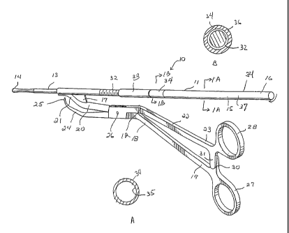
[0019] Figure 1 is a perspective view of a tenaculum-like device embodying
features of the invention.
[0020]Figure 1A is a transverse cross-sectional view of the device shown in
Figure 1 taken along the lines 1A-1A.
[0021] Figure 1 B is a transverse cross-sectional view of the device shown in
Figure 1 taken along the lines 1 B-1 B.
[0022] Figure 2 is a perspective view of a tenaculum-like device similar to
that
shown in Figure 1 with removable handles.
[0023] Figure 3 illustrates a tenaculum-like device as shown in Figure 1 with
a
uterine artery occlusion clamp mounted on the guide rail of the tenaculum-like
device.
[0024] Figure 4 is a perspective view of another embodiment of a tenaculum
like device embodying features of the invention with the tissue grasping
element in a disengaged configuration.
7
CA 02506447 2005-05-17
WO 2004/045430 PCT/US2003/037028
[0025] Figure 5 is a longitudinal cross-sectional view of the tenaculum-like
device illustrated in Figure 4 taken along line 5-5.
[0026] Figure 6 is a perspective view of the tenaculum-like device shown in
Figure 4 with the tissue grasping element in a tissue engaged configuration.
[0027] Figure 6A is a transverse cross-sectional view of the tenaculum-like
device illustrated in Figure 6 taken along line 6A-6A.
[0028] Figure 7 is a perspective view of a tenaculum-like device as shown in
Figure 4 after separation of a distal portion from a proximal portion.
[0029] Figure 8 illustrates a tenaculum-like device as shown in Figure 4 with
a
uterine artery occlusion clamp mounted on the guide rail of the tenaculum-like
device.
[0030] Figure 9 is a schematic diagram of a reproductive system of a human
female illustrating the placement of a tenaculum-like device embodying
features of the invention partially disposed within the cervical os of a
female
human patient.
DETAILED DESCRIPTION OF EMBODIMENTS OF THE INVENTION
[0031]Figure 1 illustrates a tenaculum-type device 10 embodying features of
the invention which has an elongated guide rail 11 and an attached tissue
grasping mechanism 12. The elongated guide rail 11 has a distal portion 13
with a distal tip or sound 14 and a proximal portion 15 with a free proximal
end
16 and is configured to guide a medical instrument (such as an occlusion
device shown in Figure 3) toward the distal portion of the guide rail. The
tissue grasping mechanism 12 is secured to the distal portion 13 of the guide
rail 11 by connecting plate 17 proximal to the distal tip 14 and is configured
to
8
CA 02506447 2005-05-17
WO 2004/045430 PCT/US2003/037028
grasp and stabilize the patient's uterine cervix, related tissue or near-by
anatomical structure to facilitate delivery of a medical instrument over the
guide rail to the patient's uterine cervix.
(0032]The tissue grasping mechanism 12 has a first elongated member or
handle 18 which has a proximal section 19 configured for manual
manipulation and a distal section 20 with a distal end 21 secured to
connecting plate 17. The tissue grasping mechanism 12 also has a second
elongated member or handle 22 which has a proximal section 23 configured
for manual manipulation and a distal section 24 with a tissue grasping distal
end or spike 25. The first and second elongated members 18 and 22 are
pivotally connected at a pivot 26 proximally spaced from the distal ends of
the
first and second elongated members 18 and 22. Rotation of the second
elongated member 22 about the pivot 26 adjusts the position of the tissue
grasping distal end 25 with respect to the guide rail 11 to enable the tissue
grasping distal end 25 to grasp uterine cervical tissue against the guide rail
11. In some instances the tissue grasping distal end 25 may penetrate
through the cervical wall of the patient. The proximal ends of the first and
second elongated members 17 and 22, which are configured to extend out of
the patient during the procedure, are provided with finger grips 27 and 28
respectively to facilitate manual manipulation. The proximal ends are also
provided with ratcheted locking members 30 and 31 respectively to releasably
secure the proximal ends of the elongated members 18 and 22 together.
[0033]The guide rail 11 has a threaded outer portion 32 on at least a portion
of its length and a distal collar 33 having internal lumen which allows
slidable
motion over the threaded outer portion 32 of the guide rail. A driving member
9
CA 02506447 2005-05-17
WO 2004/045430 PCT/US2003/037028
34 forms the proximal portion of the guide rail 11 and has an inner lumen 35
extending therein as shown in Figure 1A. The connecting member 36 forms
the distal end of the driving member 34 and has internal threads which mate
with the threads on the threaded outer portion 32 of the guide rail 11.
Adjusting knob 37 forms the proximal portion of the driving member 34.
Rotation of the knob 37 on the driving member 34 adjusts the position of the
distal collar 33 on the threaded outer portion 32 and thereby may drive a
treatment or diagnostic device, such as the occlusion device shown in Figure
2, to the patient's uterine cervix which is slidably mounted on the threaded
outer portion 32.
[0034]Tenaculum-like devices 10 are configured to engage other therapeutic
or diagnostic instruments such as uterine artery occlusion devices which treat
uterine disorders by applying pressure to the patient's uterine artery to
restrict
or terminate blood flow through the artery. One example of such an
instrument is uterine artery occlusion device 40 shown in Figure 2 mounted on
tenaculum like device 10. The uterine artery occlusion device 40 has
pressure-applying clamping elements 41 and 42 configured to fit on both
sides of the patient's uterine cervix and press against the patient's vaginal
fornix in order to occlude the patient's uterine arteries. Details of uterine
artery occlusion devices with pressure-applying elements are disclosed in co-
pending U.S. patent application Serial No. 10!300,116 filed on November 19,
2002, entitled "Occlusion Device with Deployable Paddles for Detection and
Occlusion of Blood Vessels" and application Serial No. 10,300,495 entitled
"Deployable Constrictor for Uterine Artery Occlusion," by Fred H. Burbank et
CA 02506447 2005-05-17
WO 2004/045430 PCT/US2003/037028
al., assigned to the present assignee Both applications are hereby
incorporated by reference in their entirety.
[0035~As shown in Figure 3, uterine artery occlusion device 40 is operatively
connected to the guide rail 11 of tenaculum-like device 10 by an attachment
sleeve 43, which is configured to at least partially surround or enclose a
portion of guide rail 11 so as to be longitudinally movable on the guide rail.
Distal sliding movement of attachment sleeve 43 moves uterine artery
occlusion device 40 along the path defined by guide rail 11. Movement of the
occlusion device 40 along the guide rail 11 may be effected manually,
mechanically (such as the drive member 33) or by other suitable means.
However, as described above, preferably the driving member 33 engages the
attachment sleeve 43 (to which the occlusion device 40 is secured) so that
rotation of the adjustable knob 36 causes movement of the occlusion device
40 along the guide rail 11.
[0036]As shown in Figure 3, the proximal portions 19 and 23 of the tissue
grasping mechanism 12 of the tenaculum-like device 10 may be configured to
be removable during use. This allows the distal portion of the tissue grasping
mechanism 12 and the guide rail to remain in the patient's vaginal canal
during the time period in which the patient's uterine arteries are being
occluding by the occluding device 40 mounted on the guide rail 11. Removal
of the proximal portions 19 and 23 provides greater comfort and freedom of
movement to a patient receiving treatment. The removable proximal portions
19 and 23 may be connected by suitable means such as a threaded
connection or with a bayonet-detent connection. to the remaining portions of
the tissue grasping members.
11
CA 02506447 2005-05-17
WO 2004/045430 PCT/US2003/037028
[0037]The tenaculum-like device 10 is inserted into the patient's vaginal
canal
and advanced therein until the distal tip 14 or sound of the guide rail 11
enters
the patient's cervical os. The distal tip 14 of the guide rail 11 is advanced
well
into the patient's cervical canal for suitable placement that will guide a
therapeutic or diagnostic device into a desired location. The tenaculum-like
device 10 may be secured in place by pressing the proximal portions 19 and
23 of the first and second elongated members so that the tissue grasping
element or spike 25 is pressed into cervical tissue. One or more spikes 25
may be disposed on the distal end of the first elongated member 18 to press
into cervical tissue in order to retain the tenaculum-like device 10 in place.
It
will be understood that other retention elements configured to retain a
tenaculum-like device 10 in place within or on a patient's body, such as
serrations, grooves, or other elements, may be employed.
[0038] Once the tenaculum-like device 10 is secured, an operator may then
manipulate the patient's uterine cervix to place the tissue in a desired
position
or orientation for a subsequent procedure such as uterine artery occlusion.
For example, by pulling on the handles 18 and 23 of the tenaculum-like device
10, the tissue next to the cervix, such as the vaginal fornix is stretched,
which
in turn pulls the uterine arteries towards the vagina so that these arteries
are
more readily compressed for occlusion. A therapeutic or diagnostic device,
such as occlusion device 40, may be attached to the guide rail 11 of
tenaculum-like device 10 either before placement of the tenaculum-like device
within a patient's vagina or it may be attached at a later time, such as after
a
tenaculum-like device 10 has been secured to the patient's cervical tissue.
12
CA 02506447 2005-05-17
WO 2004/045430 PCT/US2003/037028
[0039~An alternative tenaculum-like device 50 embodying features of the
invention is depicted in Figures 4-8. The tenaculum-like device 50 has an
elongated shaft 51 with a tissue grasping mechanism 52 on the distal portion
of the shaft. The tissue gasping mechanism 52 has an elongated arm 53 with
a tissue engaging member or spike 54 at the distal end of the arm 53. Outer
sheath member 55 is slidably disposed about a portion of the shaft 51 and is
provided with handle member 56 for advancing the sheath member over the
shaft in order for the distal end 57 of the sheath to slide over the outwardly
extending arm 53 to drive the arm toward the shaft 51 and the tissue
engaging member or spike 54 into the patient's uterine cervix 58 (which is
shown in phantom in Figures 6 and 7). The outer sheath 55 has a
longitudinally oriented slot 60 which is configured to receive the pin 61 on
the
distal portion 62 of the shaft 51. The longitudinally oriented slot 60 extends
to
the circumferentially oriented slot 63 which allows the outer sheath 55 to be
locked onto the shaft 51 with the tissue grasping element or spike 54
engaging the patient's uterine cervix 58 as shown in Figure 6. A wide variety
of other locking means may be employed to lock the spike 54 in position. The
distal portion 62 of the shaft 51 has a sound 64 with a rounded, non-traumatic
distal tip 65.
[0040~As shown in Figure 4-6 the outer sheath 55 is separated into proximal
portion 66 and distal portion 67. The distal end of the proximal portion 66
has
a semi-circular step 68 which engages the semi-circular step 70 on the
proximal end 71 of the distal portion 67 Distal thrusting and rotation of the
proximal portion 66 causes the semi-circular steps 68 and 70 to engage, drive
and rotate the proximal portion 67 so as to place the locating pin 61 on the
13
CA 02506447 2005-05-17
WO 2004/045430 PCT/US2003/037028
distal portion of the shaft 51 within the longitudinally oriented slot 60 and
ultimately into the locking circumferentially oriented slot 63. As shown more
clearly in Figure 6A, the upper surface of the distal portion 62 of the shaft
51
has a D-shaped recess 72 configured to receive the proximal end 73 of arm
53 to provide a smoother outer surFace so that when the distal end 57 of the
outer sheath 55 slides distally it slides over the arm so that the spike 54 on
the distal end of the arm engages the patient's uterine cervix. The proximal
end 73 of arm 53 disposed within the D-shaped recess 72 may be welded,
pinned, glued, or otherwise fixedly attached to shaft 14 within the recess.
The
arm 53 may be made with metal, such as stainless steel, or other durable,
flexible material, including polymers. As shown the arm 53 is formed so as to
extend radially away from the distal portion 62 of the shaft 51.
Alternatively,
the joint between the proximal end 73 of arm 53 may include a spring, or a
hinged joint, or both so as to bias the distal end of the arm having the
tissue
grasping element or spike 54 away from the shaft 51 to facilitate receiving
the
patient's uterine cervix.
(0041]As best shown in Figures 5 and 7, the elongated shaft 51 may be
formed of proximal and distal shaft sections 74 and 75 respectively which are
held together by elongated threaded member 76 which extends through the
inner lumen 77 of proximal shaft section 74 and which has a threaded distal
end 78 which is threadably connected to the threaded proximal end 80 of
distal shaft section 75. The distal end of the proximal shaft section 74 is
provided with an inner shoulder 81 which receives the proximal end 80 of the
distal shaft section 74. Clockwise rotation of the enlarged knurled end 82 of
14
CA 02506447 2005-05-17
WO 2004/045430 PCT/US2003/037028
the threaded member 76 tightens the connection between the proximal and
distal shaft sections 74 and 75.
[0042]Once the tenaculum-like device 50 and any device delivered by the
tenaculum like device has been intravaginally deployed with the tissue
grasping mechanism 52 locked in place, the proximal shaft section 74 and the
proximal portion 66 of the of the outer sheath 55 may be detached by rotating
the enlarged knurled end 82 in a counter clockwise direction to unscrew the
threaded member 76 from the proximal end of the distal shaft section 75,
leaving the distal shaft section and the distal portion 67 of the outer sheath
55
so that any device mounted on the tenaculum-like device 10 remains engaged
with a cervix 58. This disengagement eliminates the proximal portion of the
tenaculum-like device 10 from extending out of a patient's vagina and the
accompanying discomfort and inconvenience during a procedure. At the end
of the procedure the proximal portion 66 of the outer sheath 55 may be re-
engaged with the proximal end of the distal portion 56 of the sheath 55 to
unlock the tissue grasping mechanism 12 so that the remainder of the
tenaculum-like device 10 and any treatment or diagnostic device still attached
to be removed from the patient.
[0043] Figure 8 illustrates a uterine artery occlusion device 85, described in
detail in copending application Serial No. 10/300,116, secured to the distal
portion of the tenaculum-like device 50. The paddle-like members 86 and 87
are configured to engage both sides of the patient's uterine cervix to occlude
both uterine arteries. The occlusion device 85 may be advanced over the
tenaculum-like device 50 manually or in a manner similar to that shown in the
previously discussed embodiment shown in Figures 1-3.
CA 02506447 2005-05-17
WO 2004/045430 PCT/US2003/037028
[0044]A schematic diagram of female human reproductive anatomy and
related structures is shown in Figure 9, illustrating the placement and use
therein of tenaculum-like device 50 previously described. The anatomical
features shown in Figure 9 include uterus 90, vaginal canal 91, uterine cervix
92, vaginal fornix 93, cervical os 94, and uterine arteries 95 and 96 (which
provide a large fraction of the uterine blood supply). A uterine fibroid 97
within
the uterine wall is also illustrated. As discussed above, and as disclosed in
U.S. application serial number 09/908,815, filed July 20, 2001, to Burbank et
al. ("'815 application"), co-assigned with the present application, the entire
contents of which are incorporated by reference herein, reduction or
termination of blood flow in the uterine arteries is effective to treat
uterine
fibroids and other disorders of a female patient's uterus. The uterus 90 is
accessed via vaginal canal 91 and through uterine cervix 92. The vaginal
canal 91 has a wall forming the vaginal fornix 93 adjacent uterine cervix 92.
The sound 64 extends through the cervical os 94 into the cervical canal 97.
Arm 53 is pressed toward the sound 64 so that the spike 54 engages the
exterior of uterine cervix 92. With the uterine cervix firmly secured, the
tenaculum-type device may be employed to adjust the position of the cervix to
facilitate the advancement of medical instruments over the shaft of the
tenaculum-like device 50 to the uterus. The uterus 90 is supplied with blood
predominantly by the uterine arteries 95 and 96 with lesser amounts coming
from the patient's ovarian arteries. By advancing the uterine artery occlusion
device such as that shown in Figure 8 (or Figure 2), to press the paddles
thereof against the patient's vaginal fornix, the underlying uterine arteries
may
be occluded when the paddles are close and locked in position.
16
CA 02506447 2005-05-17
WO 2004/045430 PCT/US2003/037028
[0045] The uterine cervical canal of a woman who has not given birth is
usually tight enough to firmly hold the sound of the tenaculum-type device
embodying features of this invention within the canal with the tissue grasping
mechanism engaged with the patient's uterine cervix. However, the uterine
cervical canal of a woman who has given birth is frequently too dilated to
effectively retain the sound within the patient's uterus even with the tissue
grasping mechanism engaged with the cervical tissue. For these situations,
as shown in Figure 10, the sound 100 may be expanded to provide a more
snug fit within the patient's cervical canal. The curvatures R~ and R2 of the
expanded bifurcated portions 101 and 102 of the sound 100 may be varied to
provide the desired expansion for effective retention of the sound portions
101
and 102. The bifurcated sound portions 101 and 102 may be held together
mechanically or otherwise in an unexpended condition to facilitate insertion
into the patient cervical os. However, once the bifurcated sections 101 and
102 are disposed well within the patient's cervical canal, the restraint used
to
hold the bifurcated sections together can be removed to allow the expansion
of the bifurcated structure. A circular collar 103 may be moved distally along
the shaft of the tenaculum type device to close the expanding sound portions
101 and 102. Once the sound 100 is in position within the patient's cervical
canal, the restraint collar 103 may be proximally withdrawn from the sound
100 to allow the expansion of the sound portions 101 and 102. The
expandable sound 100 may be used in either the embodiment shown in
Figures 1-3 and the embodiment shown in Figures 4-8, previously described.
[0046] While particular forms of the invention have been illustrated and
described, it will be apparent that various modifications can be made without
17
CA 02506447 2005-05-17
WO 2004/045430 PCT/US2003/037028
departing from the spirit and scope of the invention. Accordingly, the
invention is not to be limited to the specific embodiments illustrated, but is
to
be defined by the scope of the appended claims as broadly as the prior art
will
permit, and in view of the specification if need be. Moreover, those skilled
in
the art will recognize that features shown in one embodiment may be utilized
in other embodiments. Terms such as "element", "member", "device",
"section", "portion", "step", "means" and words of similar import when used in
the following claims shall not be construed as invoking the provisions of 35
U.S.C. ~112(6) unless the claims expressly use the terms "means" or "step"
followed by a particular function without setting forth specific structure (in
the
case of "means") or action (in the case of "step"). All patents and patent
applications referred to above are hereby incorporated by reference in their
entirety.
l~