Note: Descriptions are shown in the official language in which they were submitted.
CA 02506461 2005-05-16
WO 2004/064674 PCT/US2004/001443
1
MOBILE BEARING PATELLAR PROSTHESIS
WITH ORBITAL TRANSLATION
Technical Field
The present invention relates to a prosthetic patello-femoral joint assembly
and, more
particularly, to a mobile bearing patellar prosthesis with orbital translation
such that the
articulation component moves in an infinite number of directions with respect
to the baseplate.
Background Art
In the United States alone, over 200,000 knee replacements are performed each
year.
Degenerative arthritis, or the gradual degeneration of the knee joint, is the
most common
reason for these replacements. In this form or arthritis, cartilage and
synovium surrounding
the knee wear down so underlying bones grind directly on each other.
In knee arthroplasty, portions of the natural knee joint are replaced with
prosthetic
components. These components include a tibial component, a femoral component,
and a
patellar component. The femoral component generally includes a pair of spaced
condyles that
articulate with the tibial component. These condyles form a trochlear groove
in which the
articulating surface of the patellar component moves. The components are made
of materials
that exhibit a low coefficient of friction when they articulate against one
another.
When the articulating ends of both the femur and tibia are replaced, the
procedure is
referred to as total knee replacement or TKR. Much effort has been devoted to
performing
TKR that restores normal, pain-free functions of the knee for the lifetime of
the prosthetic
components.
Unfortunately, patients can experience problems with the prosthetic knee after
a total
knee replacement surgery. If a problem occurs, a patient may need a revision
surgery wherein
some or all of the prosthetic components are replaced. Historically, problems
associated with
the patellar prosthesis are responsible for as many as 50% of all knee implant
revisions. More
particularly, complications with the patello-femoral joint or patello-femoral
dysfunction are
the primary cause of failure in TIER.
One option in a TIER or revision surgery is to implant a prosthetic patellar
component.
The patellar component has a metallic back or baseplate that is permanently
fixed to the
CA 02506461 2005-05-16
WO 2004/064674 PCT/US2004/001443
2
patellar bone. Metal baseplates were introduced to provide a more even stress
distribution on
the natural patella and provide the option for either cement or cementless
fixation. An
articulation or bearing component is permanently connected to the baseplate to
form the
prosthetic patellar component. The articulation component is formed from metal
or a polymer,
such as ultra-high molecular weight polyethylene (UHMWPE).
Typically, the articulation component can move relative to the baseplate. This
movement is extremely important to the success and proper fiulction of the
prosthetic patella.
As a normal knee proceeds through a full range of flexion, the patella
actually moves in
several directions as it tracks along the trochlear groove. Even under normal
motion, for
example, the patella can move both medially and laterally, with the actual
movement of the
patella having a much more complicated pathway. Not surprisingly then, much
effort has been
devoted to designing a prosthetic patella that emulates the movement of a
natural patella.
United States patent number 5,702,465 entitled "Patella Prosthesis Having
Rotational
and Translational Freedom" to Burkinshaw teaches a two-piece prosthetic
patella in which the
articulation component moves in two different directions with respect to the
baseplate.
Specifically, the articulation component can rotate about the baseplate and
move vertically in a
longitudinal channel in the baseplate. United States patent number 5,609,644
entitled
"Prosthetic Patello Femoral Joint Assembly" to Ashby et al. teaches a two-
piece prosthetic
patella in which the articulation component moves in three different
directions with respect to
the baseplate. Specifically, the articulation component can rotate about the
baseplate and
move vertically in a longitudinal channel in a manner somewhat similar to USPN
5,702,465.
The design in Ashby, though, allows for a small ,amount of medial-lateral
shift while the
articulation component tracks along the longitudinal groove.
Despite current advances in the design of the connection between the
articulation
component and the baseplate, prosthetic patellae still do not fully emulate
the natural
movement of the patella. Specifically, these prior designs limit the movement
of the
articulation component with respect to the baseplate. Typically, these
movements occur in
straight, axial directions, such as movement down a longitudinal channel or
movement in a
purely medial-lateral direction while in this channel.
It, therefore, would be advantageous to provide an implantable patellar
prosthesis that
could closely emulate the natural movement of a patella. This prosthesis would
have an
CA 02506461 2005-05-16
WO 2004/064674 PCT/US2004/001443
3
articulation component that could move in an infinite number of directions
with respect to the
baseplate.
Disclosure of Invention
The present invention relates to a prosthetic patello-femoral joint assembly
used to
replace a portion of the natural knee and, more particularly, to a mobile
bearing patellar
prosthesis with orbital translation such that the articulation component moves
in an infinite
number of directions with respect to the baseplate. The patellar prosthesis
comprises two basic
components: A baseplate and an articulation component.
Each baseplate has a fixation surface and a bearing surface. The fixation
surface is
adapted to engage patellar bone and includes a plurality of pegs that extend
outwardly from
the surface to penetrate bone. The bearing surface connects to the
articulation component as
described herein.
Each articulation component has an articulation surface and a bearing surface.
The
articulation surface has a smooth contour that is adapted to articulate with a
femoral
component, such as a natural femur or femoral prosthesis at the patello-
femoral joint. This
surface may have various shapes known to those skilled in the art, such as a
hyperbolic
paraboloid, saddle-shape, or dome-like configuration. The bearing surface of
the articulation
component is adapted to engage the bearing surface of the baseplate. These
surfaces are
configured to lock together and then slideably contact or articulate with each
other.
An attachment mechanism couples the baseplate to the articulation component so
the
bearing surfaces are adj acent each other. The attachment mechanism can have a
variety of
configurations to enable the articulation component to engage and articulate
with the
baseplate. In one embodiment, this mechanism includes an attachment member
that protrudes
from the bearing surface of the baseplate. The attachment member has a
cylindrical shaft with
an enlarged head. This head has a circular body portion with two wings that
extend from
opposite ends of the circular body. The articulation component includes a
recess or keyway
shaped to receive the enlarged head of the attachment member. This recess
extends into the
body of the articulation component and includes an undercut.
In operation, the head of the attachment member is inserted into the recess in
the
articulation component. The articulation component is then rotated so the
wings of the head
CA 02506461 2005-05-16
WO 2004/064674 PCT/US2004/001443
4
extend along the undercut. In this position, the articulation component and
baseplate are
engaged and locked together since the wings are captured inside the undercut.
As one important advantage of the present invention, the articulation
component can
move in an infinite number of directions with respect to the baseplate.
Specifically, the
diameter of the head of the attachment member (as measured from the ends of
the wings) is
less than the diameter of the bearing surface of the articulation component
but greater than an
inner diameter of the undercut. In other words, while the articulation
component remains
captured to the baseplate, the wings of the attachment member do not
completely extend the
full distance into the undercut. This difference in distance enables the
articulation component
to move while engaged and captured to the baseplate. Most importantly, the
movement of the
articulation component with respect to the baseplate is not limited to one or
two axial
directions. Instead, the articulation component can freely move in the X-Y
plane in an infinite
number of directions with respect to the baseplate. This movement can occur in
a circular
pathway along the undercuts. As such, the articulation component has "orbital
translation"
with respect to the baseplate.
As another advantage of the present invention, the articulation component is
removeably connectable to the baseplate. In other words, even after the
baseplate becomes
permanently connected to the patellax bone, an articulation component can be
readily attached
or detached from the baseplate. During a revision surgery then, healthy bone
stock of the
natural patella will not be damaged or removed since the baseplate can be left
attached to the
patella.
As yet another advantage, the attachment mechanism of the patellar prosthesis
can be
utilized with various designs of articulation components and baseplates. In
one embodiment,
for example, the patellar prosthesis comprises only two separate or individual
components: A
base component and an articulation component. No other components are required
to form
and connect the patellar prosthesis with orbital translation. Both the
articulation component
and the baseplate are formed as a single unit or piece. In other words, these
components are
not formed from multiple pieces assembled together, but from a unitary,
integral unit or piece.
Further, these two components include an attachment mechanism that is
integrally formed to
either or both components. As such, no separate attachment mechanism is
required to couple
the baseplate and articulation component. In another embodiment, a third or
intermediate
component is used to connect the articulation component and baseplate. This
third component
CA 02506461 2005-05-16
WO 2004/064674 PCT/US2004/001443
forms the bearing surface of the articulation component and houses a portion
of the attachment
mechanism needed to engage with the baseplate.
Other objects and advantages of the present invention will be apparent from
the
following descriptions of a preferred embodiment with reference to the
drawings.
5 Brief Description of Drawings
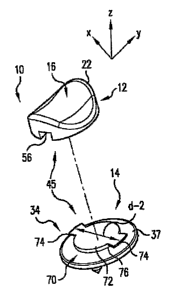
FIG. 1 is an exploded top perspective view of a two-piece patellar prosthesis
of the
present invention.
FIG. 2 is an exploded side view of the patellar prosthesis of FIG. 1.
FIG. 3 is an exploded bottom perspective view of the patellar prosthesis of
FIG. 1:
FIG. 4 is an exploded top perspective view of a three-piece patellar
prosthesis of the
present invention.
FIG. 5 is an exploded side view of the patellar prosthesis of FIG. 4.
FIG. 6 is a bottom view of each component of the three-piece patellar
prosthesis of
FIG. 4.
FIG. 7 is a top view of each component of the three-piece patellar prosthesis
of FIG. 4.
Best Mode for Carrying Out the Invention
FIGS. 1-3 show a prosthetic patello-femoral joint assembly or mobile bearing
patellar
prosthesis 10 used to replace a portion of the natural knee. The patellar
prosthesis comprises
two basic components: An articulation component 12 and a baseplate 14.
The articulation component and baseplate are shown relative to mutually
orthogonal
reference axes X, Y and Z (FIG. 1). When a prosthesis is implanted, reference
axes X, Y and
Z correspond, generally, to well known and accepted anatomical directional
terms. The X axis
extends generally in the medial-lateral direction, the Y axis extends
generally in the inferior-
superior direction, and the Z axis extends generally in the posterior-anterior
direction. If the
prosthesis were implanted on the left patella of a human patient, the ends of
each of the X, Y,
and Z axes marked with an arrowhead would point generally in the medial,
superior, and
posterior directions, respectively. Further, the X and Y axes together form an
X-Y plane.
The present invention may be utilized in various surgical techniques known to
those
skilled in the art. As an example, during a TKR surgery, the patella is
resected in a plane
CA 02506461 2005-05-16
WO 2004/064674 PCT/US2004/001443
6
generally perpendicular to the anterior-posterior direction to remove a
posterior portion of the
patellar bone, leaving a resected planar bony surface. When a prosthesis is
implanted, the Z
axis lies perpendicular to the resected planar bony surface of a patella, and
the X and Y axes
lie parallel to the resected planar bony surface.
Articulation component 12 is constructed of a biocompatible material having
desirable
wear and bearing friction properties, such as biocompatible metals and ultra-
high molecular
weight polyethylene (UHMWPE). Examples of suitable materials are Metasul~ and
Durasul~ articulation components manufactured by Centerpulse Orthopedics Inc.
of Austin,
Texas.
Articulation component 12 includes two primary surfaces: An articulation
surface 16
and a planar bearing surface 18 oppositely disposed from the articulation
surface. The bearing
surface 18 is generally perpendicular to the Z axis and spaced from the
articulation surface 16
to define a thickness. A wall 20 extends around the outer perimeter of the
articulation
component and generally has an elliptical or round shape.
Articulation surface 16, in the preferred embodiment shown, is a hyperbolic
paraboloid, also known as a "saddle" shape, in which the intersection of the
surface 16 and
wall 20 defines an undulating edge 22. Articulation surface 16, so configured,
ideally
provides congruent sliding contact over an extensive range of articulation
between articulation
component 12 and the patellar articulation surface of a femoral component,
such as the natural
femur or a femoral prosthetic component at the patello-femoral joint.
Baseplate 14 is constructed of a biocompatible material having desirable wear,
bearing
friction, and bone engaging properties that are known to those skilled in the
art. Examples of
such a material are UHMWPE, titanium, titanium alloys, ceramics, aluminum
oxide ceramics,
and cobalt chromium alloys.
Baseplate 14 includes a fixation surface 32 for engaging patellar bone, a
planar bearing
surface 34 generally perpendicular to the Z axis and spaced from the fixation
surface 32, and
an outer wall 36 that extends around the perimeter and is generally parallel
to the Z axis. The
baseplate generally has an elliptical or round shape to match the size and
shape of the
articulation component 12. Bearing surface includes a convex surface portion
37 that extends
around with a ring shape.
Fixation surface 32 includes a generally planar surface portion 38 adapted to
engage
resected planar bony surface 13 generally parallel thereto. The surface
portion 38 can be
CA 02506461 2005-05-16
WO 2004/064674 PCT/US2004/001443
7
adapted to directly engage and integrate with the patellar bone with or
without bone cement.
Planar surface portion 38, for example, can include surface texturing to
promote
osseointegration of baseplate 14. A coating of hydroxyapatite, ceramic, or
porous metal are
examples of surface texturing known to those skilled in the art. Such coatings
can be applied
with plasma spraying or sintering techniques. Suitable metals for sintering
include titanium
and its alloys and cobalt chromium alloys. Other materials and methods for
providing a
surface that favors osseointegration are well known in the art.
Fixation surface 32 also includes a plurality of pins or pegs 40 that extend
downward
from the surface. These pegs are evenly and symmetrically spaced apart and are
integrally
connected to fixation surface 32. The pegs 40 are sized and shaped to be
received in
correspondingly shaped bores (not shown) in the patella. Specifically, each
peg has a
cylindrical body portion with a tapered or conical distal end. One skilled in
the art will
appreciate that the pegs can have various configurations and textures, such as
a straight,
ribbed, or tapered shape with macro-textured surface to enhance fixation with
bone cement or
osseointegration.
The articulation component 12 is removeably connectable to the baseplate 14.
Even
after the baseplate becomes permanently connected to the patellar bone, an
articulation
component can be readily or easily attached and detached from the baseplate.
The removeable
or detachable connection between the baseplate and articulation component
provides a
modular patellar prosthesis.
A coupling or attachment mechanism 45 located on the bearings surfaces of both
components enables the articulation component 12 and baseplate 14 to be
connectable to and
removeable from each other.
On the bearing surface 18 of the articulation component, the attachment
mechanism
includes a keyway or recess 52 having a circular or elliptical center portion
54 with two
rectangular slots 56 oppositely disposed from each other. Recess 52 does not
cover the entire
surface, but leaves two outer or bottom walls 58. These walls have a concave
angulation to
exactly match the convex angulation of the convex surface portion 37 on the
bearing surface
34 of the baseplate 14. Further, these walls form an undercut 60 with bottom
wall 62. This
undercut is circular and extends around the periphery of articulation
component 12 and
adjacent to outer wall 20.
CA 02506461 2005-05-16
WO 2004/064674 PCT/US2004/001443
8
On the bearing surface 34 of the baseplate 14, the attachment mechanism
includes an
attachment member 70. This attachment mechanism has a disc-shaped body 72 with
a pair of
oppositely disposed, rectangular wings 74. These wings extend outwardly from
the disc-
shaped body and form an undercut 76 beneath themselves.
It should be noted that body 72 may have a circular or elliptical shape. An
elliptical
shape provides a controlled amount of orbital translation as the articulation
component moves
relative to the baseplate.
In order to engage or connect the articulation component 12 to the baseplate
14,
attachment member 70 is positioned into recess 52 such that disc-shaped body
72 and wings
74 fit into center portion 54 and slots 56, respectively. The articulation,
component is then
rotated in a clockwise or counterclockwise direction to lock the articulation
component to the
baseplate. Once locked together, the wings 74 can freely rotate along and
inside the undercut
60. Walls 58 prevent the wings from disengaging from the undercut and, thus,
prevent the
articulation component from disengaging with the baseplate.
In order to remove the articulation component 12 from the baseplate 14, the
articulation component is rotated so wings 74 of attachment member 30 are
positioned in slots
56 of recess 52. The articulation component is then pulled or removed from the
baseplate.
One skilled in the art will appreciate that attachment mechanism can be
altered without
departing from the scope of the invention. As an example, the coupling
components on the
articulation component and baseplate can be switched: The articulation
component could be
configured to have a protruding attachment member while the baseplate has a
matching recess
adapted to receive, engage, and lock with the attachment member. Other
embodiments as well
are within the scope of the invention, and FIGS. 4-7 show one such embodiment.
FIGS. 4-7 show a patellar prosthesis 100 configured similarly to the patellar
prosthesis
10 of FIGS. 1-3, with several differences. The attachment mechanism is formed,
in part, using
a third component 102 separate and distinct from the articulation component
112 and baseplate
114. As another difference, the bearing surface 134 of baseplate 114 has a
concave surface
portion 137 (shown as a convex surface portion 37 in FIGS. 1 and 2). As yet
another
difference, the articulation component 112 includes a peripheral surface 117
with two
rectangular recesses 119 that extend into surface 117 and partially around the
periphery.
These recesses include a lip or shoulder 121.
CA 02506461 2005-05-16
WO 2004/064674 PCT/US2004/001443
9
Component 102 includes a top surface 120 and a bottom surface 122. Two wings
123
extend upwardly from top surface 120. These wings are oppositely disposed and
have a
curved, rectangular shape. A lip or shoulder 124 is provided at a distal end
of each wing.
The bottom surface 122 includes a keyway or recess 152 having a circular or
elliptical
center portion 154 with two rectangular or winged slots 156 oppositely
disposed from each
other. Recess 152 does not cover the entire surface, but leaves two outer or
bottom walls 158.
These walls have a convex angulation to exactly match a concave angulation of
the concave
surface portion 137 of on the bearing surface 134 of the baseplate 114.
Further, these walls
form an undercut 160 with bottom wall 162. This undercut is circular and
extends around the
periphery of third component 10.2 and adjacent to outer wall 141.
In order to connect the third component 102 to the articulation component 112,
the top
surface 120 is pushed against the underside of the articulation component
until the wings 123
extend into recesses 119. As the wings are pushed upwardly, they expand
radially and the
shoulders .124 snap over lips 121 to lockingly engage the third component 102
to the
articulation component 112. Once connected, the bottom surface 122 of the
third component
now becomes the bearing surface of the articulation component 112. The
attachment between
these two components can be designed to be non-removeable (i.e., permanent) or
removeable.
Once the third component 102 is connected to the articulation component 112,
the
articulation component and baseplate connect, engage, and disengage in a
manner similar to
the articulation component 12 and baseplate 14 described in connection with
FIGS. 1-3.
One important advantage of the present invention is that the articulation
component
can move in an infinite number of directions in the X-Y plane (FIG. 1 ) with
respect to the
baseplate. Reference should be made to the figures. Specifically, the diameter
"d-2" (FIG. 1)
of the top surface of the disc-shaped body 72 of attachment member 70 (as
measured from the
ends of the wings 74) is less than the diameter "d-1" (FIG. 2) of the bearing
surface 18 of the
articulation component 12. In other words, while the articulation component
remains captured
to the baseplate, the wings 74 of the attachment member 70 do not completely
extend the full
distance into the undercuts 60. This difference in distance enables the
articulation component
to move while engaged and captured to the baseplate. The amount of movement is
equal to
"d-1" minus "d-2." Most importantly, the movement of the articulation
component with
respect to the baseplate is not limited to one or two axial directions.
Instead, the articulation
component can move in the X-Y plane (FIG. 1 ) in an unlimited or infinite
number of
CA 02506461 2005-05-16
WO 2004/064674 PCT/US2004/001443
directions with respect to the baseplate. In other words, the articulation
component can move
along the X axis (i.e., in both the medial and lateral directions), along the
Y axis (i.e., in both
the inferior and superior directions), and along all directions within the X-Y
plane (including
directions that are not parallel with the X and Y axes). This movement can
occur in a circular
5 pathway along the undercuts 60 formed in the articulation component. As
such, the
articulation component has "orbital translation" with respect to the
baseplate. It is important
to note that this orbital translation is different than rotational
translation. While the
articulation component 12 is connected to the baseplate 14, the articulation
component can
rotate about the attachment member 70. This rotation occurs around the Z-axis
(FIG. 1) and is
10 in addition to the orbital translation in the X-Y plane.
It should be noted that "d-1" defines the major diameter of the bearing
surface of the
articulation component. Even though the length "d-1" is greater than "d-2,"
the articulation
component cannot disengage from the baseplate until the wings 74 are aligned
in the recesses
56. Specifically, walls 58 form an inner diameter that is greater than "d-2."
As such, these
walls 58 keep the wings engaged in the undercuts 60. The length of "d-2"
should be designed
to be greater than the inner diameter but less than the outer diameter of the
bearing surface of
the articulation component.
When the articulation component is connected to the baseplate, the bearing
surfaces of
each component lie in direct engagement with each other. These surfaces can
slideably
engage or articulate in a rotational manner about the Z-axis and in an orbital
translation or
infinite number of directions in the X-Y plane.
This orbital translation works equally well with the embodiment shown in FIGS.
4-7.
FIGS. 6 and 7 illustrate the diameters "d-1" and "d-2" as discussed in
connection with FIGS.
1-3.
As another advantage of the present invention, the bearings surfaces of the
articulation
component and baseplate have mating convex and concave surfaces. Specifically,
FIGS. 1-3
show bearing surface 34 with a convex surface portion 37 and bearing surface
18 with a
concave wall 58; and FIGS. 4-7 show a concave surface portion 137 on baseplate
114 and
convex walls 158 on articulation component 112. These surfaces enable the
patellar prosthesis
to more closely emulate the natural movement of the patella as the
articulation component
slideably engages the baseplate.
CA 02506461 2005-05-16
WO 2004/064674 PCT/US2004/001443
11
Although illustrative embodiments have been shown and described, a wide range
of
modifications, changes, and substitutions is contemplated in the foregoing
disclosure and in
some instances, some features of the embodiments may be employed without a
corresponding
use of other features. Accordingly, it is appropriate that the appended claims
be construed
broadly and in a manner consistent with the scope of the embodiments disclosed
herein.