Note: Descriptions are shown in the official language in which they were submitted.
_. .. ... w,... i .. ._. ,,,
CA 02506612 2008-07-17
WO 2004/048685 PCT/3E2003/001769
APPARATUS AND METHOD FOR DEWATERING A PAPER WEB
AND RECIRCULATING EXHAUST AIR
BACKGROUND OF THE INVENTION
Field of the Invention
The present invention relates to papermaking machines and, more particularly,
to papermaking machine configured to selectively recirculate exhaust air from
a dryer
so as to increase dewatering efficiency in processes upstream of the dryer, to
reduce
emissions from the papermaking machine, and to enhance a vacuum system
associated with the papennaking machine.
Description of Related Art
Drying devices such as, for example, through-air dryers and Yankee dryers,
are often employed in papermaking machines for drying a paper web after the
paper
web has been formed. Such drying devices often use a combination of heat and
flowing air to dry the paper web and, as such, the exhaust from such drying
devices
comprises moisture-laden hot air. Generally, the venting of the exhaust from a
drying
device to atmosphere is undesirable for several reasons. For example, venting
of the
hot, moisture-laden air releases thermal energy that could be applied to other
processes within the papermaking machine. Further, releasing the hot, moisture-
laden
air may increase undesirable papermaking plant emissions and may be
unfavorably
received by or may adversely affect neighbors surrounding the papermaking
plant. In
addition, significant and continuous environmental testing associated with the
emissions may also be required. Accordingly, it would be desirable to reduce,
minimize, or eliminate the emission of exhaust from such papermaking machine
drying devices.
In some instances, the papermaking machine may be configured such that the
exhaust from the drying device is recirculated through the drying device in
order to
reduce the heat input necessary to provide the heated air to the drying
device, as well
as to reduce emissions. In other instances, some of the exhaust from the
drying
device may be used to reduce process heat demands or to heat buildings.
However,
-1-
CA 02506612 2005-05-18
WO 2004/048685 PCT/SE2003/001769
the heat from the exhaust of the drying devices often exceeds the amount of
heat that
can practically be re-used. In addition, a certain amount of the exhaust from
the
drying device must often be diverted so as to, for instance, remove excess
condensates
from the exhaust, wherein the exhaust may then be recirculated through the
drying
device. In such instances, though, the diverted portion may still be vented to
atmosphere and thus will continue to undesirably contribute to plant
emissions.
In order to reduce the amount of moisture to be removed from the web by the
drying devices, many papermaking machines employ vacuum devices prior to the
drying devices for partially dewatering the web. However, for example, in
papermaking machines employing through-air dryers, it often undesirable to
press or
compact the web, though the web must still be dewatered to, for instance,
about 18%
to about 32% dryness. The vacuum devices thus employed to provide the
necessary
vacuum for dewatering the web to such an extent, and without pressing the web,
often
undesirably consume a significant amount of energy.
Thus, there exists a need for a papermaking machine having reduced
emissions from the exhaust of the drying device(s). Further, it would be
desirable for
such a papermaking machine to have an efficient non-compacting (in the case of
a
machine employing a through-air dryer) dewatering process before the web is
directed
through the drying device(s). In addition, it would be desirable for the
papermaking
machine to exhibit reduced energy consumption with respect to the vacuum
system
and/or other high energy-consumption systems associated with the machine.
BRIEF SUMMARY OF THE INVENTION
The above and other needs are met by the present invention which, in one
embodiment, provides an apparatus for decreasing heat emission and enhancing a
vacuum system in a papermaking machine. Such an apparatus includes a drying
device configured to dry a paper web, wherein the drying device has an air
inlet for
receiving heated air for removing moisture from the web and an air outlet for
exhausting the moisture-containing air from the drying device. A vacuum system
is
configured to produce a suction and to receive the moisture-containing air. A
web
handling device is disposed upstream of the drying device and is configured to
interact with the web before the web is directed to the drying device. The web
handling device is further configured to receive a portion of the moisture-
containing
-2-
CA 02506612 2005-05-18
WO 2004/048685 PCT/SE2003/001769
air from the air outlet of the drying device, wherein the portion of the
moisture-
containing air is directed through the web by the web handling device so as to
facilitate dewatering of the web before the moisture-containing air is
received by the
vacuum system. The web handling device is also configured to provide the
moisture-
containing air at a supply pressure with respect to the suction produced by
the vacuum
system such that the web handling device operates at an above-ambient
pressure.
Another advantageous aspect of the present invention comprises a method of
decreasing heat emission and enhancing a vacuum system in a papermaking
machine.
The papermaking machine includes a drying device configured to dry a paper
web,
wherein the drying device has an air inlet for receiving heated air for
removing
moisture from the web and an air outlet for exhausting the moisture-containing
air
from the drying device, a web handling device disposed upstream of the drying
device
and configured to interact with the web before the web is directed to the
drying
device, and a vacuum system for producing a vacuum. A portion of the moisture-
containing air from the air outlet of the drying device is directed to the web
handling
device, and through the web to the vacuum system, at a supply pressure with
respect
to the suction produced by the vacuum system such that the web handling device
operates at an above-ambient pressure, so as to facilitate dewatering of the
web.
Still another advantageous aspect of the present invention comprises an
apparatus for increasing dewatering efficiency of a paper web in a papermaking
machine. Such an apparatus includes a drying device configured to dry the web,
wherein the drying device has an air inlet for receiving heated air for
removing
moisture from the web and an air outlet for exhausting the moisture-containing
air
from the drying device. An air handling device has an air inlet for receiving
incoming
air to be heated and an air outlet in communication with the air inlet of the
drying
device for directing the heated air thereto. A web handling device is disposed
upstream of the drying device and is configured to interact with the web
before the
web is directed to the drying device. The web handling device is configured to
receive a mixture of a portion of the heated air from the air outlet from the
air
handling device and a portion of the moisture-containing from the air outlet
from the
drying device for facilitating dewatering of the web, wherein the web handling
device
is further configured to interact with the web at an above-ambient pressure.
-3-
CA 02506612 2005-05-18
WO 2004/048685 PCT/SE2003/001769
Yet another advantageous aspect of the present invention comprises a method
of increasing dewatering efficiency of a paper web in a papermaking machine.
The
papermaking machine includes a drying device configured to dry a paper web,
wherein the drying device has an air inlet for receiving heated air for
removing
moisture from the web and an air outlet for exhausting the moisture-containing
air
from the drying device. An air handling device has an air inlet for receiving
incoming
air to be heated and an air outlet for directing the heated air to the drying
device,
while a web handling device is disposed upstream of the drying device and is
configured to interact with the web before the web is directed to the drying
device.
Accordingly, a portion of the moisture-containing air is first directed from
the air
outlet of the drying device, while a portion of the heated air from the air
outlet of the
air handling device is concurrently directed to be mixed therewith, before the
mixture
of air is directed to the web handling device. Thereafter, the mixture of air
is directed
through the web at the web handling device, the web handling device being
operated
at an above-ambient pressure, so as to facilitate dewatering of the web.
Thus, embodiments of the present invention meet the above-identified needs
and provide significant advantages as detailed further herein.
BRIEF DESCRIPTION OF THE SEVERAL VIEWS OF THE DRAWING(S)
Having thus described the invention in general terms, reference will now be
made to the accompanying drawings, which are not necessarily drawn to scale,
and
wherein:
FIGS. lA-1B schematically illustrate alternative embodiments of a
papermaking machine according to the present invention;
FIG. 2 is a schematic illustration of an air circulation system showing waste
air from the drying devices being directed to upstream web handling devices,
with a
vacuum system in communication with a web handling devices, according to one
" embodiment of the present invention;
FIG. 3 is a schematic illustration of an air circulation system having a hot
air
supply device in association with a vacuum system, according to one embodiment
of
the present invention; and
FIG. 4 is a schematic illustration of a through-air dryer showing a hood
associated with the TAD extending over a vacuum box, with a blower extending
into
-4-
CA 02506612 2005-05-18
WO 2004/048685 PCT/SE2003/001769
the hood opposite to the vacuum box, according to one embodiment of the
present
invention; and
FIG. 5 is a schematic illustration of air circulation system showing a mixture
of waste air from the drying devices and fresh hot air from an air handling
device
being directed to upstream web handling devices, with a vacuum system in
communication with a web handling devices, according to one embodiment of the
present invention.
DETAILED DESCRIPTION OF THE INVENTION
The present inventions now will be described more fully hereinafter with
reference to the accompanying drawings, in which some, but not all embodiments
of
the invention are shown. Indeed, these inventions may be embodied in many
different
forms and should not be construed as limited to the embodiments set forth
herein;
rather, these embodiments are provided so that this disclosure will satisfy
applicable
legal requirements. Like numbers refer to like elements throughout.
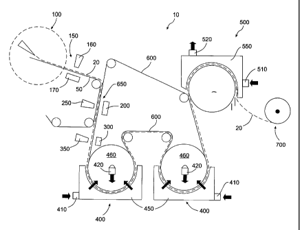
FIGS. 1A - IB illustrates an example of a papermaking machine according to
one embodiment of the present invention, the papermaking machine being
indicated
generally by the numeral 10. Such a machine 10 includes a former 100 for
forming a
paper web 20 on a forming fabric 50. Such a machine 10 further comprises one
or
more drying devices such as, for example, an impingement dryer (not shown), a
through-air dryer 400, and/or a Yankee dryer 500. The drying devices generally
include a drying fabric 600 configured to receive the web 20 from the forming
fabric
50 and to transport the web 20 through the through-air dryer(s) 400 to the
Yankee
dryer 500. In some embodiments, the drying fabric 600 may also comprise the
forming fabric 50 in that the web 20 may be formed directly on the drying
fabric 600,
which may eliminate the forming fabric 50. At the Yankee dryer 500, the web 20
is
separated from the drying fabric 600, dried by the Yankee dryer 500, creped
from the
Yankee dryer 500, and then directed to a reel-up 700. Note, however, that some
embodiments may not include a Yankee dryer 500.
Generally, the web 20 may be dewatered, transferred between fabrics at
various points between the former 100 and the drying devices, and otherwise
handled
by one or more various web handling devices 75. For example, after the web 20
is
formed on the forming fabric 50 by the former 100, the web 20 may be directed
-5-
CA 02506612 2008-01-24
through a hot air supply device 150 for dewatering the web 20. In some
instances,
where the web 20 is transferred from the forming fabric 50 to the drying
fabric 600, a
vacuum box 200 may be provided for facilitating transfer of the web 20 to the
drying
fabric 600. In still other instances, a molding box 300 may be disposed prior
to the
drying devices to structure the web 20, to provide additional dewatering of
the web
20, to pre-heat the web 20 prior to the web 20 entering the drying device,
and/or, for
example, to provide a seal arrangement for a drying device as discussed, for
example,
in U.S. Patent No. 6,199,296, also assigned to the assignee of the present
invention.
One skilled in the art will
appreciate, however, that web handling devices 75 such as the hot air supply
device
150, the vacuum box 200, and the molding box 300 are only examples of the web
handling devices 75 that may be disposed between the former 100 and the drying
devices for dewatering the web 20 and that embodiments of the present
invention may
include any combinations of these devices and/or other dewatering or web
handling
devices 75. As will be desctibed further herein, the hot air supply device
150, the
vacuum box 200, and the molding box 300 are configured to require a suction
for
operation. Therefore, in some instances, the hot air supply device 150, the
vacuum
box 200, and the molding box 300 are configured to be operably engaged with a
common vacuum system 900 (as shown in FIG. 2), though, in some cases, a
separate
vacuum system (not shown) may be provided for each device. FIG.1B also shows
the web handling devices 75 in phantom, indicating that embodiments of the
present
invention may include one or more such web handling devices 75 or any
combinations thereof and, as such, it will be understood that embodiments of
the
present invention are neither restricted by the particular number or type of
the web
handling devices 75 which may be implemented therein.
As shown in FIGS. lA,1B, and 2, one embodiment of a papermaking
machine 10 may include, for example, two consecutive through-air dryers (TADs)
400 and a Yankee dryer 500. Each TAD 400 and the Yankee dryer 500 may be
supplied with air by a common air handling device 800, or in some instances,
by
separate air handling devices (not shown), wherein the air is typically heated
by a heat
source 850 and directed to the drying device by a fan 860. The heat source 850
may
comprise, for example a direct gas-fired heater having a fuel inlet 830 and a
combustion air fan 840, though many different types of direct and indirect
heaters
-6-
CA 02506612 2005-05-18
WO 2004/048685 PCT/SE2003/001769
may be implemented to provide the necessary heat. The air handling device 800
generally takes in incoming air through an air inlet 810 and provides the air
through
an air outlet 820, wherein the air outlet 820 is configured to duct or channel
the heated
air to the drying devices. In the case of the Yankee dryer 500, the heated air
is
introduced into an air inlet 510 in the hood 550 of the Yankee dryer 500 and
then
exhausted through an air outlet 520 from the hood 550. The TAD 400, however,
may
be configured for either an inward flow or an outward flow, and one skilled in
the art
will appreciate that both configurations may be implemented herein within the
spirit
and scope of the present invention. For an inward flow TAD 400, as shown in
FIG.
1, the heated air is supplied to an air inlet 410 in the hood 450 extending
about the
perforated drying cylinder 460, and then exhausted through an air outlet 420
extending from the drying cylinder 460 or, for example, an exhaust plenum
extending
across the dead zone of a single through-air dryer or between adjacent through-
air
dryers. Accordingly, for an outward flow TAD, the heated air would be supplied
through an air inlet extending into the drying cylinder or an intake plenum
extending
across the dead zone of a single through-air dryer or between adjacent through-
air
dryers and then exhausted from an air outlet extending from the hood.
Note that, as shown in FIGS. 2 and 5, several of the drying devices 400, 500
are shown in phantom to reinforce that a papennaking machine 10 according to
embodiments of the present invention may generally include one or more drying
devices, such as an impingement dryer, a TAD, and a Yankee dryer, and the TAD
400
not shown in phantom is intended to indicate that the papermaking machine 10
may,
in some instances, comprise a single drying device which may be, for example,
the
TAD 400, a Yankee dryer, an impingement dryer, or any other suitable dryer, or
combinations thereof, consistent with the spirit and scope of the present
invention.
Likewise, several of the web handling devices 75 are shown in phantom to
reinforce
that a papermaking machine 10 according to embodiments of the present
invention
may generally include one or more web handling devices 75, such as hot air
supply
device 150, a vacuum box 200, and a molding box 300, and the vacuum box
200/blower 250 type of drying device 75 not shown in phantom is intended to
indicate
that the papermaking machine 10 may, in some instances, comprise a single web
handling device 75 which may be, for example, the vacuum box 200, a hot air
supply
-7-
CA 02506612 2005-05-18
WO 2004/048685 PCT/SE2003/001769
device 150, a molding box 300, or any other suitable web handling device, or
combinations thereof, consistent with the spirit and scope of the present
invention.
The exhaust air from each of the TAD 400 and the Yankee dryer 500 typically
contains moisture extracted from the web 20 during the drying process. In
addition,
the exhaust air may still include a significant amount of thermal energy,
though more
so in the case of the exhaust air from the Yankee dryer 500. As such, in some
instances, the exhaust air may be routed back to the air inlet 810 of the air
handling
device 800 for reheating by the heat source 850 and recirculation through the
drying
devices by the fan 860, as shown in FIG. 2, wherein the recirculation of the
hot
exhaust air may lower the power consumption requirements of the heat source
850.
However, one skilled in the art will appreciate that such recirculation is not
always
implemented and, in other instances, the hot exhaust air may be used for other
purposes or released to atmosphere. As such, in instances, where hot exhaust
air
recirculation is implemented, it would be disadvantageous to recirculate the
moisture
present in the exhaust air since this could lower the efficiency of the drying
devices
and, in some instances, may cause rewetting of the web 20. Accordingly, in
either
instance, a portion of the exhaust air, otherwise referred to as the waste air
(indicated
as element 750 in FIG. 2), is diverted from the air outlet(s) 420, 520 of the
drying
device(s) 400, 500. Thus, one advantageous aspect of the present invention
involves
directing the waste air 750 to the web handling devices 75, such as the hot
air supply
device 150, the vacuum box 200 and the molding box 300, so as to increase the
dewatering efficiency thereof. In some situations, all, part, or none of the
remainder
of the exhaust air may be recirculated through the drying devices 400, 500 via
the air
handling device 800. Where all of the remainder of the exhaust air is
recirculated
through the drying devices 400, 500, substantially none of the exhaust air is
vented to
atmosphere, thereby advantageously reducing plant emissions, though
recirculation of
some of the remainder of the exhaust air will also advantageously reduce plant
emissions as compared to releasing that exhaust air to atmosphere.
In one instance where the waste air 750 is directed to a web handling device
75, the web 20 is first formed by the former 100 on a forming fabric 50, which
may
comprise, for example, a Fourdrinier or forming wire, or a through-air drying
(TAD)
fabric. A hot air supply device 150 is disposed downstream of the former 100
and
comprises a hot air supply hood 160 and a vacuum box 170. As a matter of
-8-
CA 02506612 2005-05-18
WO 2004/048685 PCT/SE2003/001769
background, some prior art air presses are configured to direct pressurized
ambient
temperature air through the web as it is sandwiched between two fabrics, such
as
shown, for example, in U.S. Patent Nos. 6,331,230; 6,306,258; 6,306,257;
6,228,220;
and 6,080,279. However, a hot air supply device 150 according to one
embodiment
of the present invention is configured for application with respect to a
fabric, in some
instances, only a single fabric. That is, in instances, where the web 20 is
formed on a
single forming fabric 50, the hot air supply hood 160 is disposed adjacent to
the web
20 being transported thereby on the forming fabric 50, while the vacuum box
170 is
disposed adjacent to the forming fabric 50, opposite the web 20, as shown in
FIG. 3.
Accordingly, only a single fabric is present in a hot air supply device 150 in
some
embodiments of the present invention. In such instances, the hot air supply
hood 160
is configured to supply hot air, more particularly, the waste air 750, to the
web 20,
where the waste air 750 then is pulled through the web 20 and the forming
fabric 50
by the suction from the vacuum box 170, and thus any moisture removed from the
web 20 is collected by suction from the vacuum box 170. The vacuum box 170 is
in
communication with the vacuum system 900 which supplies the necessary suction.
As with the web handling devices 75 discloses herein, the hot air supply
device 150 is
further configured to operate at close to and slightly above ambient pressure.
That is,
in instances where no suction is provided at the vacuum box 170, the supply
pressure
of the waste air 750 to the hot air supply hood 160 is adjusted such that the
pressure in
the hot air supply hood 160 is close to and slightly above ambient pressure.
Thereafter, during operation of the hot air supply device 150, as the suction
from the
vacuum box 170 is increased, the supply pressure of the waste air 750 to the
hot air
supply hood 160 is also increased so as to maintain the pressure therein at
close to and
slightly above ambient pressure. As such, the effect is thereby to operate the
web
handling device 75, such as the hot air supply device 150, at a pressure close
to and
slightly above ambient.
The vacuum system 900 may comprise, for example, a liquid ring pump 910
employing a water source 920 such as, for example, a cooling tower, for
providing the
necessary seal water therefor, and a water spray source 930 disposed in a
spray
chamber 940 between the pump 910 and the vacuum box 170, the function of which
will become more evident below. Thus, according to one advantageous aspect of
the
present invention, the waste air 750 from any single drying device or any
combination
-9-
CA 02506612 2005-05-18
WO 2004/048685 PCT/SE2003/001769
or all of the drying devices may be directed to the hot air supply hood 160 of
the hot
air supply device 150, wherein the hot air supply hood 160 is configured to
direct the
waste air 750 through the web 20 and the forming fabric 50 for collection by
the
vacuum box 170. The waste air from a TAD 400 is typically in the range of
about
25 C to about 180 C, while the waste air from a Yankee dryer 500 is typically
between about 250 C to about 340 C. Thus, directing the heated moisture
present in
the waste air 750 from the drying devices through the web 20 generally
decreases the
viscosity of the water in the web 20, making the water more easily removed by
the
suction from the vacuum box 170, and thereby facilitating and increasing the
efficiency of the dewatering process, while also preheating the web 20 for
further
downstream processes. This benefit provides a distinct advantage over double
fabric
air presses using pressurized ambient temperature air.
However, the waste air from the hot air supply device 150 collected by the
suction from the vacuum box 170 may still contain a significant amount of
thermal
energy after it has been directed through the web 20, particularly when the
waste air
750 is directed from the Yankee dryer 500 or a combination of both the Yankee
dryer
500 and the TAD 400. According to one purpose of the present invention, this
waste
air preferably should not be vented to atmosphere. As such, the waste air is
directed
through the spray chamber 940 where the waste air interacts with a water spray
provided by the water spray source 930. The water spray serves to condense a
substantial amount of the moisture in the waste air while removing thermal
energy
therefrom, thereby cooling and volumetrically contracting or densifying the
air. The
water to the water spray source 930 may be provided by the cooling tower 920
or
another water source, and the condensate collected from the waste air in the
spray
chamber 940 may be collected and returned to the cooling tower 920 where the
thermal energy may be conveniently dissipated. The densified air further
produces a
pressure drop with respect to the waste air entering the spray chamber 940 and
thus
also reduces the required capacity of the pump 910 relative to instances in
which
ambient air is directed through the web handling device. This effect may be
more
significant where the thermal energy of the waste air 750 is greater, such as
in
instances where the air directed to the hot air supply device 150 is directed
from the
Yankee dryer 500. One skilled in the art, however, will appreciate that
condensation
of the moisture in the waste air and densification of the air may be
accomplished in
-10-
CA 02506612 2005-05-18
WO 2004/048685 PCT/SE2003/001769
other manners. For example, in some instances, an increase in the flow of seal
water
to the pump 910 may provide the necessary condensation of the moisture in the
waste
air and the densification of the air at the pump 910. A vacuum system 900
configured
in this manner provides, in some instances, an added benefit of removing
particulate
matter from the waste air, which may then be filtered from the cooling water
returning
to the cooling tower.
According to one embodiment of the present invention, after being transported
through the hot air supply device 150, the web 20 may be transferred from the
forming fabric 50 to the drying fabric 600 at a transfer area 650. Where the
web 20 is
transferred to the drying fabric 600, another web handling device 75
comprising, for
example, a vacuum box 200, may be disposed adjacent to the drying fabric 600
for
facilitating the transfer of the web 20 to the drying fabric 600. The vacuum
box 200
operates with a suction provided thereto by the vacuum system 900. In such a
configuration, the transfer area may further include a blower 250 disposed
adjacent to
the forming fabric 50 for directing air through the forming fabric 50 and
through the
web 20 so as to facilitate the transfer of the web 20 to the drying fabric 600
and to
provide additional dewatering of the web 20. Thus, in another advantageous
aspect of
the present invention, the waste air 750 from the drying devices may also be
directed
through the blower 250, the forming fabric 50, the web 20, and the drying
fabric 600,
and to the vacuum box 200, so as to facilitate more efficient dewatering of
the web 20
while also preheating the web 20, or maintaining the earlier preheating of the
web 20,
for further downstream processes. As previously discussed, in some
embodiments,
the vacuum box 200 / blower 250 arrangement is configured to operate at a
pressure
of close to and slightly above ambient. Further, the waste air 750, after
passing
through the web 20, is collected by suction of the vacuum box 200 and then
directed
from the vacuum box 200 to the vacuum system 900. As such, the aforementioned
advantage of condensing the moisture within the waste air, while densifying
the air,
so as to decrease the required capacity of the vacuum system 900, may also be
realized.
In some instances, if necessary, embodiments of the papermaking machine 10
may further include a molding box 300 disposed adjacent to the drying fabric
600,
prior to the drying devices, for further structuring and/or dewatering of the
web 20.
The molding box 300 may have a corresponding blower 350 disposed adjacent to
the
-11-
CA 02506612 2005-05-18
WO 2004/048685 PCT/SE2003/001769
web 20, opposite the drying fabric 600, for directing air through the web 20
to assist
in the dewatering process. Thus, in another advantageous aspect of the present
invention, the waste air 750 from the drying devices may also be directed
through the
blower 350, the web 20, and the drying fabric 600, and to the molding box 300,
so as
to facilitate more efficient dewatering of the web 20 while also preheating
the web 20,
to structure the web 20, or to maintain the earlier preheating of the web 20,
as the web
20 enters the drying devices. Also, as previously discussed, in some
embodiments,
the molding box 300 / blower 350 arrangement is configured to operate at a
pressure
of close to and slightly above ambient. Further, the waste air 750, after
passing
through the web 20, is collected by the suction from the molding box 300 and
then
directed from the molding box 300 to the vacuum system 900. As such, the
aforementioned advantage of condensing the moisture within the waste air,
while
densifying the air, so as to decrease the required capacity of the vacuum
system 900,
may also be realized.
According to a further advantageous aspect of the present invention, the hood
450 of the first TAD 400 may extend upstream of the drying cylinder 460
thereof so
as to at least partially cover and oppose the molding box 300, as shown in
FIG. 4. In
such a configuration, the molding box 300 may comprise, for example, part of a
sealing arrangement for a plenum extending across the dead zone of a single
TAD or
between the dead zones of adjacent TADs as described in commonly assigned U.S.
Patent No. 6,199,296. However, embodiments of the present invention may also
have
the blower 350 operably engaged with the hood 450 generally opposite to the
molding
box 300. The air handling device 800 supplies heated air through the heat
source 850
at a temperature, for example, of about 225 C to the TAD 400, wherein the
through-
air drying process is more efficient if the web 20 is at or about the
temperature of the
heated air upon entering the TAD 400. Accordingly, in some instances, the
waste air
750 from the drying device(s) is directed to the blower 350 for pre-heating
the web 20
to a desired temperature, immediately as the web 20 enters the TAD 400. That
is,
since the blower 350 is incorporated into the hood 450 and the web 20 passing
by and
being heated by the blower 350 immediately enters the TAD 400, the web 20
therefore enters the TAD 400 at the desired temperature. In such instances,
the
molding box 300 / blower 350 arrangement is also configured to operate at a
pressure
-12-
CA 02506612 2005-05-18
WO 2004/048685 PCT/SE2003/001769
of close to and slightly above ambient, further taking into account the heated
air
supplied to the hood 450.
FIG. 5 schematically illustrates another embodiment of a papermaking
machine 10 according to the present invention. In some instances, the waste
air 750
from the drying devices may not have the desired thermal energy for the
upstream
processes. Such a situation may occur when, for example, the machine 10
comprises
only one or more TADs 400 and does not include a Yankee dryer 500. In such
instances, a portion of the heated air (indicated as element 760 in FIG. 5)
being
directed from the air outlet 820 of the air handling device 800 to the air
inlets of the
respective drying devices, may be diverted and mixed with the waste air 750
from the
drying devices so as to increase the thermal energy thereof. The flow of the
diverted
portion of the heated air 760, as well as the waste air 750 from the drying
devices,
may be controlled, for example, by appropriate fans 870, 880, dampers (not
shown),
and/or controllers (not shown). According to one embodiment of the present
invention, the exhaust from the drying device(s) may be configured such that
about
10% of the exhaust air is diverted as the waste stream 750 to the web-handling
device(s). In another embodiment, the air outlet 820 of the air handling
device 800
may be configured such that about 10% of the heated air 760 is diverted to the
web
handling device(s). The condition of the mixture of the waste air 750 from the
drying
device(s) and the portion of the heated air 760 from the air handling device
800 may,
in some instances, be controlled by varying the flow of the respective
streams.
However, if necessary, the waste air 750 from the drying device(s), or the
mixture of
the waste air 750 from the drying device(s) and the portion of the heated air
760 from
the air handling device 800, may be directed through a single conditioning
device 890
(shown in phantom) for appropriately adjusting the condition of the air
entering all of
the web handling device(s) or, in some instances, through an individual
conditioning
device 895 for each web handling device, wherein each conditioning device 895
is
configured to provide heated air having the appropriate condition for the
respective
web handling device 75.
A papermaking machine 10 configured according to embodiments of the
present invention as described herein, in some instances, substantially
eliminates
emissions from the exhaust of drying devices that might normally be
undesirably
vented to atmosphere. Further, in some instances, an exhaust stack may be
eliminated
-13-
CA 02506612 2005-05-18
WO 2004/048685 PCT/SE2003/001769
altogether, thereby simplifying construction and reducing the cost of
environmental
testing. In addition, losses internal to the machine 10 may also be
controlled. For
example, the supply of the waste air from the drying device(s) or, in some
instances,
the mixture of the waste air from the drying device(s) and the portion of the
heated air
from the air handling device 800, may be controlled so as to match or slightly
exceed
the capacity of the vacuum system 900. In this manner, seepage of room air
into or
excessive hot air leakage out of the web handling device(s) 75 can be avoided.
Further, with respect to the drying device(s), pressure sensors (not shown)
may, in
some instances, be placed within the hood of the respective drying device so
as to
monitor the pressure therein. As such, the supply of the waste air from the
drying
device(s) or, in some instances, the mixture of the waste air from the drying
device(s)
and the portion of the heated air from the air handling device 800, may be
controlled
such that the pressure within the hood is maintained at approximately
atmospheric
pressure, and preferably slightly above ambient. Such a provision also
facilitates the
avoidance of seepage of room air into or excessive hot air leakage out of the
drying
device.
Thus, embodiments of the present invention may advantageously reduce or
eliminate emissions due to the exhaust from the drying devices of a
papermaking
machine, thereby simplifying construction and reducing the need for
environmental
testing. Further, the enhancement of the web handling device(s) 75, for
dewatering
the web upstream of the drying device(s), with the supply of the waste air
from the
drying device(s) or, in some instances, the mixture of the waste air from the
drying
device(s) and the portion of the heated air from the air handling device 800,
increases
the heat transfer to the web 20, thus resulting in a more efficient and less
energy-
consuming dewatering process. In addition, particularly when high temperature
air is
directed to the web handling device(s) 75, a substantial reduction in the
required
capacity of the vacuum system 900 may also be realized.
In order to demonstrate the advantageous aspects of the present invention, a
hot air supply device 150, having a hot air supply hood 160 as previously
described,
was implemented in a paper making machine 10 and operated at a slightly above-
ambient pressure to prevent ingress of room air. The following process
parameters
were implemented:
-14-
CA 02506612 2005-05-18
WO 2004/048685 PCT/SE2003/001769
Product: 20.5 g/m2 towel base sheet
Wire Speed: 1040 m/min
Vacuum Box Configuration: 2 x 16mm wide slots
Vacuum Box Suction Level: 60kPa
The following results, consistent with the advantageous aspects of the present
invention as described herein, were obtained:
Air Supply Temp. in Web Web Vacuum Web Web
Temp. ( C) Vacuum Entering Temp. System Entering Dryness
Box ( C) Temp. ( C) Rise ( C) Capacity Dryness Increase
Reduction (%) (%)
(%)
25 17.4 26.5 -2.3 Base 25.5 1.7
161 24.1 27.0 4.9 7 25.6 1.9
262 28.5 28.3 9.2 12 26.3 1.9
330 30.8 29.8 10.5 17 25.7 2.3
Many modifications and other embodiments of the invention set forth herein
will come to mind to one skilled in the art to which these invention pertain
having the
benefit of the teachings presented in the foregoing description and the
associated
drawings. For example, in some embodiments of the invention, the former may be
configured to form the web on a single through-air drying fabric, wherein the
single
TAD fabric transports the web through the various web handling devices and the
drying devices. Accordingly, in such instances, the forming fabric and the
drying
fabric are one in the same. Therefore, it is to be understood that the
invention is not to
be limited to the specific embodiments disclosed and that modifications and
other
embodiments are intended to be included within the scope of the appended
claims.
Although specific terms are employed herein, they are used in a generic and
descriptive sense only and not for purposes of limitation.
-15-