Note: Descriptions are shown in the official language in which they were submitted.
CA 02506710 2005-07-08
MINIATURISED RELAY AND CORRESPONDING USES
DESCRIPTION
Field of the invention
This invention relates to a miniaturised relay. The invention also
1o refers to different uses for miniaturised relays according to the
invention.
State of the art
~ 5 Currently there are various alternatives for the production of
miniaturised relays, in particular, in the context of technologies known as
MEMS technology (micro electro-mechanical systems), Microsystems
and/or Micromachines. In principal such may be classified according to the
type of force or actuation mechanism they use to move the contact
2o electrode. The classification usually applied is thus between
electrostatic,
magnetic, thermal and piezoelectric relays. Each one has its advantages
and its drawbacks. However miniaturisation techniques require the use of
activation voltages and surfaces which are as small as possible. Relays
known in the state of the art have several problems impeding their advance
25 in this respect.
A manner of reducing the activation voltage is precisely to increase
the relay surface areas, which renders miniaturisation difficult, apart from
being conducive to the appearance of deformations reducing the useful life
and reliability of the relay. In electrostatic relays, another solution for
3o decreasing the activation voltage is to greatly reduce the space between
the electrodes, or use very thin electrodes or special materials, so that the
mechanical recovery force is very low. However this implies problems of
sticking, since capillary forces are very high, which thus also reduces the
CA 02506710 2005-07-08
-2-
useful working life and reliability of these relays. The use of high
activation
voltages also has negative effects such as ionisation of the components,
accelerated wearing due to strong mechanical solicitation and the electric
noise which the relay generates.
Electrostatic relays also have a significant problem as to reliability,
due to the phenomenon known as "pull-in", and which consists in that,
once a given threshold has been passed, the contact electrode moves in
increasing acceleration against the other free electrode. This is due to the
fact that as the relay closes, the condenser which exerts the electrostatic
1o force for closing, greatly increases its capacity (and would increase to
infinity if a stop were not imposed beforehand). Consequently there is a
significant wear on the electrodes due to the high electric field which is
generated and the shock caused by the acceleration to which the moving
electrode has been exposed.
Thermal, magnetic and piezoelectric approaches require special
materials and micromachined processes, and thus integration in more
complex MEMS devices, or in a same integrated with electronic circuitry is
difficult and/or costly. Additionally the thermal approach is very slow (which
is to say that the circuit has a long opening or closing time) and uses a
2o great deal of power. The magnetic approach generates electromagnetic
noise, which renders having close electronic circuitry much more difficult,
and requires high peak currents for switching.
In this specification relay should be understood to be any device
suitable for opening and closing at least one external electric circuit, in
which at least one of the external electric circuit opening and closing
actions is performed by means of an electromagnetic signal.
In the present description and claims the expression "contact point"
has been used to refer to contact surfaces in which an electric contact is
made (or can be made). In this respect they should not be understood as
3o points in the geometric sense, since they are three-dimensional elements,
but rather in the electric sense, as points in an electric circuit.
Summary of the invention
CA 02506710 2005-07-08
-3-
The objective of the present invention is to overcome the
abovementioned drawbacks. This is achieved by means of a miniaturised
relay characterised in that it comprises:
- a first zone facing a second zone,
- a first condenser plate,
- a second condenser plate arranged in the second zone, in which
the second plate is smaller than or equal to the first plate,
- an intermediate space arranged between the first zone and the
1 o second zone,
- a conductive element arranged in the intermediate space, the
conductive element being mechanically independent of the first zone and
the second zone and being suitable for performing a movement across the
intermediate space dependant on voltages present in the first and second
condenser plates,
- a first contact point of an electric circuit, a second contact point of
the electric circuit, in which the first and second contact point define first
stops, in which the conductive element is suitable for entering into contact
with the first stops and in which the conductive element closes the electric
2o circuit when in contact with the first stops.
In fact in the relay according to the invention the conductive
element, which is to say the element responsible for opening and closing
the external electric circuit (across the first contact point and the second
contact point), is a detached part capable of moving freely. I.e. the elastic
2s force of the material is not being used to force one of the relay
movements.
This allows a plurality of different solutions, all benefiting from the
advantage of needing very low activation voltages and allowing very small
design sizes. The conductive element is housed in the intermediate space.
The intermediate space is closed by the first and second zone and by
30 lateral walls which prevent the conductive element from leaving the
intermediate space. When voltage is applied to the first and second
condenser plate charge distributions are induced in the conductive element
which generates electrostatic forces which in turn move the conductive
CA 02506710 2005-07-08
-4-
element in a direction along the intermediate space. By means of different
designs to be described in detail below this effect can be used in several
different ways.
Additionally, a relay according to the invention likewise satisfactorily
resolves the previously mentioned problem of "pull-in".
Another additional advantage of the relay according to the invention
is the following: in conventional electrostatic relays, if the conductive
element sticks in a given position (which depends to a great extent, among
other factors, on the humidity) there is no possible manner of unsticking it
(except by external means, such as for example drying it) since due to the
fact that the recovery force is elastic, is always the same (depending only
on the position) and cannot be increased. On the contrary, if the
conductive element sticks in a relay according to the invention, it will
always be possible to unstick it by increasing the voltage.
1s The function of the geometry of the intermediate space and the
positioning of the condenser plates can furnish several different types of
relays, with as many applications and functioning methods.
For example, the movement of the conductive element can be as
follows:
- a first possibility is that the conductive element move along the
intermediate space with a travelling movement, i.e., in a substantially
rectilinear manner (excluding of course possible shocks or oscillations
and/or movements provoked by unplanned and undesired external forces)
between the first and second zones.
- a second possibility is that the conductive element have a
substantially fixed end, around which can rotate the conductive element.
The rotational axis can serve the function of contact point for the external
electric circuit and the free end of the conductive element can move
between the first and second zones and make, or not make, contact with
3o the other contact point, depending on its position. As will be outlined
below, this approach has a range of specific advantages.
- a third possibility is that the conductive element move along the
intermediate space with a movement that combines a travelling movement
CA 02506710 2005-07-08
between the first and second zones, induced by the electrostatic forces
generated, and a movement that is perpendicular to the former, induced by
a Coriolis force. This solution will be described in greater detail below.
Advantageously the first contact point is between the second zone
and the conductive element. This allows a range of solutions to be
obtained, discussed below.
A preferable embodiment is achieved when the first plate is in the
second zone. Alternatively the relay can be designed so that the first plate
is in the first zone. In the first case a relay is obtained which has a
greater
to activation voltage and which is faster. On the other hand, in the second
case the relay is slower, which means that the shocks experienced by the
conductive element and the stops are smoother, and energy consumption
is lower. One can obviously choose between one or the other alternatives
depending on the specific requirements in each case.
A preferable embodiment of the invention is obtained when the
second contact point is likewise in the second zone. 1n this case one will
have a relay in which the conductive element performs the substantially
rectilinear travelling movement. When the conductive element is in contact
with the first stops, which is to say with the first and second contact point
of
2o the electric circuit, the electric circuit is closed, and it is possible to
open
the electric circuit by means of different types of forces, detailed below. To
again close the electric circuit, it is enough to apply voltage between the
first and second condenser plates. This causes the conductive element to
be attracted toward the second zone, again contacting the first and second
contact point.
Should the fist condenser plate be in the first zone and the second
condenser plate in the second zone, a manner of achieving the necessary
force to open the circuit cited in the above paragraph is by means of the
addition of a third condenser plate arranged in the second zone, in which
3o the third condenser plate is smaller than or equal to the first condenser
plate, and in which the second and third condenser plates are, together,
larger than the first condenser plate. With this arrangement the first
condenser plate is to one side of the intermediate space and the second
CA 02506710 2005-07-08
-6-
and third condenser plates are to the other side of the intermediate space
and close to one another. In this manner one can force the movement of
the conductive element in both directions by means of electrostatic forces
and, in addition, one can guarantee the closing of the external electric
circuit even though the conductor element remains at a voltage in principle
unknown, which will be forced by the external circuit that is closed.
Another preferable embodiment of the invention is achieved when
the relay additionally comprises a third condenser plate arranged in said
second zone and a fourth condenser plate arranged in said first zone, in
1o which said first condenser plate and said second condenser plate are equal
to each other, and said third condenser plate and said fourth condenser
plate are equal to one another. In fact, in this manner, if one wishes the
conductive element to travel towards the second zone, one can apply
voltage to the first and fourth condenser plates, on one side, and to the
is second or to the third condenser plates, on the other side. Given that the
conductive element will move toward the place in which is located the
smallest condenser plate, it will move toward the second zone. Likewise
one can obtain movement of the conductive element toward the first zone
by applying a voltage to the second and third condenser plates and to the
2o first or the fourth condenser plates. The advantage of this solution, over
the simpler three condenser plate solution, is that it is totally symmetrical,
which is to say that it achieves exactly the same relay behaviour
irrespective of whether the conductive element moves toward the second
zone or the first zone. Advantageously the first, second, third and fourth
25 condenser plates are all equal with respect to one another, since generally
it is convenient that in its design the relay be symmetrical in several
respects. On one hand there is symmetry between the first and second
zone, as commented above. On the other hand it is necessary to retain
other types of symmetry to avoid other problems, such as for example the
3o problems of rotation or swinging in the conductive element and which will
be commented upon below. In this respect it is particularly advantageous
that the relay comprise, additionally, a fifth condenser plate arranged in
the first zone and a sixth condenser plate arranged in the second zone, in
CA 02506710 2005-07-08
which the fifth condenser plate and the sixth condenser plate are equal to
each other. On one hand increasing the number of condenser plates has
the advantage of better compensating manufacturing variations. On the
other, the several different plates can be activated independently, both
from the point of view of voltage applied as of activation time. The six
condenser plates can all be equal to each other, or alternatively the three
plates of a same side can have different sizes with respect to one another.
This allows minimising activation voltages. A relay which has three or more
condenser plates in each zone allows the following objectives to all be
1o achieved:
- it can function in both directions symmetrically,
- it has a design which allows a minimum activation voltage for fixed
overall relay dimensions, since by having two plates active in one zone and
one plate active in the other zone distinct surface areas can always be
provided,
- it allows minimisation of current and power consumption, and also
a smoother relay functioning,
- it can guarantee the opening and closing of the relay,
independently of the voltage transmitted by the external electric circuit to
the conductive element when they enter in contact,
- in particular if the relay has six condenser plates in each zone, it
can in addition comply with the requirement of central symmetry which, as
we shall see below, is another significant advantage. Therefore another
preferable embodiment of the invention is obtained when the relay
comprises six condenser plates arranged in the first zone and six
condenser plates arranged in the second zone. However it is not
absolutely necessary to have six condenser plates in each zone to achieve
central symmetry: it is possible to achieve it as well, for example, with
three
condenser plates in each zone, although in this case one must forego
3o minimising current and power consumption and optimising the "smooth"
functioning of the relay. In general, increasing the number of condenser
plates in each zone allows greater flexibility and versatility in the design,
whilst it allows a reduction of the variations inherent in manufacture, since
CA 02506710 2005-07-08
the manufacturing variations of each of the plates will tend to be
compensated by the variations of the remaining plates.
However it should not be discounted that in certain cases it can be
interesting to deliberately provoke the existence of force moments in order
to force the conductive element to perform some kind of revolution
additional to the travelling movement. It could be advantageous, for
example, to overcome possible sticking or friction of the conductive
element with respect to the fixed walls.
Advantageously the relay comprises a second stop (or as many
to second stops as there are first stops) between the first zone and the
conductive element. In this manner one also achieves a geometric
symmetry between the first zone and the second zone. When the
conductive element moves toward the second zone, it can do so until
entering into contact with the first stops, and will close the external
electric
circuit. When the conductive element moves toward the first zone it can do
so until entering into contact with the second stop(s). In this manner the
movement performed by the conductive element is symmetrical.
Another preferable embodiment of the invention is achieved when
the relay comprises a third contact point arranged between the first zone
2o and the conductive element, in which the third contact point defines a
second stop, such that the conductive element closes a second electric
circuit when in contact with the second contact point and third contact
point. In this case the relay acts as a commuter, alternately connecting the
second contact point with the first contact point and with the third contact
point.
A particularly advantageous embodiment of the previous example is
achieved when the conductive element comprises a hollow cylindrical part
which defines a axis, in the interior of which is housed the second contact
point, and a flat part which protrudes from one side of the radially hollow
3o cylindrical part and which extends in the direction of the axis, in which
the
flat part has a height, measured in the direction of the axis, which is less
than the height of the cylindrical part, measured in the direction of the
axis.
This specific case complies simultaneously with the circumstance that the
CA 02506710 2005-07-08
- 9 -
conductive element perform a rotational movement around one of its ends
(cf. the "second possibility" cited above). Additionally, the cylindrical part
is
that which rests on bearing surfaces (one at each end of the cylinder, and
which extends between the first zone and the second zone) whilst the flat
part is cantilevered with respect to the cylindrical part, since it has a
lesser
height. Thus the flat part is not in contact with walls or fixed surfaces
(except the first and third contact point) and, in this manner, the sticking
and frictional forces are lessened. As to the second point of contact, it is
housed in the internal part of the cylindrical part, and serves as rotational
1o axis as well as second contact point. Thus an electric connection is
established between the first and second contact points or between the
third and second contact points. The hollow cylindrical part defines a
cylindrical hollow, which in all cases has a surface curved to the second
contact point, thus reducing the risks of sticking and frictional forces.
Another particularly advantageous embodiment of the previous
example is obtained when the conductive element comprises a hollow
parallelepipedic part which defines a axis, in the interior of which is housed
the second contact point, and a flat part which protrudes from one side of
the radially hollow paralelepipedic part and which extends in the direction of
2o the axis, in which the flat part has a height, measured in the direction pf
the
axis, which is less than the height of the parallelepipedic part, measured in
the direction of the axis. In fact, it is an embodiment similar to that above,
in which the parallelepipedic part defines a parallelepipedic hollow. This
solution can be particularly advantageous in the case of very small
embodiments, since in this case the resolution capacity of the
manufacturing process (in particular in the case of the photolithographic
procedures) obliges the use of straight lines. In both cases it should be
emphasised that the determining geometry is the geometry of the interior
hollow and that, in fact, several different combinations are possible:
- axis (second contact point) having a rectangular section and
hollow with rectangular section,
- axis having a circular section and hollow having a circular section,
CA 02506710 2005-07-08
- I 0-
- axis having a circular section and hollow having a rectangular
section and vice versa,
although the first two combinations are the most advantageous.
Logically, should the sections be rectangular, there should be
5 enough play between the axis and the parallelepipedic part such that the
conductive element can rotate around the axis. Likewise in the case of
circular sections there can be a significant amount of play between the axis
and the cylindrical part, such that the real movement performed by the
conductive element is a combination of rotation around the axis and travel
to between the first and second zone. It should be noted, additionally, that
it
is also possible that the second stop not be connected electrically to any
electric circuit: in this case a relay will be obtained which can open and
close only one electric circuit, but in which the conductive element moves
by means of a rotation (or by means of a rotation combined with travel).
15 Another preferable embodiment of the invention is obtained when
the relay comprises a third and a fourth contact points arranged between
the first zone and the conductive element, in which the third and fourth
contact points define second stops, such that the conductive element
closes a second electric circuit when in contact with the third and fourth
2o contact points. In fact, in this case the relay can alternatively connect
two
electric circuits.
Advantageously each of the assemblies of condenser plates
arranged in each of the first zone and second zone is centrally symmetrical
with respect to a centre of symmetry, in which said centre of symmetry is
25 superposed to the centre of masses of the conductive element. In fact,
each assembly of the condenser plates arranged in each of the zones
generates a field of forces on the conductive element. If the force resulting
from this field of forces has a non nil moment with respect to the centre of
masses of the conductive element, the conductive element will not only
3o undergo travel but will also undergo rotation around its centre of masses.
In this respect it is suitable to provide that the assemblies of plates of
each
zone have central symmetry in the case that this rotation is not
advantageous, or on the other hand it could be convenient to provide
CA 02506710 2005-07-08
central asymmetry should it be advantageous to induce rotation in the
conductive element with respect to its centre of masses, for example to
overcome frictional forces and/or sticking.
As already indicated, the conductive element is usually physically
enclosed in the intermediate space, between the first zone, the second
zone and lateral walls. Advantageously between the lateral walls and the
conductive element there is play sufficiently small such as to geometrically
prevent the conductive element entering into contact simultaneously with a
contact point of the group formed by the first and second contact points
1o and with a contact point of the group formed by the third and fourth
contact
points. That is to say, the conductive element is prevented from adopting a
transversal position in the intermediate space in which it connects the first
electric circuit to the second electric circuit.
To avoid sticking and high frictional forces it is advantageous that
the conductive element have rounded external surfaces, preferably that it
be cylindrical or spherical. The spherical solution minimises the frictional
forces and sticking in all directions, whilst the cylindrical solution, with
the
bases of the cylinder facing the first and second zone allow reduced
frictional forces to be achieved with respect to the lateral walls whilst
having
large surfaces facing the condenser plates - efficient as concerns
generation of electrostatic forces. This second solution also has larger
contact surfaces with the contact points, diminishing the electric resistance
which is introduced in the commuted electric circuit.
Likewise, should the conductive element have an upper face and a
lower face, which are perpendicular to the movement of the conductive
element, and at least one lateral face, it is advantageous that the lateral
face have slight protuberances. These protuberances will further allow
reduction of sticking and frictional forces between the lateral face and the
lateral walls of the intermediate space.
3o Advantageously the conductive element is hollow. This allows
reduced mass and thus achieves lower inertia.
Should the relay have two condenser plates (the first plate and the
second plate) and both in the second zone, it is advantageous that the first
CA 02506710 2005-07-08
-12-
condenser plate and the second condenser plate have the same surface
area, since in this manner the minimal activation voltage is obtained for a
same total device surface area.
Should the relay have two condenser plates (the first plate and the
second plate) and the first plate is in the first zone whilst the second plate
is in the second zone, it is advantageous that the first condenser plate has
a surface area that is equal to double the surface area of the second
condenser plate, since in this manner the minimal activation voltage is
obtained for a same total device surface area.
1o Another preferable embodiment of a relay according to the
invention is obtained when one of the condenser plates simultaneously
serves as condenser plate and as contact point (and thus of stop). This
arrangement will allow connection of the other contact point (that of the
external electric circuit) at a fixed voltage (normally VCC or GND) or
leaving it at high impedance.
The subject of the invention likewise relates to preferential uses for
relays according to the invention. Apart from use as electric switch and as
electric commuter, .the relay according to the invention can be used as a
sensor for different physical magnitudes. In such cases, the physical
2o magnitude which one wishes to measure exerts a force to open the electric
circuit and by means of a given voltage applied to the condenser plates a
force is generated which counteracts the former and the external electric
circuit is again closed (or vice versa, i.e., it is necessary to apply a
voltage
to maintain the electric circuit open whilst the physical magnitude which
one wishes to study tends to close the circuit). The determination of the
voltage required allows determination of the physical magnitude one
wishes to measure. In general, miniaturisation allows the inclusion of
several sensors simultaneously, which increases the reliability of the
corresponding determination. The increase in reliability is due to the
3o possibility that these different sensors measure the same magnitude, and
subsequently one calculates the mean. A particularly advantageous
alternative is obtained by arranging a relay according to the invention with
electric contacts in both zones, i.e. three or four contacts in total, since
in
CA 02506710 2005-07-08
-13-
this case one can measure the physical magnitude under study from the
time lapsed between interruption of the contact with the electric contacts)
in one zone and the establishment of the electric contact with the electric
contacts) of the other zone, at constant voltage (or even varying the
voltage as a further parameter to be accounted for). Below are provided
various specific examples:
Accelerometer: the force due to outside acceleration moves the
conductive element, opening the electric circuit. The voltage applied to the
condenser plates creates an opposing force. When the circuit again closes
1o the voltage required can be determined and thus, the acceleration to which
the conductive element has been subjected. This can also take place in
reverse, such as commented upon above, the outside acceleration being
that which tends to close the circuit. Miniaturisation allows provision of
various sensors, orientated according to the three coordinate axes.
I5 Specific examples would be airbags and tiltmeters.
Pressure sensor: if the electric element separates two chambers
subjected to different pressures (a pressure to be determined and a
reference pressure), air pressure, or in general any other non conducting
fluid, applied to one of the faces of the conductive element would tend to
20 open (or close) the electric circuit. The voltage necessary to again
achieve
closing (opening) of the circuit allows measure of the pressure of said fluid
or, specifically, the difference of pressure between said fluid and the
reference chamber. A specific example of this type of sensor would be a
microphone.
25 Flow sensor: if the conductive element has an aperture through
which can pass a current of fluid or if it has an extension which is immersed
in a current of fluid, a relay according to the invention can be used as flow
sensor. As in the above examples, by means of a given voltage applied to
the condenser plates one can counteract the force generated by the
3o physical magnitude one wishes to measure, in this case the hydraulic or
aerodynamic force generated by the fluid current. As in the above case
concerning the pressure sensor, the fluid cannot however be an electrical
conductor.
CA 02506710 2005-07-08
-14-
Temperature sensor. In this case it should be taken into account
that the time the relay takes to switch basically depends upon external
acceleration, voltage applied and the surface area coefficients of the
condenser plates. If these plates are made from materials having different
thermal expansion coefficients, the surface area coefficients of the
condenser plates will change with temperature. In this manner there is a
relationship between the switching time and the temperature with respect
to a given voltage applied to the plates. Similarly the minimum voltage
necessary to switch the relay will depend on the temperature.
to Acoustic applications (loudspeakers). In colliding with the stops or
against the condenser plates which attract it, the conductive element will
produce noise. By co-ordinating a significant number of relays, which can
be integrated in a single chip, one can gather the different acoustic waves
together in phase and thus create a resulting acoustic wave that is audible.
Is This audible acoustic wave will be highly directional. This can be an
advantage when what is wanted is unidirectional waves; alternatively the
relays can be distributed and/or activated in different directions and/or
dephased with respect to time to obtain a multidirectional wave. It is also
possible to control directionality by controlling the precise moment in which
2o each relay is activated, which is to say, by controlling the relative
temporal
dephases between the relays. In this manner one can dynamically change
the directionality of the acoustic wave, so that it can be directed according
to requirements without having to change the geometric distribution of the
relays. The presence of the electric contacts allows a determination of the
25 exact moment in which the shock of the conductive element with the
corresponding stops takes place.
Detector of Coriolis forces (usually known as gyrostats). These
detectors determine the rotational speed of an object by determining the
Coriolis force. To do so one needs a relay having condenser plates
3o arranged in the first zone and in the second zone, and contact points
arranged in an axis perpendicular to the first zone-second zone axis. The
conductive element should be in continual movement from one end to the
other so that it is always provided with a given velocity, which will depend
CA 02506710 2005-07-08
-15-
on the voltage applied to the condenser plates. If there is a rotational
velocity which is perpendicular to the plane formed by the axis of
movement (first zone-second zone axis), and the contact points, then the
conductive element will experience Coriolis acceleration which will be
perpendicular to the first zone-second zone axis. This will mean that the
conductive element touches the contact points of one side (or of the
opposite side, depending on the rotational direction) if the voltage applied
to the condenser plates and, thus, the speed with which the conductive
element moves, is sufficiently high. In touching the contact points the
1o external circuit will be closed thus confirming that the conditions
necessary
for such have been obtained. The magnitude of the external rotation will
be, thus, related with the magnitude of the voltage applied to the
condenser plates, and the rotational direction can be known based on
which of the two pairs of contacts has been short-circuited, taking into
account the direction of the velocity being proportioned at such time to the
conductive element. Sensors of this type can be included simultaneously
in three perpendicular directions, which allows any rotation in space to be
determined.
Gas sensor. Should the conductive element be of a material
2o capable of reacting and/or absorbing molecules of a given gas (or should
such material be incorporated in the conductive element) a conductive
element is obtained having a variable mass depending on the
concentration of said gas. This change in mass influences the activation
voltage, as well as the time lapse in moving from one end to another. Gas
concentration can thus be determined.
In general, in all sensors cited above one can determine the
corresponding magnitude by detecting in each case what is the minimum
voltage necessary to switch the relay, or detect which is the switching time
for a fixed applied voltage. In general it is easier to detect the switching
3o time, since it can be increased very simply using digital technology,
whilst
generating variable voltages implies using analog circuits. However when
detecting the voltage which switches the relay, there is the advantage that
CA 02506710 2005-07-08
-16-
the relay is required to switch much less frequently, reducing wear and
increasing long term reliability and working life.
Another possible application of a relay according to the invention is
as magnetic field detector. For such the relay must be maintained in its
closed position, i.e. with the conductive element closing the first external
electric circuit, and a current with a certain intensity should be passed
through the conductive element. If the relay is subjected to a magnetic
field, the conductive element will be subjected to a magnetic force and, if
the direction is suitable, this magnetic force will tend to open the electric
to circuit. By determining the voltage necessary to maintain the electric
circuit
closed and taking into account other parameters (geometry and mass of
the conductive element, current intensity through it, etc.) one can
determine a spatial component of the magnetic field and in a given
direction. If one provides a plurality of sensors orientated in space such
~s that all spatial components of the magnetic field can be determined, the
entire magnetic field can be determined. If the relay has electric contact
points both in the first zone and in the second, such that two external
electric circuits can be closed, then with one relay a spatial component of
the magnetic field can be determined, irrespective of its direction, since if
2o the conductive element is in one zone, the magnetic field will tend to
press
it against the contact points instead of separating it, placing the conductive
element in the opposite zone the magnetic field will tend to separate it from
the contact points, and thus determination is possible. Knowing which of
the electric circuits was used for said determination gives the direction. It
25 should be observed that, to use the relay as magnetic field detector the
electric circuit should be closed and a sufficiently high electric current
should be passed through the conductive element for it to experience the
corresponding magnetic force. In fact, when the magnetic field opens the
electric circuit, electric current will cease to pass through the conductive
3o element and the magnetic force will disappear, and thus the conductive
element will again come into contact with the electric contact points, since
the electrostatic field will remain active. Some time should thus be allowed
to run before re-establishing the electric current and the conductive
CA 02506710 2005-07-08
-I/-
element again experiences the magnetic force. To differentiate the
magnetic force which the conductive element experiences from other
external accelerations, the magnetic field sensor could include several
relays, some responsible for detecting the magnetic force as outlined
s above, and others for measuring accelerations as described above in the
relevant section. By compensating the results obtained for each
component the real magnetic field can be determined. Alternatively, one
and the same relay can perform magnetic field readings (by provoking the
passage of current through the conductive element) interspersed with
to acceleration readings (in which current is not passed through the
conductive element).
Brief description of the drawings
is Other advantages and characteristics of the invention will become
evident from the following description in which, entirely non-limitatively,
are
described some preferential embodiments of the invention, with reference
to the appended drawings. The figures show:
Figure 1, a simplified diagram of a relay with two condenser plates
20 in the second zone thereof;
Figure 2, a simplified diagram of a relay with two condenser plates,
one in each of the zones thereof;
Figure 3, a simplified diagram of a relay with three condenser
plates;
2s Figure 4, a perspective view of a first embodiment of a relay
according to the invention, uncovered;
Figure 5, a plan view of the relay of figure 4;
Figure 6, a perspective view of a second embodiment of a relay
according to the invention;
3o Figure 7, a perspective view of the relay of figure 6 from which the
components of the upper end have been removed;
Figure 8, a perspective view of the lower elements of the relay of
figure 6;
CA 02506710 2005-07-08
' 1 0'
Figure 9, a perspective view of a third embodiment of a relay
according to the invention, uncovered;
Figure 10, a perspective view, in detail, of the cylindrical part of the
relay of figure 9;
Figure 11, a perspective view of a fourth embodiment of a relay
according to the invention;
Figure 12, a perspective view of a fifth embodiment of a relay
according to the invention;
Figure 13, a plan view of a sixth embodiment of a relay according to
to the invention;
Figure 14, a perspective view of a seventh embodiment of a relay
according to the invention;
Figure 15, a perspective view from below, without substrate, of an
eighth embodiment of a relay according to the invention;
Figure 16, a sphere produced with surface micromachining;
Figure 17, a perspective view of a ninth embodiment of a relay
according to the invention; and
Figure 18, a plan view, uncovered, of a tenth embodiment of a relay
according to the invention.
2o As shall be seen below, the preferred embodiments of the invention
illustrated in the figures include a combination of the several different
alternatives and options considered above, whilst a person skilled in the art
will be able to see what alternatives and options can be combined together
in different ways.
Detailed description of some embodiments of the invention
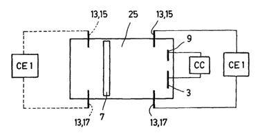
Figure 1 shows a first basic functioning mode of a relay according
3o to the invention. The relay defines an intermediate space 25 in which is
housed a conductive element 7, which can move freely along the
intermediate space 25, since physically it is a detached part which is not
physically joined to the walls which define the intermediate space 25. The
CA 02506710 2005-07-08
-l9-
relay also defines a first zone, on the left in figure 1, and a second zone,
on
the right in figure 1. In the second zone are arranged a first condenser
plate 3 and a second condenser plate 9. In the example shown in figure 1
both condenser plates 3 and 9 have different surface areas, although they
can be equal with respect to one another. The first condenser plate 3 and
the second condenser plate 9 are connected to a CC control circuit.
Applying a voltage between the first condenser plate 3 and the second
condenser plate 9, the conductive element is always attracted towards the
right in figure 1, towards the condenser plates 3 and 9. The conductive
1o element 7 will be moved towards the right until being stopped by first
stops
13, which are a first contact point 15 and a second contact point 17 of a
first external electric circuit CE1, such that the first external electric
circuit
CE1 is closed.
Figure 2 shows a second basic functioning mode for a relay
according to the invention. The relay again defines an intermediate space
in which is housed a conductive element 7, which can move freely along
the intermediate space 25, a first zone, on the left in figure 2, and a second
zone, on the right in figure 2. In the second zone is arranged a second
condenser plate 9 whilst in the first zone is arranged a first condenser plate
20 3. The first condenser plate 3 and the second condenser plate 9 are
connected to a CC control circuit. Applying a voltage between the first
condenser plate 3 and the second condenser plate 9, the conductive
element is always attracted to the right of the figure 2, towards the smallest
condenser plate, i.e. towards the second condenser plate 9. For this
25 reason, the fact that in the example shown in figure 2 both condenser
plates 3 and 9 have different surface areas is, in this case, absolutely
necessary, since if they were to have equal surface areas, the conductive
element 7 would not move in any direction. The conductive element 7 will
move towards the right until being stopped by first stops 13, which are a
3o first contact point 15 and a second contact point 17 of a first external
electric circuit CE1, such that the first external electric circuit CE1 is
closed.
On the left there are second stops 19 which in this case do not serve any
electric function but which stop the conductive element 7 from entering into
CA 02506710 2005-07-08
-20-
contact with the first condenser plate 3. In this case the stops 19 can be
removed, since no problem is posed by the conductive element 7 entering
into contact with the first condenser plate 3. This is because there is only
one condenser plate on this side, if there had been more than one and if
they had been connected to different voltages then the stops would have
been necessary to avoid a short-circuit.
The configurations of the relays of figures 1 and 2 are suitable for
being used as sensors, in which the magnitude to be measured exercises a
force which is that which will be counteracted by the electrostatic force
to induced in the conductive element 7. Such as represented, in both cases
the magnitude to be measured must exercise a force tending to open the
electric circuit CE1, whilst the electrostatic force will tend to close it.
However, a relay can be designed to work exactly in the opposite respect:
such that the magnitude to be measured would tend to close the electric
1s circuit CE1 whilst the electrostatic force would tend to open it. In this
case,
the first stops 13 would need to be positioned on the left in figures 1 and 2,
together with the corresponding electric circuit CE1. In figure 1 this
possibility has been shown in a broken line. If the stops are placed on both
sides then the sensor can detect magnitude in both directions, although the
2o algorithm would have to change, from tending to close to tending to open,
when a change in direction is detected as having occurred, as would
happen when not obtaining closing/opening with the minimum voltage,
which is zero. It should be recalled that the sign of the voltage applied
does not effect the direction of movement of the conductive element 7.
25 To achieve moving the conductive element 7 in both directions by
means of electrostatic forces, it is necessary to provide a third condenser
plate 11, as shown in figure 3. Given that the conductive element 7 will
always move towards where the smallest condenser plate is located, it is
necessary, in this case, that the third condenser plate 11 be smaller than
3o the first condenser plate.3, but that the sum of the surface areas of the
second condenser plate 9 and the third condenser plate 11 be larger than
the first condenser plate 3. In this manner, activating the first condenser
plate 3 and the second condenser plate 9, connecting them to different
CA 02506710 2005-07-08
-21-
voltages, but not the third condenser plate 11, which will remain in a state
of high impedance, the conductive element 7 can be moved to the right,
whilst activating the three condenser plates 3, 9 and 11 the conductor
element 7 can be moved to the left. In the latter case the second
condenser plate 9 and the third condenser plate 11 are supplied at a same
voltage, and the first condenser plate 3 at a different voltage. The relay of
figure 3 has, in addition, a second external electric circuit CE2 connected to
the second stops 19, in a manner that these second stops 19 define a third
contact point 21 and a fourth contact point 23.
Should two condenser plates be provided in each of the first and
second zones, the movement of the conductive element 7 can be solicited
in two different ways:
- applying a voltage between the two condenser plates of a same
zone, so that the conductive element is attracted by them (functioning as in
figure 1 )
- applying a voltage between one condenser plate of one zone and
a (or both) condenser plates) of the other zone, such that the conductive
element 7 is attracted towards the zone in which the electrically charged
condenser surface area is smallest (functioning as in figure 2).
2o Figures 4 and 5 illustrate a relay designed to be manufactured with
EFAB technology. This micromechanism manufacturing technology by
means of layer depositing is known by persons skilled in the art, and allows
the production of several layers and presents a great deal of versatility in
the design of three-dimensional structures. The relay is mounted on a
substrate 1 which serves as support, and which in several of the appended
drawings has not been illustrated in the interest of simplicity. The relay has
a first condenser plate 3 and a fourth condenser plate 5 arranged on the
left (according to figure 5) of a conductive element 7, and a second
condenser plate 9 and a third condenser plate 11 arranged on the right of
3o the conductive element 7. The relay also has two first stops 13 which are
the first contact point 15 and the second contact point 17, and two second
stops 19 which are the third contact point 21 and the fourth contact point
CA 02506710 2005-07-08
-22-
23. The relay is covered in its upper part, although this cover has not been
shown in order to be able to clearly note the interior details.
The relay goes from left to right, and vice versa, according to figure
5, along the intermediate space 25. As can be observed the first stops 13
and the second stops 19 are closer to the conductive element 7 than the
condenser plates 3, 5, 9 and 11. In this manner the conductive element 7
can move from left to right, closing the corresponding electric circuits,
without interfering with the condenser plates 3, 5, 9 and 11, and their
corresponding control circuits.
to The conductive element 7 has a hollow internal space 27.
There is play between the conductive element 7 and the walls which
form the intermediate space 25 (which is to say the first stops 13, the
second stops 19, the condenser plates 3, 5, 9 and 11 and the two lateral
walls 29) which is sufficiently small to prevent the conductive element 7
t 5 from spinning along an axis perpendicular to the plane of the drawing of
figure 5 enough to contact the first contact point 15 with the third contact
point 21 or the second contact point 17 with the fourth contact point 23. In
the figures, however, the play is not drawn to scale, so as to allow greater
clarity in the figures.
2o Figures 6 to 8 show another relay designed to be manufactured
with EFAB technology. In this case the conductive element 7 moves
vertically, in accordance with figures 6 to 8. The use of one or the other
movement alternative in the relay depends on design criteria. The
manufacturing technology consists in the deposit of several layers. In all
25 figures the vertical dimensions are exaggerated, which is to say that the
physical devices are much flatter than as shown in the figures. Should one
Wish to obtain larger condenser surfaces it would be preferable to construct
the relay with a form similar to that shown in the figures 6 to 8 (vertical
relay), whilst a relay with a form similar to that shown in figures 4 and 5
30 (horizontal relay) would be more appropriate should a lesser number of
layers be desired. Should certain specific technologies be used (such as
those usually known as polyMUMPS, Dalsa, SUMMIT, Tropic's, Qinetiq's,
etc) the number of layers will always be limited. The advantage of a
CA 02506710 2005-07-08
-23-
vertical relay is that larger surfaces are obtained with a smaller chip area,
and this implies much lower activation voltages (using the same chip area).
Conceptually the relay of figures 6 to 8 is very similar to the relay of
figures 4 and 5, and has the first condenser plate 3 and the fourth
s condenser plate 5 arranged in the lower part (figure 8) as well as the
second stops 19 which are the third contact point 21 and the fourth contact
point 23. As can be seen in the drawings the second stops 19 are above
the condenser plates, such that the conductive element 7 can bear on the
second stops 19 without entering into contact with the first and fourth
to condenser plates 3, 5. In the upper end (figure 6) is the second condenser
plate 9, the third condenser plate 11 and two first stops 13 which are the
first contact point 15 and the second contact point 17. In this case the play
between the conductive element 7 and the lateral walls 29 is also
sufficiently small to avoid the first contact point 15 contacting with the
third
15 contact point 21 or the second contact point 17 contacting with the fourth
contact point 23.
The relay shown in figures 9 and 10 is an example of a relay in
which the movement of the conductive element 7 is substantially a rotation
around one of its ends. This relay has a first condenser plate 3, a second
2o condenser plate 9, a third condenser plate 11 and a fourth condenser plate
5, all mounted on a substrate 1. Additionally there is a first contact point
15
and a third contact. point 21 facing each other. The distance between the
first contact point 15 and the third contact point 21 is less than the
distance
between the condenser plates. The conductive element 7 has a cylindrical
2s part 31 which is hollow, in which the hollow is likewise cylindrical. In
the
interior of the cylindrical hollow is housed a second contact point 17, having
a cylindrical section.
In this manner the conductive element 7 will establish an electrical
contact between the first contact point 15 and the second contact point 17
30 or the third contact point 21 and the second contact point 17. The
movement performed by the conductive element 7 is substantially a
rotation around the axis defined by the cylindrical part 31. The play
between the second contact point 17 and the cylindrical part 31 is
CA 02506710 2005-07-08
-24-
exaggerated in the figure 9, however it is certain that a certain amount of
play exists, the movement performed by the conductive element 7 thus not
being a pure rotation but really a combination of rotation and travel.
From the cylindrical part 31 extends a flat part 33 which has a
s lesser height than the cylindrical part 31, measured in the direction of the
axis of said cylindrical part 31. This can be observed in greater detail in
figure 10, in which is shown a view almost in profile of the cylindrical part
31 and the flat part 33. In this manner one avoids the flat part 33 entering
into contact with the substrate 1, which reduces the frictional forces and
to sticking.
As can be seen, substituting a parallelepipedic part for the
cylindrical part 31 and replacing the second contact point 17 having a
circular section by one having a quadrangular section, as long as play is
sufficient, one can design a relay which is conceptually equivalent to that of
is figures 9 and 10.
If, for example, in the relay shown in figures 9 and 10 the first
contact point 15 and/or the third contact point 21 were eliminated, then it
would be the very condenser plates (specifically the third condenser plate
11 and the fourth condenser plate 5) which would serve as contact points
2o and stops. By means of a suitable choice of voltages at which the
condenser plates must work one can obtain that this voltage be always
VCC or GND. Another possibility would be, for example, that the third
contact point 21 were not electrically connected to any external circuit.
Then the third contact point would only be a stop, and when the conductive
2s element 7 contacts the second contact point 17 with the third contact point
21, the second contact point 17 would be in a state of high impedance in
the circuit.
The relay shown in figure 11, is designed to be manufactured with
polyMUMPS technology. As already mentioned, this technology is known
3o by a person skilled in the art, and is characterised by being a surface
micromachining with three structural layers and two sacrificial layers.
However, conceptually it is similar to the relay shown in figures 9 and 10,
although there are some differences. Thus in the relay of figure 11 the first
CA 02506710 2005-07-08
-25-
condenser plate 3 is equal to the third condenser plate 11, but is different
from the second condenser plate 9 and the fourth condenser plate 5, which
are equal to each other and smaller than the former. With respect to the
second contact point 17 it has a widening at its upper end which permits
retaining the conductive element 7 in the intermediate space 25. The
second contact point 17 of figures 9 and 10 also can be provided with this
kind of widening. It is also worth noting that in this relay the distance
between the first contact point 15 and the third contact point 21 is equal to
the distance between the condenser plates. Given that the movement of
1o the conductive element 7 is a rotational movement around the second
contact point 17, the opposite end of the conductive element describes an
arc such that it contacts with first or third contact point 15, 21 before the
flat
part 33 can touch the condenser plates.
Figure 12 shows another relay designed to be manufactured with
polyMUMPS technology. This relay is similar to the relay of figures 4 and
5, although it has, additionally, a fifth condenser plate 35 and a sixth
condenser plate 37.
Figure 13 illustrates a relay equivalent to that shown in figures 4
and 5, but which has six condenser plates in the first zone and six
2o condenser plates in the second zone. Additionally, one should note the
upper cover which avoids exit of the conductive element 7.
Figures 14 and 15 illustrate a relay in which the conductive element
7 is cylindrical. Referring to the relay of figure 14, the lateral walls 29
which
surround the conductive element are parallelepipedic, whilst in the relay of
figure 15 the lateral walls 29 which surround the conductive element 7 are
cylindrical. With respect to figure 16, it shows a sphere manufactured by
means of surface micromachining, it being noted that it is formed by a
plurality of cylindrical discs of varying diameters. A relay with a spherical
conductive element 7 such as that of figure 16 can be, for example, very
3o similar conceptually to that of figures 14 or 15 replacing the cylindrical
conductive element 7 by a spherical one. Should be taken into account
however certain geometric adjustments in the arrangement of the
condenser plates and the contact points in the upper end, to avoid the
CA 02506710 2005-07-08
-26-
spherical conductive element 7 first touching the condenser plates and not
the contact points or, as the case may be, the corresponding stops.
Figure 17 shows a variant of the relay illustrated in figures 4 and 5.
In this case the conductive element 7 has protuberances 39 in its lateral
faces 41.
Figure 18 illustrates a variant of the relay according to the invention,
specifically designed for use as a detector of Coriolis forces (gyrostat). In
this case one can note that the relay has a first condenser plate 3 and a
fourth condenser plate 5 arranged on the left (in accordance with figure 18)
of a conductive element 7, and a second condenser plate 9 and a third
condenser plate 11 arranged on the right of the conductive element 7. The
relay also has two first stops 13, which are the first contact point 15 and
the
second contact point 17, in the upper part of figure 18, and two second
stops 19 which are the third contact point 21 and the fourth contact point
~ 5 23, in the lower part of figure 18. The conductive element 7 moves in a
zigzag fashion between the condenser plates thanks to voltages applied
between such. If the relay is subjected to Coriolis forces the conductive
element 7 will be moved laterally, i.e. upwards or downwards according to
figure 18 (supposing that the rotational movement is perpendicular to the
2o plane of drawing). In making contact with the first contact point 15 and
the
second contact point 17 (or the third contact point 21 and the fourth contact
point 23, and depending on the speed with which the zigzag is performed
(and on the geometric parameters and the masses of the relay) the Coriolis
force can be determined and, in consequence, the speed of rotation. The
25 relay also has third stops 43 and fourth stops 45 which can (additionally
and optionally) also be electric contacts. Thus the end travel of each
zigzag movement is detected by the closing of the corresponding electric
circuit, which is used by the relay control circuit. Alternatively, the
position
of the conductive element 7 can be determined by other procedures known
3o by a person skilled in the art.