Note: Descriptions are shown in the official language in which they were submitted.
CA 02506739 2005-05-19
WO 2004/053632 PCT/US2003/035765
Title: ELECTRONIC SHOPPING SYSTEM
TECHNICAL FIELD
The present invention generally relates to an electronic shopping system. In
particular, the present invention relates to systems and methods for a
shopping cart
tablet and mobile terminal.
BACKGROUND OF THE INVENTION
Retail establishments are trying to become more efficient by applying
different
and innovative operating methods that help to increase their business's
financial
condition. One of the constantly pursued goals is the reduction of a
customer's
waiting time in a checkout line. Being able to speed up the flow of customers
through
a checkout station, or to reduce cost of a checkout transaction, is important
to the
success of a retail business. An evolution of the store checkout process has
caused
replacement of manual price keying of each item being purchased, for the
process of
scanning the item. Today, the bar code readers are commonly used in commercial
and retail environments.
In a retail checkout transaction the consumer has to present all the items
he/she wants to purchase to the cashier at a checkout register. The cashier
scans each
item. In addition, there may be an identification check if the customer is
purchasing a
restricted item, such as, but not limited to, alcohol or tobacco. The
transaction is
completed once all the items have been scanned, all the coupons have been
accepted,
the total costs have been calculated, and the customer has paid for the items.
Although scanning the items at a checkout register takes less time than
manually
entering each item description into the computer, the sequential presentation
to a
cashier of each individual purchase can take a long time and create long lines
of
customers waiting to pay for their purchases. This can cause bottlenecks at
the
checkout stations, reduce throughput, make customers unhappy, and affect the
financial condition of a retail establishment. Self service checkout, or "self-
checkout", is a new way of conducting a checkout transaction and is a rapidly
growing application in the retail environment. In a self checkout system, each
customer, rather than the cashier, scans the bar codes on the items being
purchased.
Presently there exist two types of self- checkout systems.
CA 02506739 2005-05-19
WO 2004/053632 PCT/US2003/035765
In the first type of self checkout system, scanning takes place at a checkout
station.
After selecting the shopping items, a customer brings all the items to a
checkout station. A
checkout station comprises a scanner for reading product bar codes and
coupons, a weighing
scale for verifying purchased item price, and a checkout terminal for
generating the final bill
and accepting payment. At the checkout station, the customer scans the bar
codes on the
selected products, instead of having a cashier scan the items. After the
purchases have been
scanned and verified, the customer also scans any coupons-he/she might have.
The customer
requests the final bill by selecting an appropriate button on the checkout
terminal. In
response to the customer's request, the total purchase price is displayed on
the terminal
screen and the bill is printed out. The customer tenders payment to the
checkout terminal.
The terminal can accept payments by any standard payment methods. Once the
bill has been
paid and the receipt has been issued, the self-checkout transaction is
finished and the
customer can leave the store.
I5 However, although the self checkout system described above reduces labor
costs by
not having the cashier scan each item at the checkout register, it does not
reduce customer's
checkout time. In fact, the system usually increases the time to checkout,
because the
consumers are not as experienced at scanning the products as the cashiers.
Also, because
product scanning does not take place until the customer completes his shopping
item
selection, the system does not provide the customer with the real-time item
price information
or the real-time total purchase price information. This lack of cost
information during item
selection affects consumer's shopping efficiency. Consumers may either
underspend and not
purchase all the needed items, or overspend and have to return some of the
purchased
products.
The second type of self checkout system consists of a rack with portable
scanning
terminals. Price information for each item in the store is downloaded from the
store's
computer into the terminal's memory during a time when the system usage is low
or the
system is non-operational. Each customer receives one scanning terminal upon
placing their
ID or shopper loyalty card into a card reader (e.g., magnetic stripe reader.or
bar code reader)
in the rack at a log-in station. While shopping, the customer uses the
terminal to scan bar
codes associated with his purchases. The terminal generally has two scan
trigger keys: the
2
CA 02506739 2005-05-19
WO 2004/053632 PCT/US2003/035765
plus trigger key and the minus trigger key. Each trigger activates the
scanning module
located inside the terminal. When the consumer wishes to add a product to the
group of
items he wants to purchase, he uses the add trigger key to scan the product
bar code. This
process adds the item to the consumer's purchased item list inside the
terminal's memory. In
case the customer decides to return one of the items previously added to the
purchased item
list, he scans the item bar code using the minus trigger key. This process
deletes the product
from the customer's purchase item list inside the terminal's memory. In each
case the
information regarding the scanned item is displayed on the terminal screen.
This information
may include the price of the returned item as well as the quantity of the item
on the
I 0 customer's buy list. The terminal also has a total key, which is used to
display customer's
total transaction costs based upon the prices stored in the terminal's memory.
When the item
selection has been completed, the customer places the scanning terminal back
into the rack.
The customer's shopping information, which has been stored in the scanning
terminal's
memory, is downloaded through the terminal rack to the store computer, where
the
customer's transaction file is created. A ticket having a bar code printed
thereon, wherein the
bar code is encoded with the address of the customer's transaction file inside
the store
computer, gets issued to the customer. The customer takes the ticket and
proceeds to a
checkout register. When the cashier scans the bar coded ticket, the
transaction file is
retrieved from the store computer. The store computer also determines the
security
verification measures that the customer will have to undergo at a checkout
station. Those
measures are determined based upon random probability function conditioned by
the
customer's scanning accuracy during the past self-checkout transactions and
the content of
the present transaction. In certain cases all of the customer's purchases may
have to be re-
scanned. After completion of the required security checks and acceptance of
any coupons
the customer might have, the final bill is calculated. The customer settles
the bill by any
standard payment method and leaves the store.
However, the price information displayed after scanning each item may not be
synchronized to the point of sale system database, because the product price
might have
changed from the time when it was downloaded into the terminal to the time
when the
product bar code was scanned.
3
CA 02506739 2005-05-19
WO 2004/053632 PCT/US2003/035765
SUMMARY
The following presents a simplified summary of the invention in order to
provide a
basic understanding of some aspects of the invention. This summary is not an
extensive
overview of the invention. It is intended to neither identify key or critical
elements of the
invention nor delineate the scope of the invention. Its sole purpose is to
present some
concepts of the invention in a simplified form as a prelude to the more
detailed description
that is presented later.
The present invention provides systems and methods for an electronic shopping
system. The electronic shopping system includes a shopping cart tablet and a
mobile
terminal that can be hand-held and/or coupled to a shopping cart or any other
suitable
product carrying device, such as a hand-held shopping basket. The tablet
and/or mobile
terminal can include a speaker and a graphic interface which manufacturers can
use to
advertise their products as well as provide information about its products to
a customer.
Retailers may use the tablet and/or mobile terminal to provide the customer
with recipes,
store advertisements, nutritional information, etc. Icons can be displayed by
the graphical
interface to promote the various products. The tablet and/or mobile terminal
can also be
employed to provide an easy link for the customer to the manufacturer's web
site and/or the
retailer's website for product information.
Thus, in accordance with an aspect of the present invention, a shopping cart
tablet for
use in a retail environment is provided. The shopping cart tablet is adapted
for coupling to a
product carrying device, such as a shopping cart. The tablet includes a
display to display
data or other information relating to ordinary operation of the tablet and/or
a mobile terminal.
For example, software operating on the tablet and/or mobile terminal may
provide for the
display of pricing information, inventory detail, etc. to a user.
Additionally, the display may
display a variety of functions that are executable by the tablet and/or mobile
terminal. The
shopping cart tablet includes a charge cradle for charging the mobile
terminal. A plurality of
charging intelligence schemes can be employed to charge the mobile terminal.
In accordance with another aspect of the present invention, a mobile terminal
is
provided. The mobile terminal includes a window in which a bar code reader is
able.to read a
bar code label, or the like, presented to the mobile terminal. The mobile
terminal can include
a LED that is illuminated to reflect whether the bar code has been properly or
improperly
4
CA 02506739 2005-05-19
WO 2004/053632 PCT/US2003/035765
read. The mobile terminal also includes a display, which can display
information associated
with the scanning bar code. Similar to the shopping cart tablet, the mobile
terminal display
functions to display data or other information relating to ordinary operation
of the mobile
terminal and/or tablet. The mobile terminal can operate in both a presentation
mode of
operation and a hand held mode of operation.
In accordance with yet another aspect of the present invention, a shopping
cart handle
is provided. The shopping cart handle includes a gripping portion and a center
portion. The
gripping portion is designed such that a when a customer grips the handle, the
customer's
wrist is angled in a neutral position, which facilitates comfort of the
customer while
shopping. The center portion comprises an angled portion, or "tongue", which
supports a
shopping cart tablet at an angle comfortable for the customer to view. The
shopping cart
handle also includes a plurality of areas in which at least one label (e.g.,
instructional,
warning, and/or promotional labels) can be placed. The labels) can be applied
to a handle
substrate prior to injection of a clear overmold material for durability.
In accordance with yet another aspect of the present invention, a storage rack
is
provided. The rack can be a modular, mufti-configurable rack that is operable
to store andlor
charge shopping cart tablets and/or mobile terminals. The rack includes a
plurality of
cradles. The cradles are is modular and are adapted to house at least one
shopping cart tablet
and/or mobile terminal. The cradles include at least one electrical connection
for connecting
to at least one of the shopping cart tablet and the mobile terminal. The
electrical connection
can be employed to charge the shopping cart tablet and/or mobile terminal. The
cradles can
also include at least one electrical connection for connecting to at least one
other cradle.
The cradles can be mounted side to side, top to bottom, and/or back to back,
if desired.
To the accomplishment of the foregoing and related ends, the invention then,
comprises the features hereinafter fully described and particularly pointed
out in the claims.
The following description and the annexed drawings set forth in detail certain
illustrative
aspects of the invention. These aspects are indicative, however, of but a
few'of the various
ways in which the principles of the invention may be employed and the present
invention is
intended to include all such aspects and their equivalents. Other objects,
advantages and
novel features of the invention will become apparent from the following
detailed description
of the invention when considered in conjunction with the drawings.
5
CA 02506739 2005-05-19
WO 2004/053632 PCT/US2003/035765
BRIEF DESCRIPTION OF THE DRAWINGS
Figure 1 illustrates a schematic block diagram of an electronic shopping
system in
accordance with an aspect of the presentinvention.
Figure 2 illustrates a perspective front view of a shopping cart tablet and
mobile
terminal in accordance with an aspect of the present invention.
Figure 3 illustrates a perspective back view of a shopping cart tablet and
mobile
terminal in accordance with an aspect of the present invention.
Figure 4 illustrates a perspective front view of a mobile terminal in
accordance with
an aspect of the present invention.
Figure 5 illustrates a side view of a mobile terminal in accordance with an
aspect of
the presentinvention.
Figure 6 illustrates a perspective back view of a mobile terminal in
accordance with
an aspect of the present invention.
Figure 7 illustrates a schematic block diagram of an operation of a shopping
cart
tablet and/or mobile terminal in accordance with an aspect of the present
invention.
Figure 8 illustrates a block diagram of an electronic shopping system in
accordance
with an aspect of the present invention.
Figure 9 illustrates a perspective front view of a shopping cart handle in
accordance
with an aspect of the present invention.
Figure 10 illustrates a side view of a shopping cart handle in accordance with
an
aspect of the present invention.
Figure 11 illustrates a side view of a shopping cart handle in accordance with
an
aspect of the present invention.
Figure 12 illustrates a mounting mechanism for a shopping cart handle in
accordance
with an aspect of the present invention.
Figure l 3 illustrates a cup holder adapted for a shopping cart in accordance
with an
aspect of the present invention.
Figure 14 illustrates a combination of a shopping cart, shopping cart handle,
tablet,
and mobile terminal in accordance with an aspect of the present invention.
Figure 15 illustrates a combination of a shopping cart, shopping cart handle,
tablet,
and mobile terminal in accordance with an aspect of the present invention.
6
CA 02506739 2005-05-19
WO 2004/053632 PCT/US2003/035765
Figure 16 illustrates a combination of a shopping cart, shopping cart handle,
tablet,
and mobile terminal in accordance with an aspect of the present invention.
Figure 17 illustrates a storage/charging cradle for a shopping cart tablet
and/or mobile
terminal in accordance with an aspect of the present invention.
Figure 18 illustrates a plurality of storage/charging cradles coupled together
in
accordance with an aspect of the present invention.
Figure l9 illustrates a storage/charge rack located in a retail environment in
accordance with an aspect of the presentinvention.
Figure 20 illustrates a security system for an electronic shopping system in
l0 accordance with an aspect of the present invention.
Figure 21 illustrates a methodology of fabricating a shopping cart tablet in
accordance
with an aspect of the present invention.
Figure 22 illustrates a methodology of fabricating a mobile terminal in
accordance
with an aspect of the present invention.
7 5 Figure 23 illustrates a methodology of fabricating a shopping cart handle
in
accordance with an aspect of the presentinvention.
Figure 24 illustrates a methodology of fabricating a storage/charge cradle in
accordance with an aspect of the present invention.
Figure 25 illustrates a methodology for automatically associating a shopping
cart
20 tablet with a mobile terminal in accordance with an aspect of the present
invention.
Figure 26 illustrates a methodology of providing mismatch notification in
accordance
with an aspect of the present invention.
Figure 27 illustrates a methodology for mitigating theft of a shopping cart
tablet
and/or mobile terminal in accordance with an aspect of the present invention.
DETAILED DESCRIPTION OF THE INVENTION
The present invention relates to systems and methods for a shopping cart
tablet. The
present invention will now be described with reference to the drawings,
wherein like
reference numerals are used to refer to like elements throughout. It is to be
appreciated that
the various drawings are not drawn to scale from one figure to another nor
inside a given
figure, and in particular that the size of the components are arbitrarilydrawn
for facilitating
7
CA 02506739 2005-05-19
WO 2004/053632 PCT/US2003/035765
the reading of the drawings. In the following description, for purposes of
explanation,
numerous specific details are set forth in order to provide a thorough
understanding of the
present invention. It may be evident, however, that the present invention may
be practiced
without these specific details. In other instances, well-known structures and
devices are
shown in block form in order to facilitate describing the present invention.
As used in this application, the terms "component" and "system" are intended
to refer
to a computer-related entity, either hardware, a combination of hardware and
software,
software, or software in execution. For example, a component may be, but is
not limited to
being, a process running on a processor, a processor, an object, an
executable, a thread of
execution, a program, and/or a computer. By way of illustration, both an
application running
on a server and the server can be a component. One or more components may
reside within a
process and/or thread of execution and a component may be localized on one
computer
and/or distributed between two or more computers.
As used herein, the term "inference" refers generally to the process of
reasoning
about or inferring states of the system, environment, and/or user from a set
of observations as
captured vicc events and/or data. Inference can be employed to identify a
specific context or
action, or can generate a probability distribution over states, for example.
The inference can
be probabilistic - that is, the computation of a probability distribution over
states of interest
based on a consideration of data and events. Inference can also refer to
techniques employed
for composing higher-level events from a set of events and/or data. Such
inference results in
the construction of new events or actions from a set of observed events and/or
stored event
data, whether or not the events are correlated in close temporal proximity,
and whether the
events and data come from one or several event and data sources. For example,
it is to be
appreciated that certain aspects of the invention can employ inference engines
(e.g.,
classifiers trained explicitly and/or implicitly) to perform a probabilistic-
based or statistical-
based analysis as to inferring a user's goals or intentions in connection with
the shopping
system described herein. Thus, a shopping tablet can infer an item potentially
desired by a
customer based on historical, extrinsic and state information, and perform an
action related to
the item (e.g., to facilitate sale thereof). Explicit training can be
performed on a classifier
prior to customer use, and implicit training can be an on-going training
process performed by
a user/customer, for example.
8
CA 02506739 2005-05-19
WO 2004/053632 PCT/US2003/035765
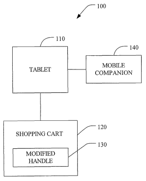
Referring initially to Figure 1, an electronic shopping system 100 is provided
in
accordance with an aspect of the present invention. The electronic shopping
system 100
comprises a tablet 110 that can be hand-held and/or coupled to a shopping cart
120 or any
other suitable product carrying device, such as a hand-held shopping basket.
For example,
the shopping cart 120 can include a handle 130 adapted to support the tablet
110, such that
the tablet 110 can rest on a handle portion of the shopping cart 120. The
tablet 110 is
adapted to house a mobile terminal 140. The tablet l 10 and/or mobile terminal
140 can
include a speaker and a graphic interface which manufacturers can use to
advertise their
products as well as provide information about its products to a customer.
Retailers may use
the tablet 110 and/or mobile terminal 140 to provide the customer with
recipes, store
advertisements, nutritional information, etc. Icons can be displayed by the
graphical
interface to promote the various products. The tablet 110 and/or mobile
terminal 140 can
also be employed to provide an easy link for the customer to the
manufacturer's web site
and/or the retailer's website for product information. The mobile terminal 140
can include a
I S barcode scanner to scan a barcode of a merchandise item.
Figure 2 illustrates an example of a shopping cart tablet 200 and a mobile
terminal
300. The shopping cart tablet 200 includes a housing 2l 0, which can be
constructed from a
high strength plastic, metal, or any other suitable material. The housing 210
is adapted for
coupling to a product carrying device, such as a shopping cart, as will be
described in further
detail below. The housing 210 includes a "lunch-box" style handle 220 for easy
removal
from a docking station, a shopping cart, or for carrying the tablet 200, for
example. The
tablei 200 also includes a display 240. As is conventional, the display 240
functions to
display data or other information relating to ordinary operation of the tablet
200 and/or
mobile terminal 300. For example, software operating on the tablet 200 and/or
mobile
terminal 300 may provide for the display of pricing information, inventory
detail, etc. to a
user. Additionally, the display 240 may display a variety of functions that
are executable by
the tablet 200 and/or mobile terminal 300. The display 240 provides for
graphics based
alpha-numerical information such as, for example, the price of a product. The
display 240
also provides for the display of graphics such as icons representative of
particular products,
for example. The display 240 can also be a touch screen, which may employ
capacitive,
resistive touch, infrared, surface acoustic wave, or grounded acoustic wave
technology.
9
CA 02506739 2005-05-19
WO 2004/053632 PCT/US2003/035765
Additional features not shown on tablet 200 can include user interface keys,
which
may include a full alphanumeric keypad, function keys, enter keys, etc; a
speaker to transmit
and/or receive audio information to and from a user; a printer system for
discharging printed
paper through a slot in the housing 210; an antenna for wireless communicating
information
with an RF access point; and an IR transceiver for communicating information
with an IR
access point. It is to be appreciated that the tablet can include a variety of
features
customized to a user's needs.
The mobile terminal 300 includes a window 310 (Figure 3) in which a bar code
reader is able to read a bar code label, or the like, presented to the mobile
terminal 300. The
mobile terminal 300 can include a LED 320 that is illuminated to reflect
whether the bar code
has been properly or improperly read. Alternatively, or additionally, a sound
may be emitted
from a speaker (not shown) to alert the user that the bar code has been
successfully imaged
and decoded. The mobile terminal 300 also includes a display 330, which can
display
information associated with the scanning bar code. Similar to the shopping
cart tablet, the
IS mobile terminal display 330 functions to display data or other information
relating to
ordinary operation of the mobile terminal 300 and/or tablet 200. For example,
software
operating on the mobile terminal 300 and/or tablet 200 may provide for the
display of pricing
information, inventory detail, etc. to a user. Additionally, the display 330
may display a
variety of functions that are executable by the mobile terminal 300 andlor
tablet 200. The
display 330 provides for graphics based alpha-numerical 'information such as,
for example,
the price of a product. The display 330 also provides for the display of
graphics such as
icons representative of particular products, for example. The display 330 can
also be a touch
screen, which may employ capacitive, resistive touch, infrared, surface
acoustic wave, or
grounded acoustic wave technology.
The mobile terminal also includes at least one user input key for accepting or
rejecting at least on scanned image, such as a bar code. If the scanned image
is accepted, the
information can be transmitted from the mobile terminal 300 to the tablet 200.
For example,
the mobile terminal 300 can have two user input keys: a plus key 340 and a
minus key 345.
When a bar code of an item is scanned, product information can be displayed on
the. display
330 of the mobile terminal. If the user wishes to add the item to a shopping
list, for example,
the user can select the plus key 340 and the item information is transmitted
to the tablet.
CA 02506739 2005-05-19
WO 2004/053632 PCT/US2003/035765
However, if the user does not wish to transmit the item information to the
tablet, the user can
select the minus key 345 and the information will be cleared from the mobile
terminal 300.
Alternatively, each of the user input keys 340, 345 can activate a scanning
module
located inside the mobile terminal 300. When the customer wishes to add a
product to the
group of items he wants to purchase, he uses the plus key 340 to scan the
product bar code.
This can automatically transmit the item information to the tablet 200. Then,
if the customer
decides to return one of the items previously added to the purchased item,
list, the item bar
code is rescanned using the minus key 345. This process deletes the product
from the
customer's purchase item list inside the tablet's memory. In each case the
information
regarding the scanned item is displayed on the mobile terminal display 330
and/or the tablet
display 240. This information may include the price of the item as well as the
quantity of the
item on the customer's shopping list.
The shopping cart tablet 200 and/or mobile terminal 300 can also include a
smart card
slot (not shown), a magnetic stripe reader (not shown), and/or a biometric
sensor, such as a
thumbprint reader (not shown). Accordingly, a smart card, ID card, and/or a
user's biometric
data (e.g., iris pattern, fingerprint, facial features) can be employed to
provide for storage and
retrieval of a customer's personal information, demographic profile, and
shopping transaction
history data. Alternatively, or additionally, personal information can be
provided via a user
ID and password, which a customer enters into the shopping cart tablet and/or
mobile
terminal. Customer identification information can be employed to determine an
award of
incentive or loyalty points and/or whether the customer is eligible for any
special discounts.
Turning now to Figure 3, a back view of the shopping cart tablet 200 and
mobile
terminal 300 is depicted. The shopping cart tablet housing 210 may be
comprised of a
number of shell portions such as for example front and rear shells (not shown)
as well as a
battery compartment cover (not shown). Accordingly, the tablet housing 210 is
adapted for
easy disassembly to accommodated repair and replacement of parts such as
batteries and/or
lights, for example. The shopping cart tablet 200 also includes at least one
electrical contact
270 for coupling to a docking station, as will be described in further detail
below.
When lithium battery cells are employed in the shopping Bart tablet 200,
charging and
discharging must be regulated. When a lithium cell is charged for too long or
when a lithium
cell is charged with too much energy, the lithium can release combustible
gasses at very high
11
CA 02506739 2005-05-19
WO 2004/053632 PCT/US2003/035765
temperatures, which can lead to fire, explosion, and injury to the user. Thus,
the shopping
cart tablet 200 can include a battery protection circuit scheme that can sense
charge and
discharge rates, as well as cell voltage and temperature. If an anomaly is
detected (e.g.,
excessively high charge or discharge current levels, high cell voltage levels,
high cell
temperature, etc.), the protection circuitry will open. The open circuit
operates to isolate the
cell from external battery terminals, which protects people and equipment. Low
drain to
source resistance transistors can be connected in series with the battery
cells as pass
elements. The transistors open under fault conditions.
The tablet housing 210 also includes a battery operated cradle 230 for docking
the
mobile terminal 300. Accordingly, the mobile terminal 300 can be charged via a
tablet
battery and/or tablet power source without being powered into an external
power source. A
plurality of charging intelligence schemes can be employed between the tablet
200 and the
mobile terminal 300. For example, the battery charge states between the tablet
200 and the
mobile terminal 300 can be correlated such that both the battery in the tablet
200 and the
I S battery in the mobile terminal 300 can have substantially the same amount
of usable life left
at any given time. As another example, the mobile terminal 300 will not be
permitted to
charge when the tablet battery charge state is below a predetermined threshold
and the
mobile terminal battery charge is above a predetermined threshold. As yet
another example
of a charging intelligence scheme, the mobile terminal 300 will not be
permitted to charge
when the mobile terminal's battery state reaches full capacity. It is to be
appreciated that any
other suitable charging intelligence scheme can be employed and is
contemplated as falling
within the scope of the present invention.
Figures 4-6 depict a mobile terminal 400 in accordance with an aspect of the
present
invention. The mobile terminal 400 includes a housing 405, which can be
fabricated from a
high strength plastic, metal, or any other suitable material. The mobile
terminal housing 405
can include a number of shell portions such as for example front and rear
shells 410 and 415.
The mobile terminal housing 405 includes a manually graspable handle portion
430 and a
head portion 435 (Figure 5). The shape of the mobile terminal housing 405
facilitates an
ergonomically suitable handheld terminal, as well as~ a proper scanning
position of the
terminal 400 when mounted in a shopping cart tablet. At least one button,
preferably two
buttons 440 and 445 are included in the mobile terminal 400, which can be
easily accessed
12
CA 02506739 2005-05-19
WO 2004/053632 PCT/US2003/035765
by a thumb of a user while gripping the handle portion 430 of the mobile
terminal 400. The
buttons 440 and 445 can include a scan button for activating a scanning unit
inside the
mobile terminal 400. An indicator light 450 such as a multicolor LED, can also
be included '
to indicate an operational mode of the mobile terminal 400. For example, if a
barcode has
been successfully read, the indicator light 450 can illuminate green, if a
barcode is not
successfully read or the mobile terminal 400 does not recognize the barcode,
the indicator
light 450 can illuminate red.
As an alternative, or in addition to the at least one button 440 and 445, the
mobile
terminal 400 can include a touch pad (not shown) which is of the type that
may, for example,
control scrolling of information on a display 455, and also provide selection
of functions or
features. Alternatively, manual key activation could also be provided by a
touch screen
display having software defined user interface buttons which could be
configured to provide
user input commands. Alternatively, a thumbwheel (not shown) could be provided
to scroll
through various options and select a desired command or field. The thumbwheel
would have
I 5 a rotating function for scrolling in one of two directions and be capable
of pressing to select a
specific selection once it is selected.
The mobile terminal can employ a two-dimensional imaging assembly. The imaging
assembly includes a two-dimensional photosensor and an optic assembly
supported in a lens
housing or shroud for focusing an image of a dataform, for example, in a field
of view onto
the photosensor array. Conventionally available circuitry on printed circuit
boards operate to
sequentially read out charges accumulating on photosensors of the photosensor
array,
generate an analog composite video signal, store a digital representation of a
captured image,
and decode the captured image to generate the decoded data signal. At least a
portion of this
image capture, image processing, and decoding circuitry may be implemented in
code
executed by a processor on the printed circuit board. The illumination
assembly of the
mobile terminal can include four sets of illumination light emitting diodes
(LEDs) (not
shown), which can be positioned on a printed circuit board. The illumination
LEDs direct
illumination through corresponding aligned lens portions of a lens array
towards the imaging
field of view. Two targeting LEDs operate to_direct illumination through
aligned apertures in
board and through aligned lens portion in the lens array and generate the
cross hair
illumination pattern in the field of view to assist the operator in relatively
positioning the
13
CA 02506739 2005-05-19
WO 2004/053632 PCT/US2003/035765
mobile terminal and the dataform. As noted above, the cross hair illumination
pattern is
generated when the mobile terminal is used in the hand held mode.
The mobile terminal housing 405 can also support a speaker (not shown) which
can
be driven by audio indicator driver circuitry mounted on the control printed
circuit board.
The speaker can be employed to provide audio feedback suitably in the form of
a 1 /2 second
beep, for example, to the customer to indicate a successful bar code dataform
read and
decode.
Figure 6 depicts a back view of the mobile terminal 400 in accordance with an
aspect
of the present invention. Batteries (not shown) for the mobile terminal 400
can be located
within the body of the terminal 400, rather than being located within a
conventional battery
compartment. Accordingly, the weight and size of the mobile terminal 400 is
distributed
over the body of the terminal 400, thereby facilitating ease of gripping
and/or holding of the
mobile terminal 400. However, it is to be appreciated that the mobile terminal
400 can
alternatively, or additionally, include any number of battery compartments,
including one,
and is contemplated as falling within the scope of the present invention.
The mobile terminal 400 can also include a battery protection circuit scheme
that can
sense charge and discharge rates, as well as cell voltage and temperature. If
any anomaly is
detected (e.g., excessively high charge or discharge current levels, high cell
voltage levels,
high cell temperature, etc.), the protection circuitry will open. The open
circuit operates to
isolate the cell from external battery terminals, which protects people and
equipment. Low
drain to source resistance transistors can be connected in series with the
battery cells as pass
elements. The transistors open under fault conditions.
Turning now to Figure 7, a schematic representation according to one aspect of
the
present invention is shown in which a processor 705 is responsible for
controlling the general
operation of a shopping cart tablet and/or mobile terminal 700. The processor
705 is
programmed to control and operate the various components within the shopping
cart tablet
andlor mobile terminal 700 in order to carry out the various functions
described herein. The
processor or CPU 705 can be any of a plurality of suitable processors. The
manner in which
the processor 705 can be programmed to carry out the functions relating to the
present
invention will be readily apparent to those having ordinary skill in the art
based on the
description provided herein.
14
CA 02506739 2005-05-19
WO 2004/053632 PCT/US2003/035765
A memory 710 tied to the processor 705 is also included in the shopping cart
tablet
and/or hand-held mobile terminal 700 and serves to store program code executed
by the
processor 705 for carrying out operating functions of the shopping cart tablet
and/or hand-
held mobile terminal 700 as described herein. The memory 710 also serves as a
storage
medium for temporarily storing information such as receipt transaction
information and the
like. The memory 710 is adapted to store a complete set of the information to
be displayed.
According to one aspect, the memory 710 has sufficient capacity to store
multiple sets of
information, and the processor 705 could include a program for alternating or
cycling
between various sets of display information.
A display 715 is coupled to the processor 705 via a display driver system 720.
The
display 715 may be a liquid crystal display (LCD) or the like. In this
example, the display
715 is a'/a VGA display with 16 levels of gray scale. The display 715
functions to display
data or other information relating to ordinary operation of the shopping cart
tablet and/or
hand-held mobile terminal 700. For example, the display 715 may display a set
of customer
information, which is displayed to the operator and may be transmitted over a
system
backbone (not shown). Additionally, the display 715 may display a variety of
functions that
control the execution of the shopping cart tablet and/or mobile terminal 700.
The display 715
is capable of displaying both alphanumeric and graphical characters. Power is
provided to
the processor 705 and other components forming the shopping cart tablet and/or
hand-held
mobile terminal 700 by at least one battery 725. In the event that the
battery(s) 725 fails or
becomes disconnected from the shopping cart tablet and/or mobile terminal 700,
a
supplemental power source 730 can be employed to provide power to the
processor 705. The
shopping cart tablet and/or mobile terminal 700 may enter a minimum current
draw of sleep
mode upon detection of a battery failure.
The shopping cart tablet and/or mobile terminal 700 includes a communication
subsystem 735 that includes a data communication port 740, which is employed
to interface
the processor 705 with the main computer. The shopping cart tablet and/or
mobile terminal
700 also optionally includes an RF section 745 connected to the processor 705.
The RF
section-745 includes an RF receiver 750, which receives RF transmissions from
the main
computer for example via an antenna 755 and demodulates the signal to obtain
digital
information modulated therein. The RF section 745 also includes an RF
transmitter 760 for
CA 02506739 2005-05-19
WO 2004/053632 PCT/US2003/035765
transmitting information to the main computer, for example, in response to an
operator input
at a operator input device 765 (e.g., keypad) or the completion of a
transaction. Peripheral
devices, such as a printer 770, signature pad 775, and magnetic stripe reader
780, and an
additional barcode scanner/imager 785 can also be coupled to the shopping cart
tablet and/or
mobile terminal 700 through the processor 705.
Turning now to Figure 8, a schematic block diagram of an electronic shopping
system
800 is provided. The electronic shopping system 800 includes retail
environment 805, which
includes a shopping cart tablet 810, through a shopping cart tablet 810N and a
mobile
terminal 820 through a mobile terminal 820M, N and M being integers greater
than or equal
to one. The shopping cart tablets 810, through 81 ON will be collectively
referred to as 810;
and the mobile terminals 820 through 820M will be collectively referred to as
820. The
shopping cart tablets) 810 and the mobile terminals) 820 include an
identification
component 830 and 835, respectively, which provide the shopping cart tablets)
810 and the
mobile terminals) 820 with unique IDs. At least one of the shopping cart
tablets) 810
and/or the mobile terminals) 820 can also include an auto association
component 840 and/or
845 that associates at least one tablets) 810 with at least one mobile
terminals) 820.
Accordingly, when a mobile terminals) 820 is coupled to a shopping cart
tablets) 810, the
mobile terminals) 820 and/or the shopping cart tablets) 810 serially sends its
unique ID
information to the shopping cart tablets) 810 and/or the mobile terminal(s),
respectively.
The ID information is employed by the shopping cart tablets) 810 and/or the
mobile
terminals) 820 to automatically associate itself with the mobile terminals)
820 and/or the
shopping cart tablets) 810. The association can be exclusive or the shopping
cart tablets)
810 and/or the mobile terminals) 820 can have a plurality of associations. The
auto
association component 840, 845 facilitates dynamic reconfiguration of the
shopping cart
tablets) 810 with the mobile terminals) 820, and/or vice versa; and thus,
mitigates the need
for manually setting an association between the shopping cart tablets) 810 and
the mobile
terminals) 820.
At least one notification component 850, 855 can also be included in at least
one of
the shopping cart tablets) 810 and/or mobile terminal(s).820. The notification
component
850, 855 can be employed to notify at least one of the shopping cart tablets)
810 andlor the
mobile terminals) 820 of incorrect docking of the mobile terminals) 820 within
a charge
16
CA 02506739 2005-05-19
WO 2004/053632 PCT/US2003/035765
cradle of the shopping cart tablets) 810. When a mobile terminals) 820 is
docked within
the charge cradle, at least one of the shopping cart tablets) 810 and the
mobile terminals)
820 sends its )D information to the other device. The shopping cart tablets)
810 and/or the
mobile terminals) 820 can determine whether the tablets) 810 is properly
associated with an
assigned mobile terminals) 820. The notification component 850, 855 can alert
a user of
any mismatch via a message, sound, light, or any other suitable alert
mechanism.
Additionally, the notification component 850, 855 can alert a system
administrator of any
mismatch via an email notification, for example.
Figure 9 depicts a shopping cart handle 900 in accordance with an aspect of
the
present invention. The shopping cart handle 900 includes a gripping portion
905 and a center
portion 910. The gripping portion 905 is designed such that a when a customer
grips the
handle 900, the customer's wrist is angled in a neutral position, which
facilitates comfort of
the customer while shopping. The center portion 910 comprises an angled
portion, or
"tongue", 915 which supports a shopping cart tablet at an angle comfortable
for the customer
to view. The shopping cart handle 900 also includes a plurality of areas in
which at least one
label (e.g., instructional, warning, and/or promotional labels) can be placed.
For example,
the shopping cart handle 900 can include a first label area 920 for a tablet
insertion
instructional label; and a second label area 925 for a branding label (e.g., a
retail store name,
a product name). If a cup holder, as described in further detail below, is
coupled to the
shopping cart, a third label area 930 can be included for a hot beverage
warning label. The
labels can be applied to a handle substrate prior to injection of a clear
overmold material for
durability. Employing a substantially transparent overmold material, such as
polycarbonate,
for example, mitigates user wear on any logos and/or legends that can be
applied to the
shopping cart handle 900.
The tongue portion 915 of the shopping cart handle includes a passive locking
mechanism 935, which can secure the shopping cart tablet to the handle 900 and
still allow
for easy removal of the shopping cart tablet from the handle 900. The passive
locking
mechanism 935 includes a recess on a center area of the tongue portion 915.
However, it is
to be appreciated that the .passive locking mechanism can be employed in any
suitable area
for coupling the shopping cart tablet to the handle 900. Turning back to
Figure 3, the
shopping cart tablet 200 includes a projection 280 in a central back portion
of the shopping
17
CA 02506739 2005-05-19
WO 2004/053632 PCT/US2003/035765
cart tablet housing 270. The projection 280 corresponds with the recess in the
shopping cart
handle 900. Accordingly, the mating projection and recess features mitigate
the tablet from
easily decoupling from the handle 900. For example, the locking mechanism 935
mitigates
the tablet from being pulled out easily by a child in a child seat.
Additionally, the locking
mechanism 935 mitigates the tablet from falling out of the handle 900 in a
head-on cart
collision. It is to be appreciated that any suitable locking mechanism (e.g.,
passive,
aggressive, permanent, non-permanent) can be employed for coupling the
shopping cart
tablet to the handle 900.
The shopping cart handle 900 is also designed to facilitate nesting of a
plurality of
shopping carts during storage. For example, the center portion 915 of the
shopping cart
handle 900 is raised high enough to mitigate interference of the handle 900
and a nested cart
(see Figure 1 l ). The shopping cart handle 900 is also designed such that it
allows for the use
of a child seat of the cart and/or for the use of a baby bassinette on the
shopping cart.
Further, the tongue portion 915 of the shopping cart handle 900 is designed to
close the child
I 5 seat of an approaching cart. For example, see Figure 10. In Figure 7 0 a
first cart 1000 is
being nested into a second cart 1010; the first cart 1000 has its child seat
1020 open. The
tongue portion 1030 of a shopping cart handle 1040 on the second cart 7010 is
adapted to
close the open child seat 1020 during the nesting process (Figure 11).
The shopping cart handle 900 also includes an attachment mechanism 940 for
attaching the handle 900 to a shopping cart 945, as depicted in Figure l2. The
attachment
mechanism 940 includes at least one endcap 950 and optionally, at least one
endcap cover
955. The shopping cart handle 900 includes at least one flange portion 960,
preferably two
flange portions located at opposing ends of the handle 900. The flanges) 960
is adapted to
fit adjacent to, partially cover, or cover a portion of the shopping cart
frame 945. The
endcap(s) 950 is adapted to mate with the flanges) 960. Both the endcap(s) 950
and the
flanges) 960 include at least one bore 965, 970 for coupling the mating parts
950, 960. The
bores 965, 970 can be threaded or non-threaded and a conventional screw and/or
nut and bolt
assembly can be employed to couple the endcap(s) 950 and the flanges) 960 and
secure the
shopping cart handle 900 to the shopping cart 945. The endcap(s) 950 can also
include an
anti-torque wedge 975 for mitigating torque on the attachment mechanism 940.
The endcap
covers) 955 can be snapped onto an exposed portion of the endcap(s) 950 to
hide the
18
CA 02506739 2005-05-19
WO 2004/053632 PCT/US2003/035765
screws) and/or bolts) utilized to secure the shopping cart handle 900 to the
shopping cart
945.
Although employing the shopping cart tablet and mobile terminal have been
described herein as being employed with the shopping cart handle; it is to be
appreciated that
the shopping cart tablet and mobile terminal can be coupled to a conventional
shopping cart
without the shopping cart handle described herein.
Figure 13 illustrates a cup holder 1300 for a shopping cart 1310 in accordance
with an
aspect of the present invention. The cup holder 1300 can be fabricated from a
wire and
includes a receptacle portion 1320, which is adapted to hold a plurality of
different sizes of
l0 cups. The cup holder 1300 can also be plastic, rubber, or any other
suitable material for
supporting hot and/or cold beverages while the customer is shopping. The cup
holder 1300
can also include a mounting portion 1330 for securing the cup holder 1300 to a
frame portion
of the shopping cart 1310. The mounting portion 1330 includes spring features,
which can
be integrated into at least a portion of the cup holder 1300. Depending on the
strength of the
spring features, the cup holder 1300 can be easily removed from the shopping
cart 1310 or
can be substantially fixed in place. Alternatively, a mounting portion having
a plate and
fasteners to "sandwich" a cup holder wireframe to a shopping cart wireframe
can be
employed. However, it is to be appreciated that any suitable mounting
mechanism can be
employed to secure the cup holder to the shopping cart frame.
Figure 14 depicts an electronic shopping system 7400 in accordance with an
aspect of
the present invention. The electronic shopping system 1400 includes a shopping
cart 1405
having a shopping cart handle 1410 coupled thereto. The shopping cart handle
1410 is
adapted to support a shopping cart tablet 1415 andlor a mobile terminal 1420.
A cup holder
(not shown) can also be coupled to the shopping cart 1405 for user
convenience.
The mobile terminal 1420 is adapted to operate in at least two modes: a) a
hand held
mode; and b) a presentation mode. The hand held mode of operation is
represented in Figure
14, wherein the mobile terminal 1420 is removed by the customer from a charge
cradle of the
shopping cart tablet 1415. When supported in the charge cradle, the mobile
terminal 1420
extends slightly beyond the tablet housing so that the customer can easily
grasp a front
portion of the mobile terminal 1420 and slide it out of the charge cradle. The
customer
moves the mobile terminal 7420 to a dataform 1425 of an item 1430 so desired
to be
19
CA 02506739 2005-05-19
WO 2004/053632 PCT/US2003/035765
purchased or priced by the customer. The customer activates a suitable
selector, such as
depressing a button 1435 on the mobile terminal 1420 to actuate an imaging
assembly (not
shown) and an illumination assembly (not shown) of the mobile terminal 1420.
The
illumination assembly advantageously provides a substantially uniform
illumination pattern
that substantially corresponds to an imaging area or field of view of the
imaging assembly
and additionally generates a more intense cross hair illumination pattern to
aid the customer
in positioning the mobile terminal 1420 so that the dataform 1425 of an item
1430 is properly
within the imaging area of the mobile terminal 1420.
The substantially uniform illumination pattern and cross hair aiming pattern
are
rapidly alternated between off and on states, such that one is off while the
other is on. This
alternation of illumination patterns avoids the difficulty of having to decode
a captured
dataform image which has intense cross hair illumination patterns imposed
thereon. The
alternation of the illumination and cross hair patterns is rapid enough that
it appears to the
customer that the cross hair aiming pattern is continuously on.
~ While keeping the button 1420 depressed, the customer aims the cross hair
pattern at
the dataform 1425. The customer moves the mobile terminal 1420 toward the item
1430
until an audible tone or "beep" is emitted by a speaker of the mobile terminal
and/or
shopping cart tablet 1415 indicating the dataform 1425 has been successfully
read and
decoded. The item's price, product name or description and product size will
appear on a
display 1440 of the mobile terminal 1420 and/or a display 1445 of the shopping
cart tablet
1415. After the beep is heard, the mobile terminal 1420 is returned to the
charge cradle and
slid into the housing of the shopping cart tablet 1415.
In the presentation mode of operation shown in Figure 15, the mobile terminal
1420
is disposed in the charge cradle and the customer reads a dataform 1425
affixed to an item
1430 by moving the item 1430 to the mobile terminal 1420. While the mobile
terminal 1420
remains in the charge cradle, a magnetic switch enclosed in a back portion of
the mobile
terminal housing is turned on by a magnet positioned in the shopping cart
tablet housing.
Actuation of the magnetic switch causes the imaging assembly and the
illumination assembly
to remain actuated. Thus, the mobile terminal 1420 is continuously able to
read a dataform
when it is disposed in the charge cradle. When a "beep" is heard, the customer
knows that
the dataform has been successfully imaged and decoded. In this presentation
mode, the
CA 02506739 2005-05-19
WO 2004/053632 PCT/US2003/035765
illumination pattern is continuously on and the cross hair illumination
pattern is deactivated
since properly aiming the mobile terminal 1420 is not a concern. A customer
will typically
pass an item by the mobile terminal 1420 to read a code much like a cashier
passes an item
over a common countertop scanner. The hand held mode is advantageously used
when an
item on a shelf is too large or too clumsy to move from the shelf or if the
customer just
wishes to check a price without removing the item from the shelf. The
presentation mode is
advantageously employed when a selected item is smaller and more easily
handled.
The shopping cart tablet and mobile terminal assembly is also easily removable
from
the shopping cart handle, as illustrated in Figure 16. Accordingly, a user can
employ the
electronic shopping system when shopping without a shopping cart.
Shopping cart tablets and mobile terminals, as described herein, can be housed
in a
storage and/or charge rack located in the retail environment. The rack can be
a modular,
mufti-configurable rack that is operable to store and/or charge shopping cart
tablets and/or
mobile terminals. The rack includes a plurality of cradles. Turning now to
Figure 17, an
IS example of a cradle 1700 is illustrated. A housing 1710 of the cradle 1700
can be fabricated
from a high strength plastic, metal, or any other suitable material. The
cradle 1700 is
modular and is adapted to house at least one shopping cart tablet (not shown)
and/or mobile
terminal (not shown). The cradle 1700 includes at least one electrical
connection for
connecting to at least one of the shopping cart tablet and the mobile
terminal. The electrical
connection can be employed to charge the shopping cart tablet and/or mobile
terminal. The
cradle 1700 can also include at least one electrical connection for connecting
to at least one
other cradle.
Turning now to Figure 18, a plurality of docking stations 1800 can be coupled
together for storing and/or charging a plurality of shopping cart tablets (not
shown) and/or
mobile terminals (not shown). The docking stations I 800 include a plurality
of cradles 1810
and cradle housings 1820. The cradle housings I 820 can include at least one
connector
element for coupling the housings 1820 together. Alternatively, connections in
the cradles
1810 can be employed to couple the docking stations 1800 together. The docking
stations
1800 can be mounted in any configuration suitable for physical layout of a
storage andlor
charging rack in a retail environment. For example, the docking stations 1800
can be
mounted side to side, top to bottom, andlor back to back, if desired.
21
CA 02506739 2005-05-19
WO 2004/053632 PCT/US2003/035765
Figure 19 illustrates an example of a storage and/or charging rack I 900 for a
plurality
of shopping cart tablets and/or mobile terminals. Electrical connections (not
shown) can be
included on the rack 1900 to transmit information between the shopping cart
tablet and/or the
mobile terminal and the rack 1900. For example, the rack 1900 can include a
smart charge
system. The system can recognize in which rack 1900 and/or cradle a particular
shopping
cart tablet and/or mobile terminal is residing. Identification information can
be passed from
the rack slot to the tablet and/or mobile terminal electronically upon
insertion of the tablet
and/or mobile terminal. Additionally, or alternatively, identification
information from the
shopping cart tablet and/or mobile terminal can be passed to the rack 1900
and/or cradle
upon insertion of the tablet and/or mobile terminal.
Alternatively, the rack can include one unit with a plurality of electrical
connections
for storing and/or charging a plurality of tablets and/or mobile terminals;
and/or the rack can
include a plurality of units wherein each unit has a plurality of electrical
connections for
communication and/or for charging a plurality of tablets andlor mobile
terminals. It is to be
I S appreciated that although the rack and cradles have been described herein
as being adapted to
charge the shopping cart tablet and/or mobile terminal. The rack and cradles
may simply be
a storage place for the shopping cart tablet and/or mobile terminal and does
not necessarily
require charge functionality.
Figure 20 depicts a security system 2000 in accordance with an aspect of the
present
invention. A shopping cart tablet 2010 and/or a mobile terminal 2020 located
within a retail
environment 2030 can be coupled to the security system 2000 to prevent theft
of the
shopping cart tablet 2010 and the mobile terminal 2020. For example, a
wireless system can
be installed at or within a close proximity to at least one exit 2040 in the
retail environment
2030. As the shopping cart tablet 2010 and/or the mobile terminal 2020 enter
or come within
close proximity of the wireless system, the wireless ID of the shopping cart
tablet 2010
and/or mobile terminal 2020 is interrogated via at least one communication
channel 2050.
The shopping cart tablet 2010 and/or mobile terminal 2020 can communicate via
a
transceiver or communication can occur directly with at least one access point
of the retail
environment 2030. Upon detection of the wireless ID(s), the wireless ID(s) is
compared to a
database or list of known "in-store" devices. If the detected ID(s) matches an
"in-store"
device, an alarm 2060 will sound to provide notification that at least one
shopping cart tablet
22
CA 02506739 2005-05-19
WO 2004/053632 PCT/US2003/035765
2010 andlor mobile terminal 2020 is about to leave the retail environment
2030. If, on the
other hand, the detected ID(s) does not match an "in-store" device listed in
the database, the
alarm 2060 will not be activated.
The security system 2000 can employ a BIueTooth communication protocol. The
shopping cart tablet 2010 and/or the mobile terminal 2020 can include
BIueTooth radios.
The BlueTooth ID of the shopping cart tablet 2010 and/or the mobile terminal
2020 can be
interrogated at or near at least one exit 2040 of the retail environment 2030.
Bluetooth is a
Radio Frequency (RF) specification for short-range, point to multi-point voice
and data
transfers. Bluetooth can transmit through solid, non-metal objects. It has a
nominal link
range from 10 centimeters to 10 meters, but can be extended to 100 meters by
increasing the
transmit power. It is based on short-range radio links and facilitates ad hoc
connections for
stationary and mobile communication environments. The Bluetooth standard is a
low cost,
short-range wireless communication standard that typically operates in the
2,400-2,483.5
MHz industrial, scientific and medical (ISM) band. The ISM band is available
worldwide
and allows unlicensed operation of spread spectrum systems. The Bluetooth
standard is often
employed for short distance connections and can be employed to replace cables
used today
that, for example, connect laptops to cellular telephones, printers, desktops,
fax machines,
joysticks and many other digital devices that can be part of the Bluetooth
system. Bluetooth
can also provide a bridge to existing data networks. Bluetooth is specifically
designed to
provide low-cost, robust, efficient, high capacity, ad Izoc voice and data
networking.
Bluetooth technology has been designed to operate in noisy radio frequency
environments and uses a fast acknowledgment and frequency hopping scheme to
make a
robust communications link. Bluetooth radio modules attempt to avoid
interference from
other signals by hopping to a new frequency after transmitting or receiving a
packet as
compared to other systems operating at the same frequency band. The
implementations of
faster hops and shorter packets limit impact of microwave and other sources of
interference.
Bluetooth uses forward error correction to limit impact of random noise on
longer distance
links.
The Bluetooth specification employs frequency hopping spread spectrum
techniques.
The Bluetooth specification further provides a standard method data
transmission between
Bluetooth devices employing, for example, RFComm, OBEX, Service Discovery
Protocol
23
CA 02506739 2005-05-19
WO 2004/053632 PCT/US2003/035765
andlor logical link control and adaptation protocol. Another example of a
frequency hopping
spread spectrum wireless communications protocol is ConnexRF by AeroComm. It
is to be
appreciated that alternative frequency adjusting wireless communication
protocols (e.g., to
achieve improved noise immunity) are also encompassed within the present
invention (e.g.,
direct sequence spread spectrum).
It is to be appreciated that any suitable communication protocol can be
employed.
For example, the network can employ Ethernet (IEEE 802.3), Wireless Ethernet
(IEEE
802.1 1 ), PPP (point-to-point protocol), point-to-multipoint short-range RF
(Radio
Frequency), WAP (Wireless Application Protocol), IP, IPv6, TCP and User
Datagram
Protocol (UDP). Further, the network connection can be via an extranet and/or
a shared
private network. For example, the network connection can be via a phone
connection (not
shown) from the shopping cart tablet 2010 and/or mobile terminal 2020 to an
Internet Service
Provider (ISP) to the security system 2000. Another possible 'network
connection is via a
Local Area Network (LAN) to the security system 2000. It is noted that the
shopping cart
tablet 2010 and/or mobile terminal 2020 can communicate over a separate and
isolated
network from the security system network. Information exchanged between and
among the
shopping cart tablet 2010 and/or mobile terminal 2020 and the security system
2000 can be
in a variety of formats and can include, but is not limited to, such
technologies as HTML,
SHTML, VB Script, JAVA, CGI Script, JAVA Script, dynamic HTML, PPP, RPC,
TELNET, TCP/IP, FTP, ASP, XML, PDF, EDI, WML as well as other formats.
At least one of the shopping cart tablet and mobile terminal can also include
a system,
such as a global positioning system (GPS), for determining a location of the
shopping cart
tablet and/or mobile terminal and for transmitting information to and from the
shopping cart
tablet and/or mobile terminal.
While, for purposes of simplicity of explanation, the methodologies of Figures
21-27
are shown and described herein as executing serially, it is to be understood
and appreciated
that the present invention is not limited by the illustrated order, as some
aspects could, in
accordance with the present invention, occur in different orders and/or
concurrently with
other aspects from that shown and described herein. Moreover, not all
illustrated features
may be required to implement a methodology in accordance with an aspect the
present
invention.
24
CA 02506739 2005-05-19
WO 2004/053632 PCT/US2003/035765
Turning now to Figure 21, a methodology for fabricating a shopping cart tablet
is
depicted. The methodology begins at 2110 where a housing for the shopping cart
tablet is
provided. The housing can be fabricated from a metal, high strength plastic,
and/or any other
suitable material. At 2120, the housing is provided with a charge cradle to
support a portable
electronic terminal, such as a barcode reader. At 2130, the housing is
provided with a
display for displaying product information scanned by the portable electronic
terminal. The
housing is also provided with at least one electrical connection at 2140 to
connect to a
docking station or other charging device. At 2150, a battery protection
circuit is provided in
the housing. The battery protection circuit is operable to mitigate damage
from excess
l0 charging, voltage, and/or temperature.
Figure 22 illustrates a methodology for fabricating a mobile terminal in
accordance
with an aspect of the present invention. The methodology begins at 2210 where
a housing
for the mobile terminal is provided. The housing can be fabricated from a
metal, high
strength plastic, and/or any other suitable material. At 2220, the body of the
housing is
adapted to receive at least one to distribute the size and weight of the
battery(s) over the
mobile terminal housing, rather then employing a conventional battery
compartment. At
2230, an image scanning system is provided within the housing of the mobile
terminal. The
image scanning system is operable to scan and decode a bar code of a product,
for example.
The mobile terminal is further adapted to couple to a shopping cart tablet, at
2240. For
example, the mobile terminal can include at least one electrical connection
for electrically
connecting to a charge cradle of the shopping cart tablet. Additionally, the
mobile terminal
can be equipped for wireless communication with the shopping cart tablet. At
2250, a
display is provided to display product information of a scanned product and/or
an operational
status of the mobile terminal.
Figure 23 illustrates a methodology for fabricating a shopping cart handle in
accordance with an aspect of the present invention. The methodology begins at
2310 where a
housing is provided. The housing includes a gripping portion which is angled
such that a
user's wrist is positioned in a neutral position when gripping the shopping
cart handle. At
2320, a passive locking mechanism is provided on the shopping cart handle for
coupling of
the handle with a shopping cart tablet and/or mobile terminal. The passive
locking
mechanism comprises a recess which corresponds with an aperture located in the
shopping
CA 02506739 2005-05-19
WO 2004/053632 PCT/US2003/035765
cart tablet and/or mobile terminal. A substantially transparent material is
provided on the
shopping cart tablet at 2330 for allowing the application of logos and/or
legends on the
shopping cart handle. The shopping cart handle further includes a mounting
mechanism for
coupling the shopping cart handle to at least one frame portion of a shopping
cart. The
mounting mechanism includes at least one flange portion and at least one
mating endcap
portion.
Figure 24 depicts a methodology for fabricating a modular charge cradle in
accordance with an aspect of the present invention. The methodology begins at
2410 where a
housing adapted to house a shopping cart tablet and/or a mobile terminal is
provided. At
least one attachment mechanism is coupled to the housing to facilitate
physical connection of
a plurality of cradles at 2420. At least one electrical connection is coupled
to the housing of
the charge cradle at 2430. At least one electrical connection is adapted to
facilitate charging
of the shopping cart tablet and/or mobile terminal that is docked in the
cradle. Another
electrical connected can be adapted to facilitate communications between a
storage/charging
rack and the shopping cart tablet and/or mobile terminal. Accordingly
identification
information can be passed electronically from the cradle to the shopping cart
tablet and/or
mobile terminal.
Turning now to Figure 25, a methodology for providing an auto association
between a
tablet and a mobile terminal is illustrated. The methodology begins at 2510
where the mobile
terminal is coupled with a shopping cart tablet. The mobile terminal can be
inserted into a
cradle located in the tablet. At 2520, the mobile terminal detects power from
the tablet.
Then, at 2530, the mobile terminal serially sends an ID associated with the
mobile terminal
to the tablet. The mobile terminal's ID information is employed by the tablet
to
automatically associate itself with the mobile terminal. The association can
be exclusive to
that particular mobile terminal. The auto association facilitates dynamic
reconfiguration of
the tablet with other mobile terminals; and mitigates the need for manually
setting an
association between the tablet and the mobile terminal(s).
Turning now to Figure 26, a methodology for incorrect docking notification is
depicted. The methodology begins at 2610 where a mobile terminal is coupled
with a
shopping cart tablet. The mobile terminal can be inserted into a cradle
located in the tablet.
At 2620, the mobile terminal detects power from the tablet. Then, at 2630, the
mobile
26
CA 02506739 2005-05-19
WO 2004/053632 PCT/US2003/035765
terminal serially sends an ID associated with the mobile terminal to the
tablet. The tablet can
determine whether the tablet is properly associated with an assigned mobile
terminal. At
2640, the tablet determines if the serial ID stored in the tablet, which was
obtained during an
initial association, matches the serial ID sent by the mobile terminal. If the
stored tablet ID
does not match the received ID from the mobile terminal (NO), the user is
alerted of the
mismatch at 2650. If the stored tablet ID does match the received mobile
terminal ID (YES),
no notification is provided to the user (2660).
Figure 27 illustrates a methodology for preventing theft of electronic
shopping system
components in accordance with an aspect of the present invention. The
methodology begins
at 2710 where a security zone is installed around at least one exit located in
a retail
environment. Accordingly, when a device (e.g., shopping cart tablet, mobile
terminal) enters
the security zone at 2720, identification information about the device is
transmitted to the
security system. The identification information is compared to a database or
listed of known
IDs. At 2730, it is determined whether the identification information
transmitted to the
security system matches a stored ID. If there is a match, the alarm is
activated at 2740 to
notify personnel at the retail environment that a store device is about to
leave the retail
environment. However, if no match is found, no alarm is sent (2750), as there
may be a
plurality of electronic devices not owned by the store that pass through the
security zone.
What has been described above includes exemplary implementations of the
present
invention. It is, of course, not possible to describe every conceivable
combination of
components or methodologies for purposes of describing the present invention,
but one of
ordinary skill in the art will recognize that many further combinations and
permutations of
the present invention are possible. Accordingly, the present invention is
intended to embrace
all such alterations, modifications and variations that fall within the spirit
and scope of the
appended claims.
27