Note: Descriptions are shown in the official language in which they were submitted.
CA 02506926 2005-05-09
PLASTICS MOLDINt3 FOR OSTOMY DEVICE
Field of the Invention
The present invention may relate to the field of plastics
molding, for example, for an ostomy device. Particular
aspects of the invention may relate to a molding method,
molding apparatus, and to a molded product usable in an
ostomy device. The invention may be especially applicable
to blow molding a component of an ostomy device.
Background to the Invention
In the technically specialized field of ostomy devices,
IS fusion is a commonly used technique for bonding together two
plastics components. Examples of fusion techniques include
solvent bonding, heat welding and ultrasonic welding. These
techniques generally involve at least partly melting and
fusing the two components together after the components have
been formed as separate parts. However, such processes
necessitate additional manufacturing equipment and
processing steps, and add to the cost and complexity of
manufacture. There is also a risk of failure of, or leakage
from, the weld, resulting from occasional welding errors or
anomalies. The manufacturing complexity and risk of failure
may be exacerbated when one or both of the components is a
blow molded component. A blow molded component typically
has a thin wall that may be at least partly deformable, and
this can make welding complicated shapes difficult. Should a
failure or leak occur during use by an ostomate, not only is
this highly embarrassing and unhygienic for the ostomate, it
may also lead to customer rejection of the product in this
highly personal field.
1
CA 02506926 2005-05-09
Summary of tha Invention
Broadly speaking, in one aspect of the invention, a method
S of forming an ostomy device component may include blow
molding a (second) portion of the component into intimate
contact with a preformed (first) portion.
The intimate contact achieved during the blow molding
operation can enable a strong and permanent bond to be
achieved between the two portions, without requiring any
additional welding or other fusion step after the molding
operation. The blow molding operation may thus achieve two
simultaneous effects of (i) imparting a desired shape to the
blow molded (second) portion, and (ii) integrally bonding
the two portions together.
The invention can therefore avoid the additional welding
steps of the conventional manufacturing techniques, leading
to improved quality components, and more efficient
manufacture.
As used herein, the term "blow molding" may mean any molding
process that uses a pressure differential between an
internal pressure and an external pressure, to cause a
plastics body (e. g. parison) to expand and to adopt a shape
define by a surrounding mold.
The material from which the second portion is blow molded
may be a body of material that is independent of the first
portion. The material from which the second portion is blow
molded may, prior to the blow molding operation, be
unattached to the first portion.
2
CA 02506926 2005-05-09
The first portion may be any preformed part. For example,
the first portion may be preformed by injection molding,
blow molding, vacuum forming, machining or casting. The
first portion could alternatively comprise any of a fabric,
textile or non-woven polymer material. The first portion
may be a molded part or a sheet material, for example,
plastics film. The first portion may itself be a sub-
assembly of multiple parts.
The first portion may be generally rigid (or at least more
rigid than the second portion). Alternatively, the first
portion may be substantially flexible (or at least more
flexible than the second portion).
The first and second portions may be formed of material
having substantially the same or similar melting
temperatures. Such a technique has been found to provide
good bonding between the first and second portions.
The first portion may comprise the same or a similar
plastics material to the second portion. Alternatively, the
materials used for the first and second portions may be
different. The first and second portions may achieve a
plastics bond, or a mechanical bond, or a combination of
both.
Broadly speaking, a second aspect of the invention may
relate to a mold apparatus that may be used in the above
method. The, or a, mold apparatus may include a first mold
region for accommodating and/or preforming a first preformed
portion, and a second mold region for defining a blow mold
shape of a second portion.
3
CA 02506926 2005-05-09
Broadly speaking, a third aspect of the invention may
provide an ostomy device component produced by the method of
the first aspect and/or the mold apparatus of the second
aspect.
Broadly speaking, a fourth aspect of the invention may
provide an ostomy device component that includes integrally
molded first and second portions, at least one portion (e. g.
the second portion? being a blow molded part.
The first and second portions of the component may include
any of the aforementioned features.
The first portion may, in ane form, comprise a ring-shaped
member and/or a cover member. The first portion may be
configured as a coupling member for coupling to a
counterpart coupling member. Additionally or alternatively,
the second portion may, in one form, comprise a generally
tubular portion. The tubular portion may be collapsible
and/or extendable in a direction generally parallel to the
axis of the tubular portion. The tubular portion may have
an open end and/or a closed end. The tubular portion may
have a concertina and/or bellows profile. The tubular
portion may be flexible and/or bendable. The tubular
portion may define an ostomy collection chamber.
The above aspects of the invention may be used independently
or in combination, as desired.
Other aspects, features and advantages of the invention may
be described in the appended claims and/or in the following
description and drawings. Protection is claimed for any
4
CA 02506926 2005-05-09
novel feature and/or combination of features described
herein and/or illustrated in the drawings whether or nor
emphasis has been placed thereon.
Brief Description of the Drawings
Non-limiting preferred embodiments of the invention are now
described, by way of example only, with reference to the
accompanying drawings, in which:
Fig. 1 is a perspective schematic view of a component of an
ostomy device;
Fig. 2 is a schematic cross-section through the component of
Fig. 1;
Figs. 3a-a are schematic diagrams illustrating molding of
the component of Fig. 1;
Fig. 4 is a schematic diagram illustrating a second modified
embodiment of an ostomy device component;
Fig. 5 is a schematic section illustrating a mold for
forming the component of Fig. 4;
Fig. 6 is a schematic diagram illustrating a third modified
embodiment of an ostomy device component;
Fig. 7 is a schematic section illustrating a mold for
forming the component of Fig. 6; and
Fig. 8 is a schematic section illustrating a part of a
fourth modified embodiment of an ostomy device component.
S
CA 02506926 2005-05-09
Detailed Description of Preferred Smbodiments
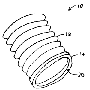
Referring to Figs. 1 and 2, a component 10 for an ostomy
device may be shown. The component 10 may define at least
partly a chamber for collecting body waste. The component
may include a first portion 14 from which extends or
depends a second portion 16. The first portion 14 may be
generally ring shaped. The first portion 14 may be an
10 injection molded part. The first portion 14 may be partly
flexibl a andjor resiliently deformable, but may generally
have a well-defined natural shape. The second portion 16 may
be generally tubular. The second portion 16 may be a blow
molded part. The second portion 16 may be more flexible
than the first portion 14, and may define a concertina
bellows capable of being collapsed or expanded in an axial
direction. Although the component 10 may be illustrated in
Fig. 1 as having a generally circular cross-section shape,
any closed-loop shape may be used. One of the first and
second portions 14 and 16 may be configured to encircle the
other in the region 15 of mutual contact.
The first portion 14 may be configured to support the shape
of the tubular second portion 16. The first portion 14 may
be configured to provide structural support for the second
portion 16. The first portion 14 may additionally or
alternatively be configured as a coupling member for
coupling to a counterpart annular coupling member (shown in
phantom at 18 in Fig. 2?. The first portion 14 may be
intended to be releasably coupled to the counterpart
coupling member 18, to enable the component 10 to be
releasably secured to the counterpart member 18. The first
portion 14 may, for example, include a coupling
6
CA 02506926 2005-05-09
configuration 20 for releasable locking engagement with the
counterpart member 18. The coupling configuration 20 may
include a channel 22 and one or more locking projections or
latches 24 that may be undercut relative to the adjacent
wall material of the coupling configuration 20.
The first and second portions 14 and 16 may be of material
(e.g. plastics) having the substantially the same, or
similar, melting temperatures. The first and second
portions 14 and 16 may be of the same, or similar, plastics
material. For example, the plastics material may be an
ethylene vinyl acetate, although a wide variety of similar
and dissimilar plastics may be used, as desired.
It may be preferred to form the first portion 14 by
injection molding. For example, the first portion 14 may
have a relatively thick wall thickness (e.g. about 1 mm, or
more) that is better suited to formation by injection
molding than blow molding. The coupling configuration 20 of
the first portion 14 may also have a level of intricacy that
may be suited to injection molding, but may be difficult to
achieve by blow molding. In contrast, it may be preferred
to form the second portion 16 by blow molding. For example,
the second portion 16 may have a relatively thin wall
thickness (e.g. about 1 mm or less, typically between 0.1
and 0.3 mm) that may be better suited to formation by blow
molding than injection molding. Also, blow molding may
enable the second portion 16 to be formed consuming far less
plastics material than injection molding, thus leading to
significant material economy.
Figs. 3a-a may illustrate a mold apparatus 30 and mold
method for forming the component of Figs. 1 and 2. In the
7
CA 02506926 2005-05-09
present embodiment, the first portion 14 may formed before
the second portion 16. The first portion 14 may be
preformed in the same mold apparatus as the second portion
16, or the first gortion 14 may be preformed in a different
mold apparatus (not shown) and transferred to the mold
apparatus 30. In the present embodiment, the first portion
14 may have a relatively complicated shape that might best
be molded in a separate mold apparatus (or, at least, a
separate mold cavity).
The mold apparatus 30 may generally comprise mold segments
or shells 32 (e. g. mold halves) that together define a mold
cavity 34. The mold shells 32 may include at least one
first mold region 36 shaped to accommodate the preformed
first portion 14, and at least one second mold region 38
shaped to define the final shape of the second portion 16.
In the present embodiment, the first mold region 36 may
comprise an annular recess or groove for receiving the pre-
formed ring-shaped first portion 14. The second mold region
38 may comprise a bellows shaped surface 38a for defining
the bellows profile of the second portion 16, and a lip
surface 38b for defining a radially directed lip 26 of the
second portion 16 at the opposite end of the second portion
l6 to the first portion 14. The second mold region 38 may
be configured to mold the second portion 16 either in a
fully extended condition, or in a partly extended condition,
or in a fully or substantially collapsed condition.
Referring to Fig. 3a, the mold shells 32 may firstly be
opened (e.g. moved apart) to allow access to the interior of
the cavity. Referring to Fig. 3b, the preformed first
portion 14 may be inserted or placed at the first mold
region 36, and the mold shells 32 closed (e. g., moved
8
CA 02506926 2005-05-09
towards each other). Referring to Fig. 3c, an extruded
parison 40 may be introduced into the mold apparatus 30 to
extend through one or more apertures 42. Referring to Figs.
3d and 3e, the parison 40 may be heated and expanded by
blowing gas (e.g. air) into the parison 40 to cause the
parison to inflate and adopt the shape defined by the second
mold region 38. At the same time, the parison 40 may be
forced into intimate contact with the preformed first
portion 14 retained in the first mold region 36, to form a
secure and permanent mold bond between the first and second
portions 14 and 16.
The above technique of blow molding a portion 16 of the
component into intimate contact with a preformed portion 14
has been found to provide excellent bonding characteristics
between the two portions 14 and 16. The blow molding
operation forces the material of the two portions into firm
contact, and -enables a strong and uniform bond to be
achieved with an excellent reliability and repeatability,
leading to consistently high manufacturing quality. The
quality and reliability may exceed that achievable
economically by the prior art technique of welding the two
portions together after both portions have been formed as
separate parts. Avoiding such a welding step may also
improve the manufacturing efficiency because it may no
longer be necessary to provide dedicated welding equipment
and welding process steps for bonding two discrete portions
together.
The blow molding technique may comprise one or more of:
extrusion blow molding, injection blow molding, vacuum
forming, pressure forming, and/or plug assist thermoforming.
9
CA 02506926 2005-05-09
In the illustrated embodiment, the adjoined faces of the
first and second portions 14 and 16 may be generally planar.
Alternatively, the adjoined faces may be keyed or embossed
in order to increase the engagement between the first and
second portions 14 and 16, which may increase the strength
of the bond.
Figs. 4-8, may illustrate modified embodiments of the
invention for the purposes of illustration. The same
reference numerals may be used where appropriate to identify
features already described.
Fig. 4 may illustrate a second form of component 110. The
component 110 may be similar to the component 10 described
above, except that first portions 14 may be provided at both
ends of the second portion 16. Each first portion 14 may be
configured as a coupling member for coupling to respective
counterpart members (not illustrated in Fig. 4).
Fig. 5 may illustrate a second form of mold apparatus 130
for forming the second component 110. The mold apparatus
130 may include two first mold regions 36 for accommodating
the two preformed first portions 14 at opposite ends of the
mold cavity 34. The mold apparatus 130 may function in the
same manner as the apparatus 30 described above.
Fig. 6 may illustrate a third form of component 210. The
component may be similar to the component 10 described above
except that one end of the second portion 16 may be closed
by a cover portion 214. The cover portion 214 may be
injection molded, similarly to the first portion 14. The
cover portion 214 may extend laterally outside the second
portion. The cover portion 214 may be configured to
CA 02506926 2005-05-09
releasably engage the counterpart coupling member 18 when
the second portion 16 is collapsed down.
Fig. 7 may illustrate a third form of mold apparatus 230 for
forming the third component 210. The mold apparatus 230 may
include two first mold regions 36 in a similar manner to the
apparatus 130 described above. The parison 40 may extend
through a single aperture 42, and be configured to be blown
into intimate contact with the cover portion 214 as well as
the first portion 14, to form a tubular chamber closed at
one end.
Fig. 8 may illustrate molding of a fourth form of component
310. The component 310 may be similar to the component 10
described above, except that the first portion 14 may be
preformed by a technique other than injection molding. Such
other techniques may comprise one or more of: blow molded,
vacuum formed, machined and/or cast. A further possibility
is that the first portion 14 may be of or comprise one or
more of: fabric, textile or non-woven polymer material. A
yet further possibility is that the first portion 14 may be
a sheet material, for example, plastics film.
Although the foregoing embodiments have been described in
the form of a component including a ring-shaped first
portion 14 and a tubular second portion 16, this is merely
for the purposes of illustration. The invention may be used
to form a wide variety of different component shapes and
configurations in the ostomy field.
The techniques of the present invention are especially
advantageous and beneficial in the field of ostomy devices.
The manufacture of such devices presents unique challenges
CA 02506926 2005-05-09
in terms of forming low-cost, lightweight devices that are
straightforward to use and comfortable to wear. At the same
time, security and hygiene are of utmost importance to the
wearer. Ostomy devices should have a high integrity against
leakage, and be robust enough to withstand body movements
and accidental knocks without accidentally releasing body
waste. The present invention permits a mufti-part component
including at least a blow molded part to be integrally
formed by a process which is efficient from the point of
view of manufacture, yet also achieves the degree of
strength and reliability demanded for the specialized field
of ostomy devices.
The foregoing description is merely illustrative of
preferred forms of the invention. Many modifications,
improvements and equivalents may be used within the scope
and/or spirit of the invention.
12