Note: Descriptions are shown in the official language in which they were submitted.
CA 02507428 2005-06-08
- 1 -
SPECIFICATION
HYDROGEN GAS SENSOR
Field of the Invention:
[0001] This invention relates to a hydrogen gas sensor which is
suitable for detecting hydrogen gas leaked in air or analyzing the
concentration of the hydrogen gas.
Background of the art:
[0002] It is desired in a future hydrogen energy utilizing society to
establish a convenient hydrogen energy system from which the
hazardous nature of hydrogen explosion is removed to develop the
safety of the hydrogen energy system. It is required that the
hydrogen gas sensor is configured such that the hydrogen gas amount
leaked in air can be detected at once and the structure of the hydrogen
gas sensor can be simplified, and the reliability of the hydrogen gas
sensor can be enhanced.
[0003] A conventional hydrogen gas sensor is configured on the
detecting principle of semiconductor type, ionization type or
combustion type, wherein the hydrogen amount is detected indirectly
by utilizing the carrier concentration (semiconductor type), the ion
concentration (ionization type) or the reaction heat (combustion type,
or the hydrogen gas is burned to measure the vapor pressure) which
can be defined as an extensive physical value, thereby to be converted
into the corresponding electric value. With the conventional hydrogen
gas sensor, therefore, it takes longer period of time to detect the
hydrogen gas, e.g., by 100 seconds. Particularly, with a hydrogen gas
sensor which is to be utilized in a hydrogen leak alarm system, it is
required that the hydrogen gas sensor is configured so as to detect the
hydrogen gas concentration within a low concentration range below the
explosion limit and shorten the period of time in hydrogen detection.
[0004] With the conventional (semiconductor type, ionization type
or combustion type) hydrogen gas sensor, since the hydrogen gas
concentration is detected by utilizing the carrier concentration, the ion
concentration or the reaction heat as a hydrogen gas detecting signal,
04907 (1/25)
CA 02507428 2005-06-08
- 2 -
the hydrogen detection requires a large detecting area. In this point
of view, the detection precision and sensitivity of the hydrogen gas
depends on the structure, the shape and the electrode size of the
hydrogen gas sensor, so that the reduction in size of the hydrogen gas
sensor is restricted. Moreover, the conventional (semiconductor type,
ionization type or combustion type) hydrogen gas sensor may suffer
from environmental gases. Particularly, when the hydrogen gas
sensor is employed in the atmosphere containing gasoline, hydrocarbon
and alcohol which contain hydrogen elements, the hydrogen gas sensor
may respond to the hydrogen-based gases, thereby to deteriorate the
reliability of the hydrogen gas detection.
[0005] In this point of view, new electrochemical gas sensors have
been developed and practically used, in substitution for the above-
mentioned conventional hydrogen gas sensors. The new gas sensors
can be classified as electromotive force measuring type hydrogen gas
sensors and current detecting type hydrogen gas sensors. With the
former type hydrogen gas sensors, as disclosed in Patent Publication
No. 1 and 2, a hydrogen gas electrode is prepared as a standard
electrode which is configured on the hydrogen standard gas pressure,
and a detecting electrode is prepared as an operating electrode for
measuring the gas to be detected (hydrogen gas), wherein the
difference in potential between the hydrogen gas electrode and the
detecting electrode is measured as the output of the hydrogen gas
sensor corresponding to the hydrogen gas concentration.
[0006] With the hydrogen electrode, the atomicity hydrogen exists
sufficiently on the electrode surface to form the standard potential of
the electrode. Under the condition, when hydrogen gas contacts with
the detecting electrode to be dissociated into atomicity hydrogen, the
detecting electrode exhibits an electric potential in proportion to the
amount of the atomicity hydrogen, and the difference in potential
between the hydrogen gas electrode and the detecting electrode is
detected as the function of the hydrogen gas concentration. In other
words, with the new hydrogen gas sensors, since the detecting hydrogen
04907 (2/25)
CA 02507428 2005-06-08
- 3 -
gas pressure is measured in comparison with the standard hydrogen gas
pressure, both of electrodes must be disposed independently in the
standard hydrogen gas atmosphere and the detecting gas atmosphere,
so that another "standard hydrogen gas pressure room must be provided
in addition of the detecting gas pressure room. In this point of view,
the hydrogen gas sensors are required to be enlarged in size and the
use condition and the like of the hydrogen gas sensors are restricted.
[0007] With the current detecting type hydrogen gas sensors, the
current value is classified as an extensive physical value, so that in
order to realize a high precise measurement using the hydrogen gas
sensors, the areas or the volumes of the hydrogen gas sensors must be
enlarged and external power supplies can be provided for the hydrogen
gas sensors.
[0008] [Patent Publication No. I]
Japanese Patent Application Laid-open No. 2003-270200
[Patent Publication No. 2]
Japanese Patent Application Examined Publication No. 5-663
Disclosure of the Invention:
Problem to be solved by the Invention:
[0009] It is an object of the present invention to provide a new
electromotive force type hydrogen gas sensor on electrochemical
principle wherein the structure of the hydrogen gas sensor is
simplified and the hydrogen gas can be detected high precisely at once.
Means for solving the Problem:
[0010] In order to achieve the object, this invention relates to a
hydrogen gas sensor comprising a first electrode, a second electrode
and an electrolyte contacting with the first electrode and the second
electrode,
wherein the first electrode and the second electrode are made of
corresponding different materials in chemical potential for hydrogen
gas, and the first electrode is made of higher chemical potential
material and the second electrode is made of lower chemical potential
material,
04907 (3/25)
CA 02507428 2011-03-25
- 4 -
wherein the hydrogen gas is detected on an electromotive force
generated between the first electrode and the second electrodes,
wherein said first electrode material includes at least one selected from
the group consisting of Pt and Pt alloy and said second electrode material
includes at least one selected from the group consisting of Ni, Ni alloy, Ti,
Ti
alloy, Cu, Cu alloy, Fe, Fe alloy, Al, Al alloy and organic conductive
material.
[0011] In the present invention, the electrodes of the hydrogen gas
sensor are configured so as to contain the corresponding different
materials in chemical potential from one another, and the first
electrode containing the higher chemical potential material is defined
as a detecting electrode and the second electrode containing the lower
chemical potential material is defined as a standard electrode.
Therefore, when the hydrogen gas sensor is disposed in the same
atmosphere containing hydrogen gas, the difference in potential
between the first electrode and the second electrode of the hydrogen
gas sensor is generated because the electrodes are made of the
different materials in chemical potential, respectively. As a result,
the hydrogen gas under the same atmosphere can be detected from the
difference in potential between the electrodes.
[0012] According to the hydrogen gas sensor of the present
invention, since another standard hydrogen gas pressure room is not
required different from the conventional electromotive force
measuring type hydrogen gas sensor, the structure of the hydrogen gas
sensor can be simplified and the size of the hydrogen gas sensor can be
reduced, and also, the hydrogen gas can be detected at once.
[00131 Herein,
the difference in potential between the electrodes of
the hydrogen gas sensor is originated from the following relative
equation
.................................................... (1)
CA 02507428 2011-03-25
,
- 4a -
wherein the reference character "F" means Faraday constant, and the
reference character "E" means EMF value, and 11, ri= re are electro-
chemical potentials are equal to chemical potentials, respectively of
atomicity hydrogen for metal and hydrogen gas. Then, since the
terminals [I] and [II] are made of the same copper wire, the electro-
chemical potentials of electron are represented by the following
equation:
'Le al lie (2)
CA 02507428 2005-06-08
- 5 -
_
Herein, the equation (3) showing the relation between the electrostatic
potential and the electromotive force E is employed:
........................................ (3)
wherein 4)1 means an electrostatic of the first electrode and 4)11 means
an electrostatic of the second electrode.
[0014] In this way, the hydrogen gas sensor of the present
invention
derives the electromotive force corresponding to the chemical potential
difference originated from the atomicity hydrogen concentration for
both of the electrodes, and detects the hydrogen gas concentration on
the electromotive force. As mentioned above, in the present
invention, the first electrode is configured as the detecting electrode
such that the first electrode contains the higher chemical potential
material and the second electrode is configured as the standard
electrode such that the second electrode contains the lower chemical
potential material, so that the electromotive force E is originated
mainly from the electrostatic potential of the first electrode.
[0015] Since the electromotive force E depends only on the
kinds of
the electrode materials relating to the chemical potential, not on the
size and structure of the electrodes, the hydrogen gas sensor can be
reduced in size and simplified in structure. Moreover, since the
above-mentioned reaction is created as soon as the hydrogen gas
contacts with the first electrode as the detecting electrode, the
hydrogen gas detection can be carried out at once.
[0016] Herein, since the hydrogen gas sensor of the present
invention has an inherent spontaneous electromotive force under non-
hydrogen atmosphere, the hydrogen gas sensor can have the self-
diagnosed function relating to the operationality.
[0017] In the hydrogen gas sensor, the chemical potential
can be
associated with the absorption-dissociation active degree of hydrogen
gas. That is, the hydrogen gas sensor can be configured such that the
electrodes can contain the corresponding different materials in
hydrogen absorption-dissociation active degree from one another.
In this case, if the first electrode is made of a material of higher
04907 (5/25)
CA 02507428 2005-06-08
- 6 -
- absorption-dissociation active degree for hydrogen gas and the
second
electrode is made of a material of lower absorption-dissociation active
degree for hydrogen gas, the first electrode can contain the higher
chemical potential material and the second electrode can contain the
lower chemical potential material.
[0018] Concretely, the first electrode can contain a first
electrode
material which can exhibit a standard electromotive force of 0.8V or
over in the cell of H2(¨)150mol/m3 H2SO4 I sample(+), and the second
electrode can contain a second electrode material of less than 0.8V in
the same cell construction.
[0019] As the first electrode material can be exemplified Pt, Pt alloy,
Pd, Pd alloy. The first electrode can be made of the above-
exemplified material or a supported material of the above-exemplified
material on a given substrate. The first electrode can be formed in
any construction within a scope of the present invention only if the
first electrode can function as the detecting electrode for hydrogen gas.
[0020] As the second electrode material can be exemplified
Ni, Ni
alloy, Ti, Ti alloy, Cu, Cu alloy, Fe, Fe alloy, Al, Al alloy and organic
conductive material. The second electrode can be made of the above-
exemplified material, but can be formed in any construction within a
scope of the present invention only if the second electrode can
function as the standard electrode for the hydrogen gas.
[0021] A hydrogen gas sensor wherein the detecting
electrode for
hydrogen gas is made of Pd-H is disclosed in Non-patent Publication
No. 1. In this case, since hydrogen gas is partially evaporated from
the detecting electrode with time in use, the hydrogen gas sensor can
not exhibit the inherent effect/function. In contrast, in the present
invention, such a hydrogen-containing electrode is not employed, the
above-mentioned problem relating to the use of the hydrogen-
containing electrode can be ironed out.
[0022]
[Non-patent Publication No. 1]
A. Macker et al., ASTM Spec Tech Publ. No. 962(1998/06),
04907 (6/25)
CA 02507428 2005-06-08
- 7 -
p90-97
[0023] Moreover, the electrolyte may be made of liquid electrolyte
or solid electrolyte, but preferably made of the solid electrolyte.
In this case, the handling of the hydrogen gas sensor can be simplified,
and can be precisely operated within a temperature range of room
temperature (0 C)-120 C. If a micro heater or the like is installed in
the hydrogen gas sensor, the hydrogen gas can be detected easily
within a low temperature range of 0 C or below.
[0024] As the solid electrolyte can be exemplified phosphorous
tungstic acid or phosphorous molybdic acid which has good adhesion
for the first electrode and the second electrode and is excellent as an
electrolyte for the hydrogen gas sensor.
[0025] The phosphorous tungstic acid and the phosphorous molybdic
can be obtained in the form of powder, so that in the fabrication of the
solid electrolyte, the powdery phosphorous tungstic acid or phosphorous
molybdic acid is pressed and molded in pellet, and then, processed into
the solid electrolyte. However, the pellet is too fragile to be
employed for the solid electrolyte as it is. In the use, therefore, some
glass wool are added as reinforcing material into the powdery
phosphorous tungstic acid or phosphorous molybdic acid in a given
solvent (such as ion exchanged water), thereby to be solidified to
provide the solid electrolyte. Concretely, the solid electrolyte will be
made by the following steps:
(1) A powdery raw material for the intended solid electrolyte (such as
phosphorous tungstic acid) is melted in a given solvent to be liquidized,
(2) A reinforcing material is set into a mold for forming the solid
electrolyte,
(3) The liquidized raw material is flowed into the mold containing the
reinforcing material,
(4) The liquidized raw material is solidified to form the solid
electrolyte as the primitive form of the hydrogen gas sensor.
[0026] Herein, it may be that the solid electrolyte is melted and the
reinforcing material is added to the melted electrolyte, in substitution
04907 (7/25)
CA 02507428 2005-06-08
- 8 -
- for the step (2).
[0027] In one aspect of the present invention, the hydrogen
gas
sensor is combined with a voltage comparator to form a hydrogen gas
leak alarm system, wherein an electromotive force created on the
hydrogen gas detection by the hydrogen gas sensor is compared with a
reference voltage of the voltage comparator, and if the electromotive
force is larger than the reference voltage, a predetermined alarm is
raised.
[0028] In another aspect of the present invention, a
plurality of
hydrogen gas sensors are prepared, and arranged on the same substrate
to form a hydrogen gas sensor array. According to the hydrogen gas
sensor array, hydrogen gas leak from a pipe line series can be detected
to form the hydrogen gas leak distribution. If the sensors are arranged
densely in series, the sensor output voltage can be enhanced by several
times.
[0029] In still another aspect of the present invention,
the hydrogen
gas sensor is combined with an electric circuit for detecting the
electromotive force from the hydrogen gas sensor, thereby to form a
hydrogen gas analyzer which detects hydrogen gas concentration on
the electromotive force.
Effect of the Invention:
[0030] As described above, since the hydrogen gas sensor of
the
present invention is configured such that the electrodes are made of
the corresponding different material in chemical potential for
hydrogen gas and the hydrogen gas is detected by the difference in
electromotive force between the electrodes corresponding to the
difference in the chemical potential therebetween, the hydrogen gas
detection can be carried out at once and the detection performance of
hydrogen gas under a low hydrogen gas concentration can be enhanced.
Moreover, since the chemical potential and the electromotive force are
defined as extensive physical values and do not depend on the size of
the electrodes, the hydrogen gas sensor of the present invention can be
downsized. Also, since the hydrogen gas sensor can be disposed with
04907 (8/25)
CA 02507428 2005-06-08
- 9 -
_
- the electrodes in the same atmosphere, another standard
hydrogen gas
pressure room is not required. Therefore, the structure of the
hydrogen gas sensor can be simplified and the size of the hydrogen gas
sensor can be reduced. In addition, the hydrogen gas sensor can have
the inherent spontaneous electromotive force under the non-hydrogen
atmosphere, the hydrogen gas sensor can have self-diagnosed function
of the operationality.
Brief Explanation of the Drawings:
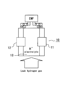
[0031] Fig. 1 is a structural view illustrating a hydrogen
gas sensor
according to the present invention,
Fig. 2 is a graph showing an electromotive force between the
electrodes 11 and 12 of the hydrogen gas sensor illustrated in Fig. 1
when the hydrogen gas sensor is disposed in a hydrogen-containing
atmosphere,
Fig. 3 is a graph showing the relation between the
electrostatic potential and the hydrogen gas concentration at the first
electrode of the hydrogen gas sensor illustrated in Fig. 1,
Fig. 4 are structural views illustrating another hydrogen gas
sensor according to the present invention, Fig. 4(a) being a top plan
view of the hydrogen gas sensor, Fig. 4(b) being a side view of the
hydrogen gas sensor,
Fig. 5 is a structural view illustrating still another hydrogen
gas sensor according to the present invention,
Fig. 6 is a structural view illustrating a further hydrogen gas
sensor according to the present invention,
Fig. 7 is a structural view illustrating a still further hydrogen
gas sensor according to the present invention,
Fig. 8 is a view illustrating the state where the hydrogen gas
sensor illustrated in Fig. 7 is integrated,
Fig. 9 is a structural view illustrating a hydrogen gas sensor
array according to the present invention,
Fig. 10 is a view illustrating the state where a plurality of
hydrogen gas sensors according to Fig. 7 are arranged and connected
04907 (9/25)
CA 02507428 2005-06-08
- 10 -
- to one another in series,
Fig. 11 is a block diagram of a hydrogen gas leak alarm
system utilizing a hydrogen gas sensor according to the present
invention,
Fig. 12 is a block diagram of a hydrogen gas leak controlling
system utilizing a hydrogen gas sensor according to the present
invention,
Fig. 13 is a block diagram of a hydrogen gas leak information
transmitting system utilizing a hydrogen gas sensor according to the
present invention,
Fig. 14 is a schematic explanatory view of the structure and
operation of the voltage comparator in the systems illustrated in
Figs. 11-13,
Fig. 15 is a block diagram of a hydrogen gas analyzer
utilizing a hydrogen gas sensor according to the present invention,
Fig. 16 is a block diagram of the hydrogen gas leak alarm
system with Fail-Safe function, and
Fig. 17 is a schematic structural view of a hydrogen gas
sensor element with Fail-Safe function.
Preferred Embodiments for Carrying Out the Invention:
[0032] Details, other features and advantages of the
present
invention will be described hereinafter, with reference to "Preferred
Embodiments for Carrying out the Invention".
[0033] Fig. 1 is a structural view illustrating a hydrogen
gas sensor
according to the present invention. Like or similar components are
designated by the same reference numerals throughout all of the
figures.
The hydrogen gas sensor 10 illustrated in Fig. 1 includes a
plate-like first electrode 11 and a plate-like second electrode 12, and a
solid electrolyte 13 disposed between the electrodes. The first
electrode 11 functions as a detecting electrode for hydrogen gas, and
the electrostatic potential of the first electrode 11 is varied remarkably
when the hydrogen gas contacts with the first electrode 11. The second
04907 (10/25)
_ -
CA 02507428 2005-06-08
- 11 -
_
= electrode 12 functions as a standard electrode for the hydrogen gas,
and the electrostatic potential of the second electrode 12 is not almost
varied or if varied, the variable degree is very small when the
hydrogen gas contacts with the second electrode 12.
[0034] The first electrode 11 is made of a first electrode material of
higher chemical potential such as Pt, Pt alloy, Pd, Pd alloy which are
higher absorption-dissociation active degree materials. The first
electrode 11 can be made of the above-exemplified material or a
supported material of the above-exemplified material on a given
substrate. The first electrode 11 can be formed in any construction
within a scope of the present invention only if the first electrode 11
can function as the detecting electrode for hydrogen gas.
[0035] The second electrode 12 is made of a second electrode
material such as Ni, Ni alloy, Ti, Ti alloy, Cu, Cu alloy, Fe, Fe alloy,
Al, Al alloy and organic conductive material which are lower
absorption-dissociation active degree materials. The second electrode
12 can be made of the above-exemplified material, but can be formed
in any construction within a scope of the present invention only if the
second electrode 12 can function as the standard electrode for the
hydrogen gas.
[0036] In this embodiment, the first electrode 11 and the
second
electrode 12 are formed in plate, but may be formed in any shape such
as linear shape, cylindrical shape, disc shape or rectangular shape.
[0037] The solid electrolyte 13 may be made of an
electrolyte such
as phosphorous tungstic acid which has higher adhesion for the first
electrode 11 and the second electrode 12. The solid electrolyte 13
may contain reinforcing material such as glass wool in addition to the
electrolyte such as phosphorous tungstic acid. In this case, the
strength of the solid electrolyte 13 can be enhanced and the adhesion
of the solid electrolyte 13 for the first electrode 11 and the second
electrode 12 can be enhanced.
[0038] Fig. 2 is a graph showing the variation in
electromotive force
generated between the electrodes 11 and 12 when the hydrogen gas
04907 (11/25)
CA 02507428 2005-06-08
- 12 -
sensor illustrated in Fig. 1 is disposed in a hydrogen-containing
atmosphere. In this case, the first electrode 11 is made of Pt and the
second electrode 12 is made of Ni. As is apparent in Fig. 2, in the
hydrogen gas sensor, the electromotive force is varied (decreased)
within several decimal seconds of less than one second as soon as the
hydrogen gas sensor, that is, the electrodes contact with the hydrogen
gas. Therefore, the hydrogen gas sensor 10 illustrated in hydrogen
gas sensor can detect the hydrogen gas at once.
[0039] Fig. 3 is a graph showing the relation between the electrostatic
potential and the hydrogen gas concentration at the first electrode 11
of the hydrogen gas sensor 10 illustrated in Fig. 1. As is apparent
from Fig. 3, the electrostatic potential of the first electrode 11 is
decreased uniformly with the hydrogen gas concentration. In contrast,
the electrostatic potential of the second electrode 12 of the hydrogen
gas sensor 10 does not almost depend on the hydrogen gas concen-
tration. Therefore, an electromotive force of the hydrogen gas sensor
10 is varied with the hydrogen gas concentration, and the hydrogen gas
concentration can be detected by the variation of the electromotive
force. In this case, the electromotive force of the hydrogen gas sensor
is decreased with the increase of the hydrogen gas concentration.
[0040] In this point of view, the hydrogen gas sensor 10 illustrated
in Fig. 1 is excellent in the hydrogen gas detection under minute
hydrogen gas concentration (several decimal %).
[0041] When the environmental temperature of the hydrogen gas
sensor 10 illustrated in Fig. 1 is varied within a temperature range of
0-120 C, it is confirmed that the hydrogen gas sensor 10 can operate
in the hydrogen gas detection within the temperature range.
[0042] Fig. 4 is a structural view illustrating another hydrogen gas
sensor according to the present invention. In the hydrogen gas sensor
illustrated in Fig. 4, a wire-like first electrode 11 and a wire-like
second electrode 12 are disposed on an insulating substrate 15 so as to
be opposed to one another. The electrodes 11 and 12 can be made by
means of sputtering and the like. A solid electrolyte 13 is provided
04907 (12/25)
CA 02507428 2005-06-08
- 13 -
between the first electrode 11 and the second electrode 12 on the
insulating substrate 15. In this embodiment, the hydrogen gas sensor
can exhibit the same effect/function as the hydrogen gas sensor
relating to Fig. 1 if the first electrode 11 and the second electrode 12
are made of corresponding different materials in chemical potential.
[0043] The first electrode 11 functions as a detecting electrode and
is made of higher chemical potential material, and the second electrode
12 functions as a standard electrode and is made of lower chemical
potential material. Concretely, the first electrode 11 and the second
electrode 12 can be made of the same materials as the corresponding
electrodes of the hydrogen gas sensor relating to Fig. 1, respectively.
[0044] Fig. 5 is a structural view illustrating still another hydrogen
gas sensor according to the present invention. In the hydrogen gas
sensor 10 illustrated in Fig. 5, a first electrode member 11 and a solid
electrolyte 13 are disposed in a cylindrical member 12 made of
stainless steel or the like. The solid electrolyte 13 is divided
substantially at the center by a gas permeable film 16 and reduced in
diameter at the rear portion to form the reducing processed portion
13A. In this case, the cylindrical member 12 also functions as the
second electrode corresponding to the standard electrode for the
hydrogen gas. On the other hand, the first electrode member 11
functions as the detecting electrode for the hydrogen gas and is made
of higher chemical potential material such as Pt.
[0045] In the hydrogen gas sensor 10 illustrated in Fig. 5, an
electromotive force between the first electrode member 11 and the
cylindrical member 12 is measured via wires 17 connected to the
electrode materials, so that the hydrogen gas can be detected on the
electromotive force.
[0046] Fig. 6 is a structural view illustrating a further hydrogen gas
sensor according to the present invention. In the hydrogen gas sensor
10 illustrated in Fig. 6, a first electrode 11 and a solid electrolyte 13
are disposed in a tubule 12 such as a needle. In this case, the tubule
12 functions as the second electrode corresponding to the standard
04907 (13/25)
CA 02507428 2005-06-08
- 14 -
_
- electrode for hydrogen gas, and the first electrode member 11
functions as the detecting electrode for the hydrogen gas. The first
electrode 11 is made of higher chemical potential material such as Pt
and the second electrode member 12 is made of lower chemical
potential material such as Ni.
[0047] In the hydrogen gas sensor 10 illustrated in Fig. 6,
an
electromotive force between the first electrode 11 and the tubule 12 is
measured via wires 17 connected to the electrode materials, so that the
hydrogen gas can be detected on the electromotive force.
[0048] Fig. 7 is a structural view illustrating a still further hydrogen
gas sensor according to the present invention. In the hydrogen gas
sensor 10 illustrated in Fig. 7, a tapping screw 12 constitutes the
second electrode and a solid electrolyte 13 is charged into the tapping
screw 12, and a first electrode 11 is inserted into the tapping screw 12.
In this case, hydrogen gas can be detected on an electromotive force
generated between the first electrode 11 and the second electrode 12.
Herein, the first electrode 11 and the second electrode (tapping screw)
12 may be made of the above-mentioned different materials in
chemical potential from one another. Fig. 8 is a view illustrating the
state where the hydrogen gas sensor illustrated in Fig. 7 is integrated
[0049] As illustrated in Fig. 5, when the second electrode
is made of
such a cylindrical member, the second electrode (cylindrical member)
may be formed in porosity or mesh in view of the permeability of the
hydrogen gas.
[0050] Fig. 9 is a structural view illustrating a hydrogen gas sensor
array according to the present invention. In the hydrogen gas sensor
array illustrated in Fig. 9, a plurality of hydrogen gas sensors
according to Fig. 4 are arranged on an insulating substrate 14. In this
case, since each hydrogen gas sensor can detect hydrogen gas, the
array can detect the hydrogen gas depending on the detecting position.
Therefore, the array is suitable for hydrogen gas leak in the wide area
such as a hydrogen gas station.
[0051] If the hydrogen gas sensors are arranged in high
density, the
04907 (14/25)
,
CA 02507428 2005-06-08
- 15 -
array can be constituted as a leak detector using each hydrogen gas
sensor as a probe.
[0052] In the array illustrated in Fig. 9, when the hydrogen gas
sensors are connected to one another in series as illustrated in Fig. 10,
the electromotive forces from the hydrogen gas sensors are added up to
provide larger detecting voltage.
[0053] The hydrogen gas sensor illustrated in Fig. 1, 4-8 or the
hydrogen gas sensor array illustrated in Fig. 9, 10 can be installed in a
suitable electric circuit, and the detecting voltage is detected via the
electric circuit. If the hydrogen gas sensor is installed into the
electric circuit, the electromotive force of the hydrogen gas sensor
becomes constant under non-hydrogen atmosphere, which is defined as
an electrostatic potential between the first electrode and the second
electrode. In this case, therefore, if the electromotive force is
measured via the electric circuit, the operating reliability of the
hydrogen gas sensor can be appropriately confirmed, so that the
hydrogen gas sensor can have the self-diagnosed function.
[0054] Figs. 11-13 are block diagrams of a hydrogen gas leak alarm
system, a hydrogen gas leak controlling system and a hydrogen gas
leak transmitting system which utilize hydrogen gas sensors according
to the present invention.
[0055] Fig. 11 is a block diagram of the hydrogen gas leak alarm
system utilizing the hydrogen gas sensor of the present invention.
The electromotive force variation as a hydrogen gas detecting
information from the hydrogen gas sensor 10 is input into an input
buffer 21 of high input impedance, converted in impedance and signal
level, and input into a voltage comparator 22. In the voltage
comparator 22, the input signal is compared with the reference voltage
of a standard power supply 23, and the thus obtained compared result
is output via an output buffer 24 provided at the next stage, and input
into an alarm buzzer or a light-emitting diode panel (not shown),
thereby constituting the hydrogen gas leak alarm system.
[0056] Fig. 12 is a block diagram of the hydrogen gas leak
04907 (15/25)
CA 02507428 2005-06-08
- 16 -
controlling system utilizing the hydrogen gas sensor of the present
invention. In the system, when hydrogen gas over a predetermined
level is detected by the hydrogen gas sensor, the hydrogen gas leak
information is known via a light-emitting diode panel and at the same
time, an external relay or magnetic valve is operated.
[0057] The electromotive force variation as a hydrogen gas
detecting information from the hydrogen gas sensor 10 is input into an
input buffer 21 of high input impedance, converted in impedance and
signal level, and input into a voltage comparator 22. In the voltage
comparator 22, the input signal is compared with the reference voltage
of a standard power supply 23, and the thus obtained compared result
is output via an output buffer 24 provided at the next stage, and input
into an alarm buzzer for warning hydrogen gas leak, a light-emitting
diode panel (not shown) for displaying the hydrogen gas leak or an Exit
Control System for operating an external relay or magnetic valve via a
TTL OUT, thereby constituting the hydrogen gas leak alarm system.
[0058] Fig. 13 is a block diagram of the hydrogen gas leak
transmitting system utilizing the hydrogen gas sensor of the present
invention. In the system, when hydrogen gas over a predetermined
level is detected by the hydrogen gas sensor, the hydrogen gas leak
information is transmitted to a local area via a wireless LAN or a BBS
by using a computer.
[0059] The electromotive force variation as a hydrogen gas
detecting information from the hydrogen gas sensor 10 is input into an
input buffer 21 of high input impedance, converted in impedance and
signal level, and input into a voltage comparator 22. In the voltage
comparator 22, the input signal is compared with the reference voltage
of a standard power supply 23. The thus obtained compared result is
output via an output buffer 24 provided at the next stage, converted in
signal level (Wave Form), transmitted to a host computer via an
RS232C port and the like as a typical serial communication of PC, and
transmitted to a local area via a wireless LAN or a BBS.
[0060] Fig. 14 is a schematic explanatory view of the structure and
04907 (16/25)
CA 02507428 2005-06-08
- 17
operation of the voltage comparator in the systems illustrated in
Figs. 11-13. The voltage comparator 22 is a most important
component among all of the components of the systems. When a
voltage over the reference voltage is output from the input buffer 21
and input into the voltage comparator 22, the output voltage of the
voltage comparator 22, which is almost equal to the power supply
voltage, is on, and when a voltage below the reference voltage is
output from the input buffer 21 and input into the voltage comparator
22, the output voltage of the voltage comparator 22 is off (becomes
almost zero) from on.
[0061] Conventionally, the voltage comparison would be carried out
by using an exclusive IC installed in the voltage comparator. In the
present invention, in contrast, in order to simplify the electric circuit
construction and realize the absolute voltage comparison, a Shumitt
inverter (Shumitt circuit) as a digital IC is installed in the voltage
comparator. In this case, therefore, the voltage comparator is utilized
as an analog voltage comparator by using the threshold voltage of the
Shumitt circuit as a reference voltage standard.
[0062] Generally, the Shumitt inverter is used in a digital circuit for
realizing digital functions such as waveform shaping of digital
waveform with noise. In this embodiment, the digital functions of the
Shumitt inverter are utilized as analog functions in the voltage
comparator 22. In this point of view, the difference between the
threshold voltages when the voltage comparator is on from off and off
from on is utilized to determine the standard voltage in analog.
Therefore, the external controlling circuit can not become unstable
around the threshold voltage, thereby to be stabilized.
[0063] Moreover, since the threshold voltage of the Shumitt voltage
corresponds to the reference standard voltage of the voltage comparator
22, the construction of the voltage comparator 22 can be simplified
without an external standard voltage power supply and the operation of
the voltage comparator 22 can be carried out stably and absolutely.
[0064] Fig. 15 is a block diagram of a hydrogen gas analyzer
04907 (17/25)
CA 02507428 2005-06-08
- 18 -
utilizing a hydrogen gas sensor according to the present invention.
[0065] In the hydrogen gas analyzer illustrated in Fig. 15, the
electromotive force as a hydrogen gas detecting information from the
hydrogen gas sensor 10 is converted in impedance level and signal
level by an input buffer 21 of higher input impedance, and input into a
Data Table Reference circuit 25 provided at the next stage. In the
Data Table Reference circuit 25 is input a Data Table 26 relating to the
hydrogen gas concentrations and the electromotive forces of the
hydrogen gas sensor, which the Data Table 26 is compared with an
electromotive force input into the Data Table Reference circuit 25 to
display the hydrogen gas concentration corresponding the input
electromotive force via a Display Driver 27.
[0066] Fig. 16 is a block diagram of the hydrogen gas leak alarm
system with Fail-Safe function. In this embodiment, the Fail-Safe
functions (units 2 and 3) are combined with the hydrogen gas leak
alarm system (unit 1) or the like. In the unit 1, the electromotive
force variation as a hydrogen gas detecting information from the
hydrogen gas sensor 10 is input into an input buffer 21 of high input
impedance, converted in impedance and signal level, and input into a
voltage comparator 22. In the voltage comparator 22, the input signal
is compared with the reference voltage of a standard power supply 23,
and the thus obtained compared result is output to a logical operating
circuit 34 via an output buffer 24 provided at the next stage.
[0067] In the unit 2, the Fail-Safe function is applied to the hydrogen
gas sensor element, the input buffer and the voltage comparator.
A photo sensor 29 is installed in the hydrogen gas sensor element and
monitors the contamination of the sensor component of the hydrogen
gas sensor element from external environment.
[0068] An information from the photo sensor 29 is input in an input
buffer 30 of high input impedance, converted in impedance and signal
level, and input in a voltage comparator 31. In the voltage comparator
31, the input signal is compared with the reference voltage of a
standard power supply 32, and the thus obtained compared result is
04907 (18/25)
CA 02507428 2005-06-08
- 19
output to a logical operating circuit 34 via an Output Driver 33
provided at the next stage. In the logical operating circuit 34, the
compared result relating to the input signal and the reference voltage
is calculated, and an alarm buzzer 35 is switched off only when no
hydrogen gas leak information is detected from the output buffer 24
and the operation of the photo sensor 29 is normal, that is, both of the
output buffer 24 and the photo sensor 29 are stationary states. Except
the stationary states of the output buffer 24 and the photo sensor 29,
for example, when the hydrogen gas sensor 10 puts out a hydrogen gas
detecting signal and/or the photo sensor 29 detects contamination from
the external environment, the alarm buzzer 35 is switched on.
[0069] In the unit 3, the Fail-Safe function is applied to the light-
emitting display for warning and the alarm buzzer. The operating
conditions of the light-emitting display and the alarm buzzer are
visually checked via a switch 37 for visual check or when the
hydrogen gas leak alarm system is switched on.
[0070] Fig. 17 is a schematic structural view of a hydrogen gas
sensor element with Fail-Safe function. The Fail-Safe function
relating to the hydrogen gas leak alarm system can be applied to the
hydrogen gas sensor detecting section by calculating the signal from
the hydrogen gas detecting section at the logical operating circuit 34
via the units 2 and 3. The Fail-Safe function can be also applied to
the logical operating circuit 34 via another circuit which is provided in
parallel with the circuit 34.
[0071] In Fig. 17, the Fail-Safe function is applied to the hydrogen
gas detecting section, and the LED signal from the LED 36 is
transmitted via a protective mesh 37and detected at the photo sensor
29 via a translucent mesh 38. When the translucent mesh 38 is
contaminated from external environment and thus, shut down, the
signal from the photo sensor 29 is off, so that the photo sensor 29 is
shut down against hydrogen gas due to the contamination. Since the
hydrogen gas sensor element functions as an active element with
spontaneous electromotive force under non-hydrogen gas atmosphere,
04907 (19/25)
CA 02507428 2005-06-08
- 20 -
the operating condition of the sensor element can be monitored by
detecting the spontaneous electromotive voltage.
[0072] Although the present invention was described in detail with
reference to the above examples, this invention is not limited to the
above disclosure and every kind of variation and modification may be
made without departing from the scope of the present invention.
04907 (20/25)