Language selection

Search

Patent 2507660 Summary

Third-party information liability

Some of the information on this Web page has been provided by external sources. The Government of Canada is not responsible for the accuracy, reliability or currency of the information supplied by external sources. Users wishing to rely upon this information should consult directly with the source of the information. Content provided by external sources is not subject to official languages, privacy and accessibility requirements.

Claims and Abstract availability

Any discrepancies in the text and image of the Claims and Abstract are due to differing posting times. Text of the Claims and Abstract are posted:

  • At the time the application is open to public inspection;
  • At the time of issue of the patent (grant).
(12) Patent: (11) CA 2507660
(54) English Title: PEDAL ASSEMBLY
(54) French Title: PEDALE
Status: Deemed expired
Bibliographic Data
(51) International Patent Classification (IPC):
  • G05G 1/30 (2009.01)
(72) Inventors :
  • PODKOPAYEV, VADYM (Canada)
(73) Owners :
  • INTIER AUTOMOTIVE CLOSURES INC. (Canada)
(71) Applicants :
  • INTIER AUTOMOTIVE CLOSURES INC. (Canada)
(74) Agent: WILKES, ROBERT H.
(74) Associate agent:
(45) Issued: 2013-05-21
(22) Filed Date: 2005-05-16
(41) Open to Public Inspection: 2005-11-14
Examination requested: 2010-05-04
Availability of licence: N/A
(25) Language of filing: English

Patent Cooperation Treaty (PCT): No

(30) Application Priority Data:
Application No. Country/Territory Date
60/571,286 United States of America 2004-05-14

Abstracts

English Abstract

A pedal assembly including a bracket, a pedal lever pivotally mounted to the bracket, a spring mounted to the bracket, and a cam pivotally mounted to the bracket. The cam engages one end of the spring so as to load the spring while the came pivots. The cam has a pre-determined profile and the pedal lever engages the cam profile to pivot the cam and load the spring during the stroke of the pedal lever, thus enabling the assembly to provide a pre-determined force versus stroke profile.


French Abstract

Une pédale comprend un support, un levier de pédale installé de manière pivotante au support, un ressort installé au support et une came installée de manière pivotante au support. La came engage une extrémité du ressort de sorte à charger le ressort pendant que la came pivote. La came a un profil prédéterminé et le levier de pédale engage le profil de came pour pivoter la came et charger le ressort pendant la course du levier de pédale, activant ainsi l'ensemble pour fournir une force prédéterminée selon le profil de la course.

Claims

Note: Claims are shown in the official language in which they were submitted.

What is claimed is;


1. A pedal assembly, comprising:


a bracket;


a pedal lever pivotally mounted to the bracket along a first axis, the pedal
lever


pivotal about the first axis in a first plane, and the pedal lever having
opposing first


and second ends and a middle portion disposed therebetween;


a roller mounted to the pedal lever at the middle portion;


a spring mounted to the bracket; and


a cam pivotally mounted to the bracket along a second axis oriented


perpendicularly to the first axis, the cam pivotal about the second axis in a
second


plane perpendicular to the first plane, and the cam engaging one end of the
spring so


wherein the cam has a pre-determined cam profile and the roller engages the


as to load the spring as the cam pivots;
cam profile to pivot the cam in the second plane and load the spring during
the stroke


of the pedal lever in the first plane.


2. A pedal assembly according to claim 1, wherein the cam twists the spring.


3. A pedal assembly comprising-


a bracket;


a pedal lever pivotally mounted to the bracket along a first axis, the pedal
lever


pivotal about the first axis in a first plane;


a roller mounted to the-pedal lever;


a shaft fixedly secured to the bracket;


a spring fixedly mounted on the shalt; and


a cam pivotally mounted to the bracket along a second axis oriented


perpendicularly to the first axis, the cam pivotal about the second axis in a
second


plane perpendicular to the first plane, and the cam directly engaging one end
of the


spring so as to load the spring as the cam pivots;


wherein the cam has a pre-determined cam profile and the roller engages the


cam profile to pivot the cam in the second plans and load the spring during
the stroke


of the pedal lever in the first plane.


4

4. A pedal assembly comprising:
a bracket;
a pedal lever pivotally mounted to the bracket along a first axis, the pedal
lever
pivotal about the first axis in a first plane;
a spring mounted to the bracket; and
a cam pivotally mounted to the bracket along a second axis oriented
perpendicularly to the first axis, the cam pivotal about the second axis in a
second
plane perpendicular to the first plane, and the cam directly engaging one end
of the
spring so as to load the spring as the cam pivots;
wherein the cam has a pre-determined cam profile and a portion of the pedal
lever engages the cam profile to pivot the cam in the second plane and load
the spring
during the stroke of the pedal lever in the first plane.

5. A pedal assembly according to claim 4, wherein the spring includes one end
bearing against the bracket and an opposing end bearing against the cam.


5

Description

Note: Descriptions are shown in the official language in which they were submitted.


CA 02507660 2005-05-16


PEDAL ASSEMBLY


Field of Invention


The invention relates to the art of pedal assemblies.


Background of Invention


Pedal assemblies for controlling clutches often use an over-the-center spring
mechanism to generate an initial force which resists the activation of the
pedal. Once
the pedal passes over the center of the mechanism, the spring assists somewhat
in
activating the pedal.


The problem with this solution is that the shape of the force vs. stroke
profile
is generally constrained. In some applications, the force vs. stroke profile
cannot be
adequately provided by an over-the-center spring mechanism.


A more robust solution is desired. In particular, it would be especially
useful
to tailor the force vs. stroke profile to the needs of any particular
application.
Summary of Invention


According to one aspect of the invention a pedal assembly is provided which
includes a bracket; a pedal lever pivotally mounted to the bracket; a spring
mounted to
the bracket; and a cam pivotally mounted to the bracket. The cam engages one
end of
the spring so as to load the spring as the cam pivots. The cam has a pre-
determined
cam profile and the pedal lever engages the cam profile to pivot the cam and
load the
spring during the stroke of the pedal lever. The cam profile enables the force
vs.
stroke profile to be more readily tailored for ant given application.


- 1 -

CA 02507660 2012-04-05


Brief Description of Drawings


The foregoing and other aspects of the invention will be better understood
from the following detailed description of preferred embodiments thereof in
conjunction with the drawings, wherein:


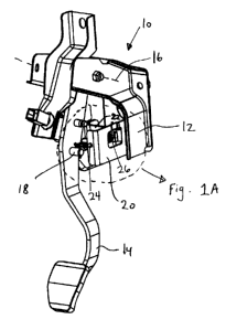
Fig_ 1 is a perspective view of a pedal assembly according to a preferred

embodiment of the invention;


Fig. IA is detailed view of the pedal assembly shown in Fig. 1;


Fig. 2 is fragmentary perspective view of the pedal assembly shown in Fig. 1,

with a bracket removed from the illustration;


Fig_ 3 is another fragmentary perspective view of the pedal assembly, with

brackets, pedals and other supporting structure removed from the illustration;
and


Fig. 4 is a graph showing the force vs. stroke profile of the preferred
embodiment in relation to a prior art over the center toggle mechanism_

Detailed Description of a Preferred Embodiment


Fig. 1 shows a pedal assembly 10 comprising a pedal lever 14 pivotally
mounted to a bracket 12 about axis 16 as well known in the art. A roller 18 is
mounted to the pedal lever 14.


The bracket 12 includes sub-brackets 20 and 22 which are rigidly connected to
bracket 12 to form a box-like enclosure. The sub-brackets 20, 22 carry a shaft
24
along an axis 25, which is oriented generally perpendicular to the pedal
rotational axis
16. A torsion spring 26 is mounted on the shaft 24. in addition, a cam 30 is
journal-
mounted to the shaft 24 so as to be rotatable about axis 25. As seen best in
Fig. 3, one


- 2 -

CA 02507660 2012-04-05


end 28 of spring 26 bears against the cam 30 and, as seen best in Fig. IA. thc
other
end 27 of the spring 26 bears against the sub-bracket 20.


The cam 30 features a cam profile 32;seen best in Fig. 3. The roller 18, which
functions as a cam follower, bears against the cam profile 32. When the pedal
is in
the rest position, the roller 18 is located in an initial position shown in
Fig. 3. Due to
the initial bulge 32A in the cam profile 32, activating the pedal lever 14
causes the
roller 18 to push the cam upward (in a direction generally transverse to both
axes 16
& 25) and twist spring 26. Consequently, a substantial force is required to
initially
activate the pedal. This force is related to the torsion characteristics of
the spring
rather the compression characteristics of the spring, and hence a generally
sharper
force vs, stroke profile 40 can be achieved, as seen in the comparison graph
of Fig. 4,
as compared to a prior art over-the-center toggle mechanism profile 42. Once
the
roller passes the bulge 32A, the spring 26 assists in the activation of the
pedal lever
14. However, unlike the prior art, the cam profile 328 enables the assist
force
provided by the torsion spring 26 to be tailored to a predetermined profile.


In alternative embodiments, a compression spring may be used instead of a
torsion spring. For example, a sub-bracket may be mounted above the cam with a
spring extending between the bracket and the cam that would be compressed as
the
cam pivots upward. Those skilled in the art will understand that a variety of
other
modifications may be made to the embodiments described herein without
departing
from the spirit of the invention.


- 3 -

Representative Drawing
A single figure which represents the drawing illustrating the invention.
Administrative Status

For a clearer understanding of the status of the application/patent presented on this page, the site Disclaimer , as well as the definitions for Patent , Administrative Status , Maintenance Fee  and Payment History  should be consulted.

Administrative Status

Title Date
Forecasted Issue Date 2013-05-21
(22) Filed 2005-05-16
(41) Open to Public Inspection 2005-11-14
Examination Requested 2010-05-04
(45) Issued 2013-05-21
Deemed Expired 2017-05-16

Abandonment History

There is no abandonment history.

Payment History

Fee Type Anniversary Year Due Date Amount Paid Paid Date
Application Fee $400.00 2005-05-16
Registration of a document - section 124 $100.00 2005-07-27
Maintenance Fee - Application - New Act 2 2007-05-16 $100.00 2007-03-22
Maintenance Fee - Application - New Act 3 2008-05-16 $100.00 2008-03-17
Maintenance Fee - Application - New Act 4 2009-05-19 $100.00 2009-03-17
Maintenance Fee - Application - New Act 5 2010-05-17 $200.00 2010-03-12
Request for Examination $800.00 2010-05-04
Maintenance Fee - Application - New Act 6 2011-05-16 $200.00 2011-03-22
Maintenance Fee - Application - New Act 7 2012-05-16 $200.00 2012-03-14
Final Fee $300.00 2013-02-04
Maintenance Fee - Application - New Act 8 2013-05-16 $200.00 2013-03-12
Maintenance Fee - Patent - New Act 9 2014-05-16 $200.00 2014-04-09
Maintenance Fee - Patent - New Act 10 2015-05-19 $250.00 2015-04-22
Owners on Record

Note: Records showing the ownership history in alphabetical order.

Current Owners on Record
INTIER AUTOMOTIVE CLOSURES INC.
Past Owners on Record
PODKOPAYEV, VADYM
Past Owners that do not appear in the "Owners on Record" listing will appear in other documentation within the application.
Documents

To view selected files, please enter reCAPTCHA code :


To view images, click a link in the Document Description column. To download the documents, select one or more checkboxes in the first column and then click the "Download Selected in PDF format (Zip Archive)" or the "Download Selected as Single PDF" button.

List of published and non-published patent-specific documents on the CPD .

If you have any difficulty accessing content, you can call the Client Service Centre at 1-866-997-1936 or send them an e-mail at CIPO Client Service Centre.


Document
Description 
Date
(yyyy-mm-dd) 
Number of pages   Size of Image (KB) 
Representative Drawing 2005-10-18 1 7
Abstract 2005-05-16 1 14
Description 2005-05-16 3 103
Claims 2005-05-16 1 19
Drawings 2005-05-16 5 101
Cover Page 2005-11-01 1 31
Claims 2012-04-05 2 48
Description 2012-04-05 3 89
Cover Page 2013-04-29 1 32
Correspondence 2005-06-27 1 25
Assignment 2005-05-16 3 98
Assignment 2005-07-27 3 81
Prosecution-Amendment 2010-12-09 1 28
Prosecution-Amendment 2010-05-04 1 28
Prosecution-Amendment 2011-10-06 2 67
Prosecution-Amendment 2012-04-05 7 193
Correspondence 2012-04-19 1 17
Correspondence 2012-04-19 1 18
Correspondence 2012-04-05 3 70
Correspondence 2013-02-04 2 43
Correspondence 2013-02-21 1 18
Correspondence 2013-02-21 1 17