Note: Descriptions are shown in the official language in which they were submitted.
CA 02507698 2005-05-30
WO 2004/056512 PCT/SE2003/001940
1
TITLE
A~-xangement for production of a three dimensional: object
TECHNICAL FIELD
The invention relates to an arrangement and a method for production of a
three-dimensional product by successive fusing together of selected parts of
powder layers applied to a work table.
BACKGROUND ART
An arrangement for producing a three-dimensional product by successive
fusing together of selected parts of powder layers applied to a work table is
previously known from, for example, US 4863538. The arrangement
comprises a work table on which said three-dimensional product is to be built
up, a powder dispenser which is arranged so as to distribute a thin layer of
powder on the work table for forming a powder bed, a radiation gun for
delivering energy to the powder, fusing together of the powder then taking
place, means for guiding the beam emitted by the radiation gun over said
powder bed for forming a cross section of said three-dimensional product by
fusing together parts of said powder bed, and a control computer in which
information about successive cross sections of the three-dimensional product
is stored. The three-dimensional product is built up by fusing together
selected parts of successive powder layers applied. The control computer is
intended to control deflection means for the beam generated by the radiation
gun over the powder bed according to an operating scheme which
reproduces a predetermined pattern. When the operating scheme has fused
together a desired area of a powder layer, a cross section of said three-
dimensional product has been formed. A three-dimensional product is
formed by successive fusing together of successively formed cross sections
from powder layers applied successively by the powder dispenser.
An arrangement for producing a three-dimensional product where
measurement of the surface structure and the surface temperature of the
CA 02507698 2005-05-30
WO 2004/056512 PCT/SE2003/001940
three-dimensional body produced is permitted during the manufacturing
procedure is known from SE 0001557-8. By using the arrangement
described therein, increased correspondence of the shape of the three-
dimensional bodies produced in relation to the intended shape is made
possible. In the process for manufacturing the three-dimensional products,
however, it has been found that surface stresses in the manufactured
product can give rise to shape deviations and also internal stresses in the
product which can give rise to the initiation of crack formation.
BRIEF DESCRIPTION OF THE INVENTION
One object of the invention is to provide a method for production of three-
dimensional bodies where reduction of induced shape deviations and of the
occurrence of internal stresses in the end product is made possible. This
object is achieved by an arrangement according to the characterizing part of
patent claim 1.
According to the method, the selected area of a powder bed corresponding
to a cross section of the three-dimensional body is divided into one or more
inner areas which each have an edge. The inner area is fused together in the
course of a movement pattern for the focal point of the beam of the radiation
gun which comprises a main movement direction and an interference term
which is added to said main movement direction and has a component in a
direction at right angles to the main movement direction. The interference
term has a time mean value corresponding to zero drift from the main
movement direction. The main movement direction has a propagation speed
which preferably corresponds to the propagation speed of a fusion zone of a
treated material. The main movement direction can have any curve shape,
for example rectilinear, curved, circular. The appearance of the main
movement direction is adapted to the shape of the object to be created.
However, the interference term is not adapted to the shape of the object but
is designed in order to provide a more favorable local heat distribution in an
CA 02507698 2005-05-30
WO 2004/056512 PCT/SE2003/001940
3
area around the focal point. The movement pattern of the beam thus ensures
that the energy of the radiation gun is supplied to the powder layer with more
uniform intensity, the risk of overheating being reduced. This in turn reduces
the risk of the appearance of shape deviations and stresses in the end
product. According to a preferred embodiment, the edge is fused together in
the course of a mainly rectilinear movement, which follows the shape of the
edge, of the beam of the radiation gun. By virtue of the edge being fused
together in the course of a movement which follows the shape of the edge, it
is ensured that the lateral surface of the finished body is smooth.
According to a preferred embodiment of the invention, an energy balance is
calculated for each powder layer, it being determined in the calculation
whether energy fed into the powder layer when said supply of energy from a
radiation gun according to an operating scheme determined for the powder
layer for fusing together that area of the powder layer selected according to
said operating scheme takes place is sufficient to maintain a defined working
temperature of the next layer. Information which makes it possible to
maintain a defined temperature is obtained through the balance calculation.
By maintaining a defined working temperature, that is to say a surface
temperature within a given defined temperature range, during the production
of all the layers, it is ensured that the occurrence of surFace stresses which
arise when cooling of the three-dimensional body is too great is reduced.
This in turn leads to the end product having a reduced occurrence of shape
deviations and also a reduced occurrence of internal stresses in the end
product.
Another object of the invention is to provide an arrangement for production of
three-dimensional bodies where reduction of the occurrence of surface
stresses and shape deviations induced by these and also the occurrence of
internal stresses in the end product is made possible. This object is achieved
by an arrangement according to the characterizing part of patent claim 5.
CA 02507698 2005-05-30
WO 2004/056512 PCT/SE2003/001940
4
In a preferred embodiment of the invention, the control computer included in
the arrangement is arranged so as to calculate an energy balance for each
powder layer, it being determined in the calculation whether energy fed into
the powder layer when said supply of energy from a radiation gun according
to an operating scheme determined for the powder layer for fusing together
that area of the powder layer selected according to said operating scheme
takes place is sufficient to maintain a defined working temperature of the
next layer. Information which makes it possible to maintain a defined working
temperature is obtained through the calculation. By maintaining a defined
working temperature, that is to say a surface temperature within a given
defined temperature range, during the production of all the layers, it is
ensured that the occurrence of surface stresses which arise when cooling of
the three-dimensional body is too great is reduced. This in turn leads to the
end product having a reduced occurrence of shape deviations and also a
reduced occurrence of internal stresses in the end product.
DESCRIPTION OF FIGURES
The invention will be described in greater detail below in connection with
accompanying drawing figures, in which:
fig. 1 shows a cross section of an arrangement according to the
invention,
fig. 2 shows an area to be fused together, which has an inner area
and an edge,
fig. 3 shows a set of different curve shapes with a one-dimensional
interference term,
fig. 4 shows diagrammatically how the heat distribution appears in a
body where the focal point with the diameter D of a radiation
CA 02507698 2005-05-30
WO 2004/056512 PCT/SE2003/001940
gun has heated the body, on the one hand in the presence of
an interference term, on the other hand in the absence of an
interference term,
5 fig. 5 shows an example of the movement of the focal point in
relation to movement of the focal point along the main
movement direction,
fig. 6 shows a set of different curve shapes with a two-dimensional
interference term,
fig. 7 shows the movement pattern of a focal point according to a
preferred embodiment of the invention,
fig. 8 shows the positioning of the focal points and also a widened
area within which fusing together takes place,
fig. 9 shows a further division of the area to be fused together into a
set of separate areas having respective inner areas and edges,
fig. 9a shows another division of the area to be fused together into a
set of separate areas having respective inner areas and edges,
fig. 10 shows diagrammatically a cross section of a three-dimensional
body formed by a number of powder layers and also a top
powder layer,
fig. 11 shows a schematic model for calculating energy balance,
fig. 12 shows another schematic model for calculating energy balance,
CA 02507698 2005-05-30
WO 2004/056512 PCT/SE2003/001940
6
fig. 13 shows a selected area which is divided into a set of separate
areas,
fig. 14 shows a view from the side of a chamber provided with a
transparent window,
fig. 15 shows an arrangement for feeding and fixing a protective film
for maintaining the transparency of the window,
fig.16 shows a flow diagram for generating primary operating
schemes,
fig.17 shows a flow diagram for an operating scheme of the
arrangement,
fig. 18 shows a flow diagram for correction of said operating scheme,
fig. 19 shows diagrammatically a procedure comprising correction of
operating schemes with the aid of information obtained from a
camera which measures the temperature distribution over the
surface of the powder bed,
fig. 20 shows diagrammatically a procedure for correction of operating
schemes,
fig.21 shows a diagrammatic construction of a three-dimensional
article, and
fig. 22 shows a number of cross sections from figure 21.
CA 02507698 2005-05-30
WO 2004/056512 PCT/SE2003/001940
7
MODES) FOR CARRYING OUT THE INVENTION
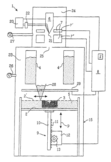
Figure 1 shows an arrangement for producing a three-dimensional product
generally designated by 1. The arrangement comprises a work table 2 on
which a three-dimensional product 3 is to be built up, one or more powder
dispensers 4 and also means 23 which are arranged so as to distribute a thin
layer of powder on the work table 2 for forming a powder bed 5, a radiation
gun 6 for delivering energy to the powder bed, fusing together of parts of the
powder bed then taking place, means 7 for guiding the beam emitted by the
radiation gun 6 over said work table for forming a cross section of said three-
dimensional product by fusing together said powder, and a control computer
8 in which information about successive cross sections of the three-
dimensional product is stored, which cross sections build up the three-
dimensional product. In a work cycle, the work table will, according to the
preferred embodiment shown, be lowered gradually in relation to the
radiation gun after each powder layer applied. In order to make this
movement possible, the work table is, in a preferred embodiment of the
invention, arranged movably in the vertical direction, that is to say in the
direction indicated by the arrow P. This means that the work table starts in a
starting position 2' in which a first powder layer of the necessary thickness
has been applied. So as not to damage the underlying work table and in
order to provide this layer with sufficient quality, this layer is thicker
than
other layers applied, fusing through of this first layer then being avoided.
The
work table is subsequently lowered in connection with a new powder layer
being distributed for forming a new cross section of the three-dimensional
product. In one embodiment of the invention, the work table is to this end
supported by a stand 9 which comprises at least one ball screw 10, provided
with toothing 11. A step motor or servomotor 12 provided with a gearwheel
13 sets the work table 2 to the desired vertical position. Other arrangements
known to the expert for setting the working height of a work table can also be
used. Adjusting screws, for example, can be used instead of racks.
According to an alternative embodiment of the invention, means for powder
CA 02507698 2005-05-30
WO 2004/056512 PCT/SE2003/001940
8
distribution included in the arrangement can be raised gradually instead of
lowering the work table as in the embodiment described above.
The means 28 is arranged so as to interact with said powder dispensers for
replenishment of material. Furthermore, the sweep of the means 28 over the
working surface is driven in a known manner by a servomotor (not shown)
which moves the means 28 along a guide rail 29 which runs along the
powder bed.
When a new powder layer is applied, the thickness of the powder layer will
be determined by how much the work table has been lowered in relation to
the previous layer. This means that the layer thickness can be varied
according to repuirements. It is therefore possible, when a cross section has
a great change in shape between adjacent layers, to make thinner layers, a
higher surface fineness then being achieved, and, when there is little or no
change in shape, to make layers with maximum penetration thickness for the
beam.
fn a preferred embodiment of the invention, the radiation gun 6 consists of an
electron gun, the means 7 for guiding the beam of the radiation gun
consisting of deflecting coils 7". The deflecting coil 7" generates a magnetic
field which guides the beam produced by the electron gun, it then being
possible for fusion of the surFace layer of the powder bed in the desired
location to be brought about. The radiation gun also comprises a high-
voltage circuit 20 which is intended to provide the radiation gun in a known
manner with an acceleration voltage for an emitter electrode 21 arranged in
the radiation gun. The emitter electrode is in a known manner connected to a
current source 22 which is used to heat the emitter electrode 21, electrons
then being released. The functioning and composition of the radiation gun
are well-known to an expert in the field.
CA 02507698 2005-05-30
WO 2004/056512 PCT/SE2003/001940
9
The deflecting coil is controlled by the control computer 8 according to an
operating scheme laid out for each layer to be fused together, it then being
possible to guide the beam according to a desired operating scheme. Details
of the appearance according to the invention of the operating scheme are
described below in connection with the description of figures 2-9.
Also present is at least one focusing coil T which is arranged so as to focus
the beam on the surface of the powder bed on the work table. Deflecting
coils 7" and focusing coils T can be arranged according to a number of
alternatives well known to the expert.
The arrangement is enclosed in a casing 15 which encloses the radiation
gun 6 and the powder bed 2. The casing 15 comprises a first chamber 23
which surrounds the powder bed and a second chamber 24 which surrounds
the radiation gun 6. The first chamber 23 and the second chamber 24
communicate with one another via a passage 25 which allows emitted
electrons, which have been accelerated in the high-voltage field in the
second chamber, to continue into the first chamber, subsequently to strike
the powder bed on the work table 2.
In a preferred embodiment, the first chamber is connected to a vacuum
pump 26 which lowers the pressure in the first chamber 23 to a pressure of
preferably roughly 10~ - 10-5 mbar. The second chamber 24 is preferably
connected to a vacuum pump 27 which lowers the pressure in the second
chamber 24 to a pressure of roughly 10-4 - 10'6 mbar. In an alternative
embodiment, both the first and second chambers can be connected to the
same vacuum pump.
The control computer 8 is furthermore preferably connected to the radiation
gun 6 for regulating the output of the radiation gun and also connected to the
step motor 12 for adjusting the vertical position of the work table 2 between
CA 02507698 2005-05-30
WO 2004/056512 PCT/SE2003/001940
consecutive applications of powder layers, it then being possible to vary the
individual thickness of the powder layers.
The control computer is also connected to said means 28 for powder
5 distribution on the working surface. This means is arranged so as to sweep
over the working surface, a layer of powder being distributed. The means 28
is driven by a servomotor (not shown) which is controlled by said control
computer 8. The control computer controls the sweep along and ensures that
powder is replenished as required. For this reason, load sensors can be
10 arranged in the means 28, the control computer then being able to obtain
information about the means being empty or having become stuck.
According to a preferred embodiment of the invention, the control computer 8
is also arranged so as to calculate an energy balance for the selected area
to be treated within each powder layer, it being determined in the calculation
whether energy radiated into the selected area from the surroundings of the
selected area is sufficient to maintain a defined working temperature of the
selected area.
According to the invention, the operating scheme is designed in such a way
that the area to be fused together, that is to say the selected area, is
divided
into one or more inner areas I, each having an edge R. Figure 2 shows
diagrammatically an area 35 to be fused together. The area comprises an
inner area I delimited by an edge R. According to the invention, the inner
area I is fused together using a movement pattern for the focal point of the
beam of the radiation gun which comprises a main movement direction and
an interfierence term which is added to said main movement direction and
has a component in a direction at right angles to the main movement
direction. The interference term changes direction and has a time mean
value corresponding to zero drift from the main movement direction. Figure 3
shows three different examples of different appearances of the interference
CA 02507698 2005-05-30
WO 2004/056512 PCT/SE2003/001940
11
term which give rise to a movement in the form of a triangular wave, a
sinusoidal curve and a square wave.
Figure 4 shows diagrammatically how the heat distribution appears in a body
where the focal point with the diameter D of a radiation gun has heated the .
body. The temperature distribution around the focal point has the shape of a
Gaussian bell. The temperature distribution around a focal point without
interference term is shown by the curve marked (a). By means of the
interference term, the trace treated in the course of propagation of the beam
along the main movement direction is widened. A widened trace is shown by
the curve indicated by (~3). The widened trace also has a temperature
distribution with a lower maximum value. This reduces the risk of the
appearance of overheating with the formation of irregularities as a
consequence.
The interference term is preferably of such a nature that a fusion zone is
formed which has a width essentially corresponding to twice the amplitude of
the component of the interference term in a direction at right angles to the
main movement direction. The average speed of the absolute value of the
movement of the focal point in the direction of the interference term is
preferably to exceed the speed of the heat propagation in the material. The
speed in the main movement direction preferably corresponds to the speed
of the heat propagation in the material. The amplitude and the frequency of
the interference term are preferably to be adapted in such a way that the
focal point is able to move from its starting position where the interference
term has the value zero, pass through the minimum and the maximum value
of the interference term and return to its position in the time it takes the
wave
front of the heat propagation to move from the first zero position to the
second zero position. This is shown diagrammatically in figure 5. Figure 5
shows how the focal point moves along the curve 50 from a first position 51,
past a maximum 52 of the interference term, a minimum 53 of the
CA 02507698 2005-05-30
WO 2004/056512 PCT/SE2003/001940
12
interference term and then takes up a second position 54 with a zero value
of the interference term. During this time, the wave front of the heat
propagation has been propagated from the first position 51 to the second
position. If the average speed of the interference term is too low, a curved
fused trace which runs within the path defined by the end points of the
interference term is formed instead of a wide trace.
According to a preferred embodiment, the interference term also has a
component in a direction parallel to the main movement direction. The ,
interference term is in this case two-dimensional. Examples of interference
terms with a two-dimensional direction are given in figure 6.
The edge R is preferably fused together in the course of a mainly rectilinear
movement of the beam of the radiation gun.
The purpose of operating with a movement pattern for the focal point of the
beam of the radiation gun which comprises a main movement direction and
an interference term added to said main movement direction which has a
component in a direction at right angles to the main movement direction is
that, with a wider trace, it is possible to move the fusion zone more slowly
but
still fuse at a relatively high speed compared with conventional operation.
Slow movement of the fusion zone produces less vaporization and a reduced
incidence of fused material boiling and splashing. The purpose of the edge
being fused together using a continuous mainly rectilinear movement is that
this produces a smooth surface structure for the finished product.
An analysis of the movement pattern for the beam of the radiation gun in the
case of a preferred embodiment of the invention with a two-dimensional
interference term, which gives rise to a helix-like movement pattern of the
focal point, follows below.
CA 02507698 2005-05-30
WO 2004/056512 PCT/SE2003/001940
13
The position of a focal point which rotates about the x axis and moves along
the same axis at the speed V,~ can be obtained from:
r~r~ = (~'xr+.~x coS(~~~)x+,~u ~In~c~'~y~
Equ. 1
where AX and Ay are the amplitudes in the x and y direction respectively.
A typical "spinning curve" can appear like that shown in figure 4.
The pattern shown in figure 7 is obtained if e~ is set to:
~x
Equ. 2
The speed of the focal point is given by:
G~t"~~~ i ~~x ~ Axfr~ 5i~1,~~~~ -~ ~.~,~rl GC~S~Wt~,~
d~
Equ. 3
Its absolute speed is therefore:
dr(t) ~ ~~ _ ~r~?Sm(Wf)~~ ~-(r4y,traCOS(~7~'~)'
df
Equ. 4
CA 02507698 2005-05-30
WO 2004/056512 PCT/SE2003/001940
14
If the focal point moves according to the formulas above, its speed will vary
and either be at a maximum underneath the x axis and a minimum above or
vice versa depending on the direction of rotation. In order to obtain a focal
point which moves at constant speed along the spinning curve in figure 1, its
average speed is first calculated:
dt
T
Equ. 5
Where:
~, _ 2~c
Vaverage is the speed at which the focal point is to move. At the time t, the
focal
point has moved the distance:
S = t Vaverage
This distance must be equal to the spinning curve length at the time t'.
Therefore:
Ti '" drat) r
~' average-
° Equ. 6
Solving Equ. 6 for 0<t<T gives t' as a function of t. t' is then used in Equ.
1
which gives the position of the spot as a function of the time t.
A number of simulations using different speeds and Ay has shown that the
fusion zone 0.1-0.15 mm below the surface has an approximate width of
1.8Ay. The hop between two spin lines should then be:
CA 02507698 2005-05-30
WO 2004/056512 PCT/SE2003/001940
Hop spin=1.BAy 0.3
The distance to the start from an edge is approximately:
5
Starting hop=0.8Ay 0.15
Figure 8 shows a continuous wide fused edge which propagates in the
direction x marked by an arrow in the diagram. The focal points with a
10 diameter D are marked in the diagram. The overlapping pattern ensures that
fusing together takes place within an area outside the focal point. Such an
area is illustrated and marked by the symbol b. Together, these areas form
an overall area which propagates in the direction marked by the arrow x.
15 Figure 9 shows diagrammatically an area 35 to be fused together. This area
is divided into a number of part areas 80-91 which each have an inner area
and an edge.
According to a preferred embodiment of the invention, the operating scheme
is designed in such a way that the inner area I of a set of adjacent part
areas
is fused together in the course of a movement pattern for the focal point of
the beam of the radiation gun which comprises a main movement direction
and an interference term which is added to said main movement direction
and has a component in a direction at right angles to the main movement
direction. At least that edge which forms an inner or outer lateral surface of
the finished body is preferably fused together in the course of a movement
which follows the edge without addition of an interference term. According to
one embodiment of the invention, the inner areas I are fused together in a
first process step, after which the edges join together the inner areas in a
subsequent process step. By means of this procedure, the occurrence of
bending stresses in the three-dimensional body after cooling is reduced. In
an alternative embodiment, the edges can be fused together in a first
CA 02507698 2005-05-30
WO 2004/056512 PCT/SE2003/001940
16
process step and the inner areas in a subsequent process step. This can be
advantageous when very thin powder layers are distributed, a solid lateral
surface being created, if appropriate with a number of inner supporting
partitions. The inner areas can then be fused together in a subsequent
process step where several powder layers are fused together in a common
sweep of the radiation gun over several layers. This results in the inner
areas
being lightly sintered, which can be advantageous for certain products.
According to a preferred embodiment of the invention, the control computer
is also arranged so as to calculate an energy balance for at least the
selected area to be fused together within each powder layer, it being
determined in the calculation whether energy radiated into the selected area
from the surroundings of the selected area is sufficient to maintain a defined
working temperature of the selected area.
The purpose of calculating the energy balance for the powder layers is to
calculate the power required in order to keep the surface of the object at a
given temperature. The power is assumed to be constant over the entire
surface:
How the energy balance calculation is performed in an embodiment of the
invention where the calculation is performed for one layer at a time is
described below.
In order for it to be possible to calculate the power in real time,
simplifications
are necessary:
1. We imagine that the temperature is constant in the x and y directions
and that it varies only in the z direction, in other words the entire
surface has the same temperature.
2. The temperature in the z direction varies with jLt, where j is the layer
number and Lt is the layer thickness.
CA 02507698 2005-05-30
WO 2004/056512 PCT/SE2003/001940
17
3. The temperature distribution during fusion is assumed to be
stationary.
The following parameters have an effect on the calculation:
Various indexes:
i = index for the top layer
j = layer index goes from 1 to i
Object data:
Lt = layer thickness to be fused [m]
Lcont(~) = contour length for layer j [m]
Apov~rt(z) = Apovir(j) = area facing the powder for layer j [m]
A(z) = A(j) total surface area fused for layer j [m2]
Material properties:
amef = thermal conductivity of the material [W/mK]
6met = radiation constant for the metal surface [W/m2K]
~metpow = radiation constant for metal surface covered with powder [W/m2K]
~pow = radiation constant for the powder surface [W/m2K]
~,poW = thermal conductivity of the powder [W/mK]
hPoW(z) = heat transfer coefficient from the object out to the powder [W/m2K]
a = proportion of the radiation power taken up by the material
Temperatures [K]:
Tsur(i) = temperature of the surroundings affecting the surface when layer i
is fused (can be measured on the heating shield)
Tpow(z) = temperature in the powder
T(z) = temperature in the object
Tsurf(i) = T(iLt) = desired temperature on the surface of the object when
layer i is fused. (Is set in AMA)
CA 02507698 2005-05-30
WO 2004/056512 PCT/SE2003/001940
18
Tbott(i) = temperature at the bottom of the object before layer i is started
(Is
measured just before raking or is calculated. See below.)
In order to determine how the temperature is distributed in the object, we
solve the one-dimensional stationary thermal conductivity equation including
a source term which takes account of heat losses out into the powder:
~~~'~z) ~ h~",(z),~P~.v(z),
- ~',~~~ ~, ~(z)~t (Tpou~(z) ~- 2'{z~)
The boundary conditions on the surFace and at the bottom are:
~ ~~~~ ~t=1Gt - ~~mer ~ 6pow ~ (~(l.~.t~~ ~ ~JIIt'(1~~ ) " ~~~t,~.t~
met 1.
-~'mec d ~,~, ~ ~c~0'" ~pow~~O~f~7) - f (0~~
Where A and 8 are two constants.
Rewrite the formulas as differential formulas instead and let j be indexed for
each layer.
-~ T(j+2)-2l'(j+I)+T(.l) ~ haow~I)~Po'y(J) (x.~ow -T )
R(j)zx (j) (j)
_ ~-"m"'~J (~"(l) - ~('(i _ 1)) _ (diner + ~YOw) (~,(1).4 _ TSZIY(%)~ ) - pn
Lt Z A(i)
- ~~' (T(2)-T(1))=ray~w(Tbozt(i)-T(1))
where
1 <_j5i-2
CA 02507698 2005-05-30
WO 2004/056512 PCT/SE2003/001940
19
The boundary condition on the surface actually provides us with nothing new
as far as the temperature distribution in the object is concerned as the
temperature of the surface is determined by T(i). But it is required in order
to
determine Pin which is the power necessary in order to keep the temperature
on the surface at T(i). T~) is now obtained from the following equation
system:
d(.I) _ ~oow(~)AP~~'tJ~Lt
~~,~ )~'nru
T( j ~r 2) -. 2T( j + 1) + T( j)(1 + d( j)) = ~(l ).~P~~'E.J)
T(i) = Tbott (i) h~1~" ~l)~'t/'~~rr:r + T(~) 1
t~, + lfpow (i~~'l /I~'nlef ) (i + h pow (i)Lt ~~atrr )
Insert the expression pressure for T(1 ) and formulate the problem as a linear
equation system:
1. T(3)_~-~(Z)+T(Z) (1+A(1)) ~~(I)Tp~(1)_~ott(i) "po,.wL=~~."~.r (1+D(1))
(1 +hpe,. (1)Zt/~m~r ) ~ +hpow(r)Zt/~ma )
2. T(4)-2~'(3)+T(2)(I+~(2))=e(2)T'pow(2)
i-2. -2Z(i-1)+T(i-2)(I+G1(i-2))=~(i-2)Tpow(i-2)-T(~)
In matrix form this becomes:
Ax = b
where then:
AJx =tS(j+1-k)-a~'(j--k)+~(j-1-k)(~+~1(j))+8(i-k)8(1--J~ (i+C1(i))
() -1- hyaw (1)~t~~~~~r )
x~ sT(2),.....,x;_~ ='~(i-T)
bj = a(.~)Tp~~7 - ~~ - 1)~~~t (J~ hPow(i)L~/~mcr (~ -~ ~~~))'"' ffitJ " I +
2)T(J)
(i + hPoW (1.)Lt~~.nrrr
CA 02507698 2005-05-30
WO 2004/056512 PCT/SE2003/001940
In order for it to be possible to solve the equations, it is necessary that
the
temperature of the powder, Tpow~), and the heat transfer coefficient, hpow~),
are known. In the program, Tpow(z) is set to:
Tpow( j) = AT( j)i_1 + BTsu~(i -1)
5 i-1 means that the temperature for the previous layer is used in order to
determine Tpow(~).
The function used for hPoW(~) looks like this:
~,
10 The values L1 and L2 have been assumed to be area-independent while
hconst1, hconst2 and hconst3 are assumed to depend on A(~). All the
constants in the expressions for both Tpow and hpow have been produced
by adapting the 1 D model above to 3D FEM calculations on objects with
simple geometries.
Included in the expression for the source term is Apovv~) which is actually
the
total area facing the powder for each layer. In the case of large area
transitions, this value may be very great, which means that the value of the
source term jumps. Such discrete jumps make the solution unstable. In order
to prevent this, according to a preferred embodiment, Apow(~) is set to
Leont(~)*Lt. Power losses which arise owing to an area transition are instead
L~Y~. ~ l.7
CA 02507698 2005-05-30
WO 2004/056512 PCT/SE2003/001940
21
added afterwards. The size of the power loss depends on how large over the
respective underlying area the area transition is and how far below the top
layer it is located. The values for different area transitions and different
depths have been produced by 3D FEM simulations. For an arbitrary area
transition, the additional power is obtained by interpolation.
Before the power is calculated, the program reads the various values for
Lcont~)*Lt and A(~) for each layer. With the aid of a script file, these can
be
influenced in various ways. In this way, it is possible to control the power
for
each layer. How the various geometry parameters are influenced emerges
from the description of how the script file functions.
When the equation system above is solved, the total power required in order
to keep the surface at Tsuri(i) is obtained from the boundary condition for
the
surface:
~~r~-~.~Z~_T~t'~~~'i'~~nrar ~~pcw~~~.~1~~,_,T'.STIT{l~a~~
When a layer is fused, use is made of different current and speed over the
surface. In order for it to be possible to calculate the different currents
required, the mean value of all powers used is set equal to Pin.
If a layer is to be fused using n, different currents, then:
k~,Nr
~ik~l~
~',.~ ~ ail' ~~~
~ar
'~J~C
~ik
k=n~
Tor ~ ~'~It~
k~.L
CA 02507698 2005-05-30
WO 2004/056512 PCT/SE2003/001940
22
Where tk is the fusion time for each current I;k
I;~ is the fusion length
vk is the fusion speed
Tfof is the total fusion time for the layer i
U is the acceleration voltage.
In order for it to be possible to calculate the currents, the speeds must
therefore be known. These are obtained from what are known as speed
functions which indicate the relationship between current and speed. As
these functions are not analytical, an iterative procedure must be used in
order to determine all the currents and speeds. In the calculation program,
each starting value of I;~ is guessed. The various speeds are then obtained.
The values of the currents are then increased until the mean value of the
power just exceeds the calculated value of Pin.
Assume now that we want to fuse the various part areas at such a speed
and current that the energy which is delivered to the material is less than
that
required in order to keep the surface at Tsurf(i). The surface must then be
heated. The number of times required in order to heat the surface is obtained
by adding a heating term in the expression for the mean value of the power:
3~ C~~ ~»a~~r hcart
~3t~~r ~ ~!
,~a~~~xt
t
and adding the heating time in the expression for the time Trot:
CA 02507698 2005-05-30
WO 2004/056512 PCT/SE2003/001940
23
~~~~~ r~~
~S~ur
where n indicates how many times the surface has to be heated.
The calculation routine shown above can be used for the entire powder
layer. In an alternative embodiment, calculation can be carried out for
various
part areas of the powder layer. The equations indicated above can be used
in this case as well. However, different boundary conditions are obtained for
the inner edges which lie close to a fused body.
Figure 10 shows a side view of a fused-together body 30 which is built up by
fusing together part areas 31-34 in consecutive powder layers i-1, i-2, i-3, i-
4.
A real body manufactured according to the invention can of course have
many more layers than indicated in this example. A top powder layer i is
distributed on the body. Located within this top powder layer is a selected
area 35. The selected area 35 consists of the area which, according to an
operating scheme, is to be fused together. The selected area 35 within the
layer i is delimited by an outer edge 36. It is of course conceivable for a
selected area to comprise both outer and inner edges. The balance
calculation is to be perFormed on the entire selected area 35. The selected
area 35 is preferably divided into a plurality of smaller part areas as shown
in
figure 9, it then being possible for separate calculations to be perFormed for
the part areas. Within the selected area 35, a part area 37 is shown, for
which an energy balance is to be calculated. The part area 37 can consist of
a part of the selected area as shown in figure 5 or alternatively can consist
of
the entire selected area.
Figure 9a shows a selected area 35 which is divided into a plurality of
smaller part areas. According to a preferred embodiment of the invention, the
CA 02507698 2005-05-30
WO 2004/056512 PCT/SE2003/001940
24
surface within each powder layer is divided into a set of separate areas 38
53 which each comprise some part of the selected area 35, an energy
balance being calculated for each of said set of separate areas 38-53. The
selected area is delimited by an outer edge 72. The selected area can of
course also comprise inner edges.
According to another preferred embodiment of the invention, said set of
separate areas 38-53 comprises a first group of areas 54-58 of which the
edges lie entirely within the selected area 35 and a second group of areas
38-53 of which the edges coincide at least in part with the edge 72 of the
selected area. Where appropriate, the areas within said second group of
areas can be divided into sub-areas 38a, 39b; 48a-48d. Each of the part
areas 54-58 making up said first group of areas preferably has the same
shape. In the example shown, the areas are square. Rectangular, triangular
and hexagonal areas can advantageously be used. Boundary conditions
within this group are also similar apart from possible temperature
differences.
The use of likeness of shape allows the calculation routines to be simplified
as in part common calculations can be performed.
The energy balance is calculated in principle according to E'" (i) = E~Ut (i)
+
Eneat(i)~ where E'" (i) represents energy fed into the part area, E~ut (i)
represents energy losses through dissipation and radiation from the part
area, and Eheat(i) represents stored in the part area. The energy fed in
consists of on the one hand energy E~" c°~ which has been radiated in
or has
flowed in via thermal conduction from the surroundings of the part area 35
for which the energy balance is calculated and on the other hand of energy
E'" ~S> which has been radiated in from the radiation gun 6. If the energy
balance is calculated before energy has been supplied to the part area 35,
E~n csa therefore = 0. According to a preferred embodiment of the invention,
at
least a first energy balance calculation is performed for the part area 35
before energy has been supplied via the radiation gun 6.
CA 02507698 2005-05-30
WO 2004/056512 PCT/SE2003/001940
Figure 11 shows diagrammatically a model on which the calculation of the
energy balance for the part area 0~ is based. In this case, the part area ~~
corresponds to a part of the selected area of the powder layer i. In this
case,
the equation for calculation of the energy balance has the appearance E'"
5 (~~) = E°ut (d~) + Eneat(0~), where E'" (0,) represents energy fed
into the part
area, E°~t (~,) represents energy losses through dissipation and
radiation
from the part area ~~ and E"eat(,) represents stored in the part area 0,. The
energy fed in consists of on the one hand energy E'" c°> (~,) which has
been
radiated in or has flowed in via thermal conduction from the surroundings of
10 the part area 0~ and on the other hand of energy E'" ~S~ ~~ which has been
radiated in from the radiation gun 6.
Figure 12 shows diagrammatically a model on which the calculation of the
energy balance for a second part area ~2 within the selected area 35 in the
15 layer i is based. In this case, the part area ~~ corresponds to a part of
the
selected area 35 of the powder layer i which has not yet been fused together
and which is adjacent to a first part area ~, within the powder layer i, where
radiation or thermal conduction takes place from said first to said second
part
area. In this case, the equation for calculation of the energy balance has the
20 appearance E'" (~2) = E°~t (~2) + E"eat(~~), where E'" (d2)
represents energy fed
into the part area, E°"t (02) represents energy losses through
dissipation and
radiation from the part area ~, and E"eat(~2) represents stored in the part
area
02. The energy fed in consists of on the one hand energy E'" ~°~ (~2)
which has
been radiated in or has flowed in via thermal conduction from the
25 surroundings of the part area 0, and on the other hand of energy E'" ~S~ 02
which has been radiated in from the radiation gun 6. The energy E'" ~°>
(02)
supplied via thermal conduction comprises the component E'" ~S~ (02, i-1 )
which corresponds to energy supplied from the previous layer and also
E°~t
(~,, D2) which corresponds to energy which has been dissipated or radiated
from the first part area 0, and supplied to the second part area d2.
CA 02507698 2005-05-30
WO 2004/056512 PCT/SE2003/001940
26
According to fig. 13, the arrangement also comprises, according to a
preferred embodiment of the invention, means 14 for sensing surface
properties of a surface layer located in the powder bed. This means 14 for
sensing the temperature distribution of a surface layer located in a powder
bed 5 preferably consists of a camera. In a preferred embodiment of the
invention, the camera is used on the one hand to measure the temperature
distribution on the surface layer and on the other hand to measure the
occurrence of surface irregularities by means of the shadow formation to
which surface irregularities give rise. On the one hand, information about the
temperature distribution is used to bring about as uniform a temperature
distribution as possible over those parts of the surface layer which are to be
fused and, on the other hand, information can be used in order to check for
any dimensional deviations between generated three-dimensional product
and original design as the temperature distribution reflects the shape of the
product. In a preferred embodiment of the invention, the video camera is
mounted on the outside of the casing 15 which encloses the powder bed 5
and the radiation gun 6. In order to make temperature measurement
possible, the casing is provided with a transparent window 16. The powder
bed 5 is visible for the camera through this window.
In a preferred embodiment of the invention, which is shown in figure 14, the
window 16 is covered by a protective film 17. The protective film is fed from
a
feed-out unit 18 to a collecting unit 19, the film being gradually replaced,
which means that the transparency can be maintained. The protective film is
necessary as coatings form as a consequence of the fusion process.
A detailed description relating to generating and correcting operating
schemes follows below in connection with the description of drawing figures
15-.
CA 02507698 2005-05-30
WO 2004/056512 PCT/SE2003/001940
27
Figure 12 shows diagrammatically a method of producing three-dimensional
bodies according to the invention. The three-dimensional body is formed by
successive fusing together of selected areas of a powder bed, which parts
correspond to successive cross sections of the three-dimensional body.
In a first method step 100, application of a powder layer to a work table
takes
place. Application is effected by the means 28 mentioned above distributing
a thin layer of powder on the work table 2.
In a second method step 110, energy is supplied from a radiation gun 6,
according to an operating scheme determined for the powder layer, to a
selected area within the powder layer, fusing together of the area of the
powder layer selected according to said operating scheme then taking place
to form a cross section of said three-dimensional body. A three-dimensional
body is formed by successive fusing together of successively formed cross
sections from successively applied powder layers. The successive cross
sections are divided into one or more inner areas I, each having an edge R,
where, according to the invention, the inner area I is fused together in the
course of a movement pattern for the focal point of the beam of the radiation
gun which comprises a main movement direction and an interference term
which is added to said main movement direction and has a component in a
direction at right angles to the main movement direction. According to a
preferred embodiment, the edge is fused together in the course of a mainly
rectilinear movement of the beam of the radiation gun.
In a preferred embodiment, an energy balance is calculated in a third method
step 120 for at least the selected area to be fused together within each
powder layer, it being determined in the calculation whether energy radiated
into the selected area from the surroundings of the selected area is
sufficient
to maintain a defined working temperature of the selected area. Calculation
is performed according to the models indicated above.
CA 02507698 2005-05-30
WO 2004/056512 PCT/SE2003/001940
28
Figure 16 shows diagrammatically the procedure for generating primary
operating schemes. In a first step 40, a 3D model is generated, in a CAD
program for example, of the product to be manufactured, or alternatively a
ready-generated 3D model of the product to be manufactured is input into
the control computer 8. Then, in a second step 41, a matrix containing
information about the appearance of cross sections of the product is
generated. Figure 21 shows a model of a hammer with examples of
associated cross sections 31-33. These cross sections are also shown in
fig. 22a-22c. The cross sections are distributed with a density corresponding
to the thickness of the various layers to be fused together in order to form
the
finished product. The thickness can advantageously be varied between the
various layers. It is inter alia advantageous to make the layers thinner in
areas where there is great variation in the appearance of the cross sections
between adjacent layers. When the cross sections are generated, a matrix
containing information about the appearance of all the cross sections which
together make up the three-dimensional product is therefore created.
Once the cross sections have been generated, a primary operating scheme
is generated for each cross section in a third step 42. Generation of primary
operating schemes is based on shape recognition of the parts which make
up a cross section on the one hand and knowledge of how the operating
scheme afFects the cooling temperature of local parts of a cross section on
the other hand. The aim is to create an operating scheme which allows the
cooling temperature to be as uniform as possible in the parts which are fused
together before the next layer is applied at the same time as the cooling
temperature is to be kept within a desired range in order to reduce the risk
of
shrinkage stresses appearing in the product and to reduce the magnitude of
shrinkage stresses which have arisen in the product, with deformation of the
product as a consequence.
In the first place, a primary operating scheme is generated on the basis of
the shape of separate component parts of the cross section. When
CA 02507698 2005-05-30
WO 2004/056512 PCT/SE2003/001940
29
generation takes place, the edge and the inner area of each cross section
are identified. Where appropriate, a set of inner areas which each have
edges is formed. According to the invention, an operating scheme is
generated for the inner areas which has a movement pattern for the focal
point of the radiation gun which comprises a main movement direction and
an interference term which is added to said main movement direction and
has a component in a direction at right angles to the main movement
direction as indicated above. At the edges, the focal point of the radiation
gun moves in a mainly linear movement pattern. This means that the
radiation gun follows the shape of the edge.
In a preferred embodiment of the invention, primary operating schemes are
therefore laid out on the basis of experience of which operating schemes
provide a good temperature distribution of the cooling temperature of the
cross section, it then being possible for the risk of shrinkage stresses in
the
product with deformation of the product as a consequence to be reduced. To
this end, a set of operating schemes for areas of different shapes is stored
in
a memory. The operating schemes according to the invention are designed
in such a way that the focal point of the radiation gun, within inner areas I,
moves in a movement pattern which comprises a main movement direction
and an interference term which is added to said main movement direction
and has a component in a direction at right angles to the main movement
direction. In addition to this information, the operating schemes can comprise
a list of the order in which a set of inner areas is to be treated,
information
about heating different areas and information about energy supply and
sweep speed. In a preferred embodiment, this memory is updated as results
of corrections of the operating scheme are evaluated, a self learning system
being obtained.
In an alternative embodiment of the invention, ready-finished cross sections,
which have been generated by a stand-alone computer, are input into a
memory in the control computer, where said primary operating schemes are
CA 02507698 2005-05-30
WO 2004/056512 PCT/SE2003/001940
generated. In this case, information is provided directly to the third step 42
via an external source 40a.
Figure 17 shows diagrammatically a procedure for generating a three-
5 dimensional body, which comprises method steps for calculating an energy
balance for a layer. In a first method step 130, parameters on which an
energy balance calculation is based are determined. In a second method
step 140, calculation of the energy balance for at least the selected area 35
takes place. Calculation is performed according to the method illustrated
10 previously.
In a third method step 150, the operating scheme is updated depending on
the calculated energy balance. If the result of the energy balance is that
sufficient heat energy is stored in the selected area to maintain a desired
15 working temperature, no extra energy supply takes place. According to one
embodiment of the invention, if the result of the energy balance is that
sufficient heat energy to maintain a desired working temperature is not
stored in the selected area, an extra energy supply takes place in the form of
preheating of the selected area before fusing together takes place. This
20 preheating can be effected by the radiation gun being swept very rapidly
over the area or the radiation gun sweeping over the area with lower power
than normal, or alternatively a combination of both of these. The preheating
takes place in a fourth method step 160.
In a fifth method step 170, fusing together is effected by the radiation gun
25 sweeping over the selected area.
Figure 18 shows diagrammatically an embodiment of the invention which,
where appropriate, utilizes the methods described above for generating and
correcting the operating schemes. In a first method step 180, one or more of
30 the inner areas I of the selected area are identified. In a second method
step
190, the edge or edges R which are associated with said inner areas and
each surround said inner areas are identified. In a third method step 200,
CA 02507698 2005-05-30
WO 2004/056512 PCT/SE2003/001940
31
said inner areas I are fused together in the course of a partly overlapping
circular movement of the beam emitted by the radiation gun. During a fourth
method step 210, said edges are fused together in the course of a rectilinear
movement of the beam. The magnitude of the correction is smaller for
processes which use the method according to the invention with a movement
pattern having an interference term and also for processes where an energy
balance calculation is performed. A correction can nevertheless be used in
order further to improve the end result.
According to one embodiment of the invention, the operating scheme is
arranged so as consecutively to fuse together the powder within one area at
a time within said inner areas.
According to a preferred embodiment of the invention, the control computer
is arranged so as to divide the surface within each powder layer into a set of
separate areas, said set of separate areas comprising a first group of areas
which lie entirely within the edge of said selected area and a second group of
areas of which the edges coincide in part with the edge of said selected
area. Where appropriate, the areas within said second group of areas can be
divided into sub-areas. Each of the part areas making up said first group of
areas preferably has the same shape. In the example shown, the areas are
square. Rectangular, triangular and hexagonal areas can advantageously be
used. Boundary conditions within this group are also similar apart from
possible temperature differences. The use of likeness of shape allows the
calculation routines to be simplified as in part common calculations can be
performed.
The control computer is also arranged so as to ensure that said inner areas
of a set of areas within said first group of areas are fused together in the
course of a partly overlapping circular movement of the beam of the radiation
gun.
CA 02507698 2005-05-30
WO 2004/056512 PCT/SE2003/001940
32
In one embodiment of the invention, the fusing together of the inner areas in
said second group of areas takes place with a focal point movement
comprising an interference term as described above. In an alternative
embodiment of the invention, the fusing together within the inner areas in
said second group of areas takes place with a mainly rectilinear movement.
According to a preferred embodiment of the invention, in the case of the
embodiments described above relating to division of the selected surface
into smaller part surfaces, the calculation of energy balance described above
is used in order to control the operating scheme with regard to calibration of
the power of the beam and supply of energy for heating the powder bed
before final fusing together takes place.
Figure 19 shows diagrammatically a procedure comprising correction of
operating schemes with the aid of information obtained from a camera which
measures the temperature distribution over the surface of the powder bed.
According to the procedure, the beam from the radiation gun is guided over
the powder bed in order to generate a cross section of a product. In a first
step 50, guidance of the beam over the powder bed according to the primary
operating scheme defined in step 42 is started. In the next step 51, the
temperature distribution on the surFace layer of the powder bed is measured
by the camera. From the measured temperature distribution, a temperature
distribution matrix, T,~_measurea~ is then generated, in which the temperature
of
small part areas of the surface layer of the powder bed is stored. When the
matrix is generated, each temperature value T,~_measured in the matrix is
compared with a desired value in a desired value matrix T,~_desired value~ The
surface layer of the powder bed can be roughly divided into three categories.
Firstly, areas where fusing together takes place by treatment by the radiation
gun. In these areas, the maximum fusion temperature T,~_ma~ is of interest.
Secondly, areas which have already been fused together and are thus
cooling. In these areas, a minimum permitted cooling temperature T,~_~oou~g-
m~~
is of interest because too cold a cooling temperature gives rise to stresses
CA 02507698 2005-05-30
WO 2004/056512 PCT/SE2003/001940
33
and thus deformations of the surface layer, Thirdly, areas which have not
been treated by the radiation gun. In these areas, the bed temperature T,j_bed
is of interest. It is also possible for the temperature to be compared only in
treated areas, T~~_bed not then being stored and/or checked.
In a third step 52, it is investigated whether T,~_measured deviates from the
desired value Ti~_deslred value and whether the deviation is greater than
permitted
limit values. Limit values ~T;~_max~ OT>>-~oon~9 and ~T;~_bed associated with
the three
different categories are stored in the control computer 8. It is also possible
for the bed temperature not to be checked. In this case, the associated limit
value is not stored. If the deviation befinreen T;~_n,easured and T;j_desired
vane does not
exceed this limit value, it is investigated in a fourth step 53 whether the
surface layer is fully treated. If this is not the case, operation according
to the
current operating scheme continues, method steps 50-53 mentioned above
being run through once again.
If the deviation between T;j_measured and TI)_desired value exceeds one of
said limit
values, correction of the operating scheme 42 takes place in a fifth step. In
a
preferred embodiment, said correction is carried out according to the system
shown in figure 20.
In a preferred embodiment of the invention, a new powder layer is distributed
only after completion of each layer, the product being built up by successive
fusing together of powder layers until the product is finished. In this case,
after a sixth step 55, a new layer is started, if the product as a whole is
not
finished, when it has been established in the fourth step 53 that the
operating
scheme for a layer has been completed.
In a preferred embodiment, the correction of the operating scheme
comprises the following method steps:
CA 02507698 2005-05-30
WO 2004/056512 PCT/SE2003/001940
34
in a first step 56, T,~_maX is compared with T,j_maX_des,~ea value~ If Ti]-max
deviates from
Tlj-max-desired value exceeding dT;~_max, the energy supply to the powder
layer is
calibrated in a step 56a by either changing the power of the beam or
changing the sweep speed of the beam.
In a second step 58, T,j_~oolm9 is compared Wlth T~~_~ooltng-desired value If
T~j_oooling
deviates from T;;_~ooy~g-desired value exceeding ~T;j_~oon~g~ the operating
scheme of
the beam is changed in a step 58a. There are many ways of changing the
operating scheme of a beam. One way of changing the operating scheme is
to allow the beam to reheat areas before they have cooled too much. The
radiation gun can then sweep over areas already fused together with a lower
energy intensity and/or at a higher sweep speed.
In a third step 60, it is investigated whether T;~_bed deviates from Tp_bed-
desired value~
If the deviation is greater than ljT~~_bed~ the temperature of the bed can, in
one
embodiment of the invention, be corrected in a step 60a, for example by the
beam being made to sweep over the bed to supply energy. It is also possible
to connect separate bed-heating equipment to the arrangement.
It is also possible for a size check of the article being manufactured to be
carried out by the heat camera installed in the arrangement. As described
above, the bed and the parts which have been fused together are measured.
The measured heat distribution reflects fully the shape of the object in a
section of the three-dimensional body to be created. A check of the
dimensions of the article can in this way be carried out in a fourth step 62,
and feedback of X-Y deflection of the beam of the radiation gun is thus
possible. In a preferred embodiment of the invention, this check of the
deviation between dimensions of the cross section is carried out in a step
62a and, if the deviation is greater than permitted, the X-Y deflection of the
radiation gun is corrected.
CA 02507698 2005-05-30
WO 2004/056512 PCT/SE2003/001940
Moreover, input signals from the camera can be used for identifying the
occurrence of surface irregularities, for example in the form of a welding
spark. When the coordinates of a surface irregularity have been identified,
the operating scheme can be updated so that the radiation gun is ordered to
5 the identified coordinate in order to melt down the surface irregularity.
The invention is not limited to the illustrative embodiment described above;
the radiation gun can consist of, for example, a laser, in which case the
deflection means consist of guidable mirrors and/or lenses.
The invention can furthermore be used in an arrangement for producing a
three-dimensional product by energy transfer from an energy source to a
product raw material, which arrangement comprises a work table on which
said three-dimensional product is to be built up, a dispenser which is
arranged so as to distribute a thin layer of product raw material on the work
table for forming a product bed, a means for delivering energy to selected
areas of the surface of the product bed, a phase transition of the product raw
material being allowed for forming a solid cross section within said area, and
a control computer which manages a memory in which information about
successive cross sections of the three-dimensional product is stored, which
cross sections build up the three-dimensional product, where the control
computer is intended to control said means for delivering energy so that
energy is supplied to said selected areas, said three-dimensional product
being formed by successive joining together of successively formed cross
sections from product raw material applied successively by the dispenser.
In this case, the embodiment is not limited to fusing together powder by a
radiation gun irradiating the surface of a powder bed. The product raw
material can consist of any material which forms a solid body after a phase
transition, for example solidification after fusion or hardening. The energy-
delivering means can consist of an electron gun or a laser guided over the
CA 02507698 2005-05-30
WO 2004/056512 PCT/SE2003/001940
36
working surface or alternatively of an energy-delivering means which can
project a cross section directly onto the product bed.
The embodiments described above can moreover be provided with all the
features described in relation to the embodiment described previously.