Note: Descriptions are shown in the official language in which they were submitted.
CA 02507823 2010-12-10
50574-4
BICOMPARTMENT BAGS FOR HAEMODYALISIS MACHINES AND A
PROCESS FOR MANUFACTURING THEM
The present invention relates to haemodialysis equipment in general,
and it more particularly relates to container bags for powdery saline
compounds for
the preparation of a liquid concentrate used in haemodialysis machines, and it
more
particularly refers to the use of its manufacturing procedure for a
compartmented
bag for haemodialysis machines. An aspect being directed to obtaining a bag
assembly that avoids the inner solution suction tubing, which carries a
tubular filter
mounted at the end that has been used in prior embodiments to preclude the
dissolving powder from migrating out of the device before it is dissolved.
A further aspect of this invention resides in providing a system
designed for the above objective which, due to its particular structure that
divides
the inside of the bag into two chambers, functions to prevent the powder in
one of
them from leaking during the handling prior to its being connected to the
dialysis
machine.
Embodiment disclosed herein relate to a bicompartment bag
comprising an assembly of two strong flexible outer sheets, in one of which
sheets
an access bushing is affixed in a first bore, wherein the interior of such bag
is
divided into two chambers by means of a third separating flexible sheet
provided
with a screen-like part at its distal end located at the bottom of the bag,
said third
separating sheet which, correspondingly with said bushing is provided with a
second bore affixed around its edge on a plane of the bushing end projecting
into
the bag, of said two chambers, a first chamber is in communication with a
first
opening of the bushing to enable the connection of the first chamber with a
solvent
line, and the second chamber is in communication with a second opening of the
bushing to enable the exit of solution from the second chamber and wherein the
two outer and the separating sheet are watertightly joined at their contour.
Embodiment disclosed herein also relate to a process for
manufacturing the bag as described above wherein it comprises the following
steps: continually circulating three laminar bands of a suitable width and
thickness
1
CA 02507823 2010-12-10
50574-4
superimposed on three levels, forming a first bore in one of the outer bands
and a
second bore and a screen part in the interposed band, positioning and welding
a
bushing into the first and onto the second bore, perimetral welding and final
cutting
of the three bands.
In order to solve the problems, the invention replaces the
abovementioned filter to prevent the undissolved powder from leaking with a
microperforated sheet acting as a partition between the zone or chamber where
the undissolved powder is stored and the solution exiting through the second
chamber, whereas the entrance filter is replaced by a cross-shaped valve-like
device built into the stopper.
la
CA 02507823 2005-05-27
WO 2004/069307 PCT/EP2004/000967
The advantages of the present invention are as follows:
a) Lower cost due to the elimination of the referred filters and the
abovementioned exit tube for the solution mixed in the bag,
b) Insertion of the separating sheet defining two chambers;
c) Addition of the draining sheet in the exit chamber, which adopts a tie-
like configuration, and which, due to its irregular surface, allows for the
liquid to
be drained between the two plastic sheets defining the chamber, such that by
flowing through the microperforated zone it easily drains toward the outlet
port
and
d) Assembling the container in a single procedure at the production plant,
with the consequent labour reduction resulting from the lesser number of
operations to conduct.
Finally, the only operations to be carried out at the production plant are
the testing, filling and sealing with a simple stopper, with no need to pre-
assemble the discharge tube with its filter and positioning the inlet filter,
this
being a feature of the invention that minimizes the operative procedures
required.
In summary, the invention further provides a new, extremely simple
constructive procedure, to make it suitable to optimally reach its aim,
including
means to divide the container into two separate chambers, in one of which the
powdered product to be converted into a concentrate used in haemodialysis is
to be stored.
PREVIOUS ART
Bags prepared to contain the salt used to achieve the saline concentrate
to be used in haemodialysis machines, consisting, e.g. of sodium bicarbonate
(NaHCO3), for dialysis carried out with such bicarbonate are known in the
previous art.
2'
CA 02507823 2010-12-10
50574-4
The most widespread bag is built from a tubular thermoplastic
material sleeve, the coupling bearing of which must be inserted through one of
the
sleeves ends to be positioned such that it projects through a circular orifice
around
which it must be carefully sealed. On this portion, a second coupling
component
member must be affixed. Due to this type of construction, the bag must be then
filled with the powder, with the ensuing risk of fouling the plastic film or
sheet with
the powder product, thus causing a defective sealing of the bag. As a
consequence thereof, it is not possible to test the already full bag for
water-tightness, which is the main drawback of this kind of element, apart
from the
difficulties encountered when assembling these pieces, which pieces need to be
individually hand-made.
This construction was followed by a significant improvement,
wherein said bearing or bushing is comprised of two portions including the
lid, for
which there has been a commonly owned Argentinian patent application
publication no. AR 035471 Al, covering a system for haemodialysis bags
consisting of a pair of members: one first annular member attached to the bag
and
a second member connectable with the first one communicating the outside and
inside of the bag, wherein it extends by means of a conduct coupled to a
tubing
extending toward the bottom of the bag, and including a special filter on one
end,
for the purpose of avoiding the undissolved particles to be entrained in the
solution
being withdrawn.
In the previous art, the petitioner further owns Argentinian patents
Nos. 229,630 and 235,076, each relating to a preserver Bag, Argentinian patent
No. 251,932 to a Serum flask and Argentinian patent application publication
No. AR011468 to a Sterile connector. European patent No. EP 0278100, referring
to a system to prepare a medicinal fluid by mixing at least one powder in
water and
a cartridge to be used therewith is also known in this field. The cartridge it
refers
3
CA 02507823 2005-05-27
WO 2004/069307 PCT/EP2004/000967
to is different from this invention and it can only be considered as a
previous
step not forestalling the new construction.
It is worth mentioning that there are other numerous patents and utility
models in the field of the present invention in several countries, partly by
the
petitioner, such as DE 92 17 989 U1, DE 91 12 569 U1, DE 38 44 174 Al, DE
10. 88 13 659 U1, DE 86 33 262 U1, etc., which would be too unduly lengthy to
enumerate, since they cover different aspects of the subject matter.
In the present invention, new constructive improvements have been
achieved which, due to their simplicity and economy, represent a significant
advancement in this type of elements.
For that purpose, the bag is made from thermoplastic laminar sheets of a
suitable gauge, which will form the outer lateral layers of the bag, in one of
each
the special bushing is electronically welded, together with and adjacent to a
thinner sheet that has a screen part at the distal end, near the bottom of the
bag. The assembly is completed by means of a woven sheet of a thermoplastic
material inserted from the contour of the bushing to said distal end, and the
bag
is finished by the co-sealing of the three laminar layers around the entire
contour. The woven tie-shaped layer does not need to be affixed around its
contour, since it is even more convenient for it to be free in the inner space
resulting from the perimetral tight seal.
This embodiment, apart from the remarkable simplification of the bag
structure, which makes its construction considerably simpler, divides the
interior
of the bag into two chambers, one of which is filled with the powdered
bicarbonate through which the diluting water must circulate; it succeeds in
eliminating the filter with its tubing, which is replaced by a simple membrane
which has a- screen configuration at the required position and which may have
the contour of a stripe. The membrane may be produced by micro perforation,
4
CA 02507823 2005-05-27
WO 2004/069307 PCT/EP2004/000967
but it may also be a separate part that is joined to the separation sheet. The
construction allows to verify the water-tightness of each unit prior to its
filling
with the powdered saline material, with the additional advantage that it
favours
the operation, thus achieving a good heat sealing of the contour due to the
fact
that the possibility of it being altered by the presence of the salt granules
or
particles which would later cause leaks is avoided, and it avoids the blockage
problem for the suction of the dilution due to the drop caused by the machine
pump suction, which could bind or attach the laminar layers comprising the
solution suction chamber together.
The bicompartment bag of the present invention is thus comprised of a
laminar thermoplastic body formed by two outer laminar layers, in one of which
layers the access bushing is affixed, which body is divided into two chambers
by means of a separating sheet provided with a screen-like part at its distal
end
at the bottom of the bag and which is in cooperating relationship with said
bushing by being affixed to the annular plane of the bushing end projecting
into
the bag. Of said two chambers, a first chamber is in communication with the
bushing with its related solvent inlet, and it is partially filled with the
powdered
solute, whereas the second chamber is provided inside with a woven
thermoplastic material layer freely extending from the bushing to the bottom
of
the chamber and wherein said bushing provides the means for the exit of the
solution achieved after passing through the laminar filter comprised in said
separating sheet.
The bag manufacturing process is carried out in the following steps:
Continually circulating three laminar bands of a suitable width and
thickness superimposed on three levels,
Perforating two of said bands and forming a screen in the interposed
separating sheet,
5
CA 02507823 2005-05-27
WO 2004/069307 PCT/EP2004/000967
Positioning and welding the entry nozzle;
Inserting the shorter drain segment;
Perimetral welding and cutting;
Quality testing of each unit;
Filling the corresponding chamber with the solute to be dissolved,
Sealing the bag by means of a lid comprised in the entry bushing or
nozzle.
The procedure disclosed in the precedent paragraph adopts a step
sequence believed to be one of the practical ways to carry out the container
manufacturing process of the present disclosure, by way of illustrative
example
only, wherein the simplification of the required methods are clearly apparent
due to the speed of its automated construction in some of the stages.
For the present invention consisting of a haemodialysis bicompartment
bag and a process for manufacturing it to be clearly understood and so that it
can be easily practised, a preferred embodiment is given below, with reference
to the accompanying drawings, by way of example only and not limiting of the
invention, the components of which can be selected among various equivalents
without departing from the principles of the invention as set forth herein.
BRIEF DESCRIPTION OF THE DRAWINGS
In the Figures accompanying the present technical-legal disclosure:
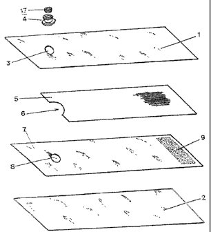
Figure 1 is a perspective, exploded, schematic view of the bag
components, spaced apart from each other, that shows their relative position.
Figure 2 is a perspective schematic view of the bag already assembled.
Figure 3 is a side schematic view, with half of it being a diameter cut,
which shows the way the bushing or nozzle component is affixed to the cover
sheet and the separating sheet the bag is comprised of. The sheets are shown
in cross section.
6
CA 02507823 2005-05-27
WO 2004/069307 PCT/EP2004/000967
Figure 4 is an elevation schematic side view of the stopper, half of which
is shown in cross section, wherein other features of the bushing shown in the
previous figure can be seen.
Figure 5 is a blown-up, cutaway partial detail of the bushing with its
complement or stopper snapped on.
Figure 6 is another blown-up partial detail of the stopper of Figure 5
corresponding to its sealing valve.
Figure 7 is a blown-up, cross section detail of the bag sealing valve.
Figure 8 is a side view of the bag for haemodialysis machines of the
present invention.
In said figures, equal reference numbers show equal or equivalent parts.
DISCLOSURE:
According to Figure 1, the bag is comprised of the following mutually
cooperating components: Two strong outer laminar layers -1- 2- of the bag,
which may consist of simple polyethylene films, mixed polyethylene and
polyesther or polyethylene and nylon laminates or any other mixed laminate
that
involves an operative improvement and a lower cost compared to using a
polyethylene-only laminate. In one of the two side layers, there is a circular
bore
- 3- around which the bushing -4- is tightly attached -S1-.
A shorter inner layer -5- is subsequently inserted, which layer is
relatively thicker, woven or injected of a thermoplastic material, adopting a
tie-
like shape, or the like, provided with a semi-circular recess - 6-, which
layer is
to be floatingly positioned between the outer sheet -1- and a third thinner
separating inner sheet -7-, which is provided with a circular orifice -8- and
a
screen-like stripe -9- at one end. This sheet is attached at the edge of the
orifice -8- to the terminal planar lip -10- of the bushing -4- by means of a
suitable welding, adhesive or the like -S2-
7
CA 02507823 2005-05-27
WO 2004/069307 PCT/EP2004/000967
Figure 2 shows the assembly, once its components have been positioned
and affixed, e.g. by welding, all around its contour -S3-.
The bushing acts as an entry nozzle for the solvent water and an exit for
the solution, which is seen in greater detail in Figure 3. It is configured as
an
annular body -4- with a discoid base of a larger diameter -11- wherein a
radial
tube is positioned -12- communicating its central axial space -13- with the
outside through said discoid base. In said inner cylindrical cavity of the
bushing
there are two projecting threads -14- and a third one -15- adjacent to the
outlet
plane which is somewhat wider than the two previous ones. On the outlet, which
has a larger diameter lip -16-, there is a small annular recess adjacent to
thread
-15-.
On this bushing -4-, a complementary member referred to as lid or
stopper -17- is snapped on, as shown in Figure 4, which lid has been designed
to effect the coupling between the bag and the outlet member provided in the
haemodialysis machine (not shown), providing the inlet of water for the
solution
and the exit of the product of the dilution.
In this complementary member there is a cylindrical central tube -18-,
which is inwardly stepwise in its mouth, defining the water inlet of the bag.
It is
surrounded by another higher cylinder -19- at the bottom of which there is at
least one radial branch -20- towards the perimeter of the member, wherein a
peripheral groove -21- is disposed. The outer contour of the member -17-,
complementary of the bushing -4- provides a larger diameter portion -22-
followed by a lesser diameter portion -23- to effect the water-tight coupling
with
the bushing -4-, in the inner cavity of which -13- it is affixed with the
functional
cooperation of the threads or ridges -24- of a larger gauge and those -25- of
a
lesser width, that are found around its contour.
8
CA 02507823 2005-05-27
WO 2004/069307 PCT/EP2004/000967
The complementary piece, which serves as a stopper once the bag has
been filled with sodium bicarbonate, is provided with a valve -26- which seals
the axial water inlet tube -18-.
Its unique structure is shown in a greater scale in Figure 7. Therein it can
be seen that it consists of a thin sheet -26- wherein some lesser strength
lines
-27- are provided in a cross-shaped configuration and ending in grooves -28-
penetrating to a depth in the order of one half of the valve disc thickness -
26-.
These grooves are disposed as a square engraved in the circular space of the
tube -18- wherein the lines of a lesser strength come to an end.
Figure 8 provides a side view of the bag, after it has been assembled and
the filling operation of chamber -A- with the sodium bicarbonate salt C to be
diluted has been completed, thus being ready to be stoppered by the second
complementary member -17-, now acting as a stopper. Adjacent to it there is
chamber -B- through which the dilution to be effected is withdrawn once it is
mounted on the machine.
OPERATION
Having thus set forth the various components of this embodiment of the
invention, and their nature disclosed, the disclosure is hereinafter
complemented by a functional and operative review of its parts and the outcome
they produce.
All of the details comprised in the invention and the way to assemble the
same are clearly established in the process. Once the bag is finished, it is
already operative to be subjected to water-tightness and strength tests, which
are carried out under at least twice the work pressure. This allows for the
verification of the quality standards of each bag and for disposing of such
units
not meeting the required -specifications without undue financial damage. Only
then are they sterilized and filled with the required amount of the product to
be
9
CA 02507823 2005-05-27
WO 2004/069307 PCT/EP2004/000967
dissolved, which in this case is Na bicarbonate. The bags are then in the
configuration shown in Figure 8, before the moment when the corresponding
lids -17- are snapped on, for which purpose the threads and recesses
machined in both pieces cooperatingly work. Inside the outlet of the
hemodialysis machine there is a conical punch that opens the valve-26 - by
tearing the lesser strength lines -27- and separating them by virtue of their
flexibility, for which the grooves -28-, acting as hinges, allow for the
motion of
the resulting triangular fragments, thus allowing for the circulation of the
solvent
water. This valve has prevented the salt from leaking, since it is originally
intact
in its closed position, and allows for the inspection for any manipulation of
the
units without any problem whatsoever.
The full bags, ready for use, already identified and labelled, are
packaged for their intended use in the aforementioned haemodialysis machines.
At the time of use, the bag is connected by its bushing and stopper in the
outlet provided by the machine, by gently pushing it in, for which purpose the
flexible but firm configuration of the complementary stopper member -17- is
useful.
After the circulation of water into the chamber -A- has been established
where the solute product is contained and isolated, the dissolution starts,
the
solution will be flowing through the filter found at the bottom of the bag,
which is
comprised of the screen-like stripe -9- and penetrating into chamber -B- from
where, circulating among the thin gaps through the woven layer -5-, it will be
withdrawn through the orifices -12- the groove -21- and tubes -20- and -19- to
enter the machine, where it will be processed at the time the concentration
reaches the anticipated value.
From the aforementioned disclosure arises the way the bicarbonate salt
has been kept intact, confined into chamber -A- of the bag, without
interfering
10i
CA 02507823 2005-05-27
WO 2004/069307 PCT/EP2004/000967
with the assembly thereof, which optimises the procedure of affixing the
bushing
and the perimetral contour of the sheets from which the bag is made, allowing
for a complete automation of the process. The way the quality testing of each
bag has been allowed before its filling and the way an automatic connection is
established with the machine using the bags, avoiding in advance the potential
fouling of chamber -B- upon the suction of the solution by the machine pump,
are illustrative of the advantage provided by the invention.
Having thus reviewed one of the possible construction leading to the
invention and the way it operates, and its specific application being further
understood, this disclosure is hereby completed by the summary of the
invention contained in the following claims.
11