Note: Descriptions are shown in the official language in which they were submitted.
CA 02507832 2005-05-30
LOAD-RECEIVING ARRANGEMENT FOR WIND TURBINE W1NGS
The present invention concerns a rotor blade of a wind power plant,
comprising a rotor blade connection for connection to a hub of the rotor of
a wind power plant and a blade tip disposed at the opposite end of the
rotor blade. Such rotor blades have generally long been known and are
used in almost all horizontal-axis wind power plants.
5.0 The invention further concerns a wind power plant having such rotor
blades.
Therefore the object of the present invention is to provide a rotor
blade in which flexing can be detected by simple means:
In a rotor blade of the kind set forth in the opening part of this
specification that object is attained in that at least one electrical
conductor
is laid over the length of the rotor blade, wherein the electrical conductor
begins at the rotor blade connection, extends in the longitudinal direction of
the rotor blade and back to the rotor blade connection, and that there is
provided a detector which detects the electrical resistance and that the
detector is connected to an evaluation device which evaluates the electrical
resistance of the conductor.
In that respect the invention is based on the realisation that flexing
of the rotor blade always leads to extension of the support structure and
that such extension, when transferred to an electrical conductor, leads to a
change in the electrical resistance of the conductor.
As that change in resistance is proportional to the extension of the
conductor, the change in resistance is proportional to the flexing of the
rotor blade. In the simplest case it is possible to predetermine a limit value
for a change in resistance, the fact of that limit value being exceeded
simultaneously indicating flexing of the rotor blade such as to cause
structural damage. Recognition of that situation therefore permits exchange
in good time or checking of the rotor blade in order to establish whether
the rotor blade has to be replaced or not.
CA 02507832 2005-05-30
2
In a preferred embodiment of the invention the loading on the wind
power plant can be inferred from the loading on the rotor blade and the
wind power plant can be shut down when a predetermined limit value is
exceeded. That reliably avoids further and also more severe loadings.
In order to be able to compensate for a temperature-dependent
change in resistance of the electrical conductor and%or to afford a plurality
of measurement results, it is possible to provide a plurality of electrical
conductors. Those conductors extend in the longitudinal direction of the
rotor blade and are connected to a detector. In that case a plurality of
conductors can be connected to a detector or each conductor can be
connected to its own detector. The conductor provided for temperature
compensation is arranged in such a way that it is not subjected to the
flexural loading and therefore only experiences a temperature-dependent
change in resistance. In that way the temperature-induced change in
resistance is known and can be suitably taken into account.
A plurality of conductors also permits redundant use. In the case of a
problem on a conductor the change in resistance can always still be reliably
detected by the redundant conductors. That eliminates the need for an
expensive overhaul operation because of the failure of a conductor.
In addition the redundant implementation of the conductors also
allows comparative ascertainment of the change in resistance. In that way
the conductors can each be monitored relative to each other by a
comparison in respect of the detected change in resistance.
In a particularly preferred feature at least one of the electrical
z5 conductors extends a predetermined distance in the longitudinal direction
of the rotor blade, that distance however being shorter than the rotor blade
length. That conductor does not reach the rotor blade tip but ends at a
predetermined Vocation on the rotor blade. In that way the individual
conductors are influenced differently in dependence on the flexing of the
rotor blade and change their resistance accordingly. Therefore the precise
pattern of the flexing effect can be inferred from the different values in
respect of the change in resistance.
CA 02507832 2005-05-30
3
In a preferred embodiment of the invention the conductors which are
shorter than the rotor blade length can also be in the form of branches of a
conductor which extends over the entire rotor blade length. For that
purpose they are galvanically connected at predetermined locations to the
conductor which extends over the rotor blade length. In that way the level
of resolution in detecting rotor blade flexing can be varied in accordance '
with the number and spacings of the branches.
In order to avoid unwanted distortion of the electrical conductors,
they are preferably connected to the support structure of the rotor blade
and in a particularly preferred feature are incorporated into the support
structure of the rotor blade. In that case, in a particularly preferred
feature,
the conductors which are to be stretched by the flexing of the rotor blade
are incorporated into the support structure. Conductors which are
galvanicalfy connected as branches to such conductors and which here
perform the function of return conductors can also be laid freely outside the
support structure, for example in the form of a cable.
In that respect it is particularly advantageous for at least one
electrical conductor to be provided in each support structure in the
longitudinal direction of the rotor blade. That arrangement also makes it
possible to detect the direction of flexing of the rotor blade as one of the
electrical conductors is subjected to a stretching effect and thus changes,
more specifically increases, its resistance, while at least one other
conductor is not stretched. Rather, with a suitable mounting configuration,
that conductor is subjected to a compression loading instead of a tension
loading and is thus upset rather than elongated. Accordingly its resistance
value changes at most in the opposite direction. It therefore decreases.
In a particularly preferred feature the electrical conductors, in
accordance with the invention, include at least one predetermined
aluminium component or comprise aluminium. That already affords a
significant change in resistance in the region of elastic deformation of the
conductor, that change in resistance being completely reversible and thus
repeatable. In a corresponding manner flexing of the rotor blade can be
permanently monitored without replacement of the electrical conductors or
CA 02507832 2005-05-30
4
even the entire rotor blade being necessary after a flexing effect has
occurred. It will be noted that in principle any electrical conductor is
suitable as a sensor. In that respect however the conductor should involve
a predetermined degree of surface roughness in order to achieve a good
mechanical join to the surrounding material.
In order not to hwe to replace the entire rotor blade in the case of a
problem in the region of the electrical conductors, for example after over-
extension or due to material flaws, the conductors are advantageously
incorporated into a member which is connected to but releasable from the
support structure. Such an embodiment of the invention also makes it
possible for rotor blades which have already been manufactured to be
retro-fitted .
The invention is described in greater detail hereinafter with reference
to the Figures in which:
Figure 1 shows a plan view of a partially sectioned rotor blade of a
first embodiment of the invention,
Figure 2 shows a plan view of a partially sectioned rotor blade of a
second embodiment of the invention,
Figure 3 shows a plan view of a partially sectioned rotor blade of a
third embodiment of the invention,
Figure 4 is a simplified side view of a rotor blade which is flexed in a
first manner,
Figure 5 is a simplified side view of a rotor blade which is flexed in a
second manner,
Figure 6 shows a simplified cross-sectional view of a rotor blade,
Figure 7 shows a further simplified cross-sectional view of a rotor
blade,
Figure 8 shows the resistance pattern of a conductor used according
to the invention,
Figure 9 shows a configuration in principle of a rotor blade according
to the invention together with measuring diagrams b) - e) in the case of an
analog phase shift,
CA 02507832 2005-05-30
Figure 10 shows a view in principle of a measuring device according
to the invention a) in the case of a rotor blade and the resulting measuring
diagrams in the case of a digital phase shift (b) - d)),
Figure il shows a view in principle of a rotor blade with a measuring
5 line,
Figure 12 shows a view as illustrated in Figure 1 i with impressed
current or voltage,
Figure 13 shows a view in principle of a rotor blade according to the
invention with a measuring line in the case of input of an input pulse and
measurement of an output pulse and a time diagram corresponding
thereto,
Figure 14 shows a switching diagram for a stopwatch process
together with time diagram, and
Figure 15 shows a circuit as illustrated in Figure 14 but for an optical
structure showing the corresponding measuring time diagram.
Figure 1 is a plan view of a rotor blade 10. To clearly illustrate the
structure the rotor blade 10 is partly sectioned so that it is possible to see
the path of two conductors 20, 22.
The rotor blade 10 is mounted with a rotor blade root 11 to the hub
12 of a wind power plant which is only indicated for orientation purposes
here and in the other Figures. A first conductor 20 and a second conductor
22 extend in the rotor blade from the rotor blade root 11 in the longitudinal
direction of the rotor blade to the rotor blade tip 13 and back again.
Accordingly each of the conductors 20, 22 includes an outgoing conductor
20a, 22a and a return conductor 20b, 22b. Both conductors 20, 22 are
connected to a detector 16 which ascertains the electrical resistance of both
conductors 20, 22.
In this case the first conductor 20 is shown as being straight. That
symbolises the fact that this conductor is connected to the rotor blade in
such a way that stretching of the rotor blade structure also leads to
stretching of that conductor 20. The second conductor 22 is shown as being
laid in a non-straight configuration in the region of the rotor blade tip 13.
That indicates that this conductor is not joined to the rotor blade 10 in such
CA 02507832 2005-05-30
6
a way that it is deformed therewith. Rather, that second conductor should
precisely not be deformed. Its resistance accordingly changes above all in
dependence on temperature so that the influence of temperature on the
change in resistance is known and can be taken into account when
detecting the change in resistance of the first electrical conductor 20, and
does not lead to false results.
The detector 16 can be connected to the control system of the wind
power plant so that flexing of the rotor blades can also be taken into
consideration in operation of the wind power plant.
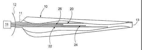
Figure 2 shows a similar structure to that which has already been
described with reference to Figure 1. It will be noted that four electrical
conductors 20, 22, 24, 26 are illustrated here. A conductor for temperature
compensation is not shown here for the sake of better clarity of the
drawing, but naturally can also be provided in this embodiment.
In this Figure all four electrical conductors 20, 22, 24, 26 are
connected to the rotor blade 10 in such a way that they follow the flexing of
the rotor blade 10. As however those conductors extend by different
distances in the longitudinal direction of the rotor blade 10, it is possible
to
infer the deformation of the rotor blade 10 from the change in resistance of
the individual conductors when their length is known.
If only the first conductor 20 which extends as far as the rotor blade
tip 13 were present, it would only be possible to infer flexing per se from
the change in resistance. As however the second conductor 22 does not
extend as far as the rotor blade tip 13, it is possible to conclude from a
change in resistance in the first conductor 20 that flexing is occurring at
the
rotor blade tip. If no changes in resistance occur in respect of the other
conductors 22, 24, 26, this meaning here and hereinafter stretch-
dependent changes in resistance, then that flexing is clearly restricted only
to the outer region of the rotor blade 10, near the rotor blade tip.
If changes in resistance occur at the conductors 20, 22 and 24 while
the resistance of the conductor 26 remains unchanged, that indicates that
the rotor blade is flexed approximately in the outer half, in the longitudinal
direction.
CA 02507832 2005-05-30
7
In this Figure the conductors 20, 22, 24, 26 are also connected to
the detector 16 which in turn can be connected to the control system for
controlling the wind power plant.
Figure 3 shows an alternative embodiment of the invention. A
conductor 20 extends in the rotor blade 10 from the detector 16 along the
entire length of the rotor blade as far as the rotor blade tip 13. Branches 28
are connected to that conductor 20 by means of a galvanic connection 29.
The choice of the number and position of the branches can predetermine
which regions of the rotor blade 10 are to be monitored, with what
accuracy. Or, to put that another way, with what level of resolution and in
what region of the rotor blade 10, flexing thereof is to be detected.
Particularly in the embodiment of the invention shown in this Figure,
it will be clear that the use of a plug connector in the region of the rotor
blade root 11 is advantageous (although not shown here) as, in production
of the rotor blade 10, the conductors 20, 28 can already be connected to
the plug connector and the connections can be tested. Upon assembly of
the rotor blade at the building site, it is then possible to use cables which
have already been made up in order to make the connection to the
detector. That provides a simple assembly procedure with a low level of
susceptibility to error.
Figure 4 is a simplified side view of a flexed rotor blade 10. This
Figure also shows the blade root region 11, the indicated hub 12 and the
detector 16. In this case the spacing of the conductors 20 relative to the
surface of the rotor blade 10 is in no way to be interpreted as being true to
scale. Rather, the situation is that detection of the degree of flexing is
more
accurate, the closer that the conductors 20 extend to the surface of the
rotor blade 10. For description purposes naturally the surface of the rotor
blade 10 and the conductors 20 are to be distinguishable in this Figure. The
rotor blade 10 is bent downwardly in this Figure. Accordingly, let the side of
the rotor blade 10 which is in the direction of flexing be the underside,
while the opposite side is accordingly the top side.
It will be clearly seen from this Figure that a conductor 20 is
provided at the top side of the rotor blade 10 and a conductor 21 is
CA 02507832 2005-05-30
provided at the underside. With the illustrated flexing of the rotor blade,
the conductor 20 at the top side of the rotor blade is stretched and involves
a significant change in its resistance so that this can be reliably detected
by
the detector 16. With this flexing of the rotor blade, the conductor 21 at the
underside of the rotor blade 10 is not stretched but is at best upset. That is
certain not to produce any increase in resistance in that conductor.
Consequently, the direction of flexing of the rotor blade can be reliably
inferred from the change in resistance in the conductor 20 at the top side of
the rotor blade 10.
Figure 5 shows a special case in terms of flexing of the rotor blade
10 which however is in no way unusual in practice. In this case, the rotor
blade is flexed in its central region in the direction of the arrow A (towards
the underside), but in its outer region near the rotor blade tip 13 it is
flexed
in the direction of the arrow B, that is to say towards the top side of the
rotor blade. Equipping the rotor blade 10 with conductors 20, 21 which both
extend as far as the rotor blade tip 13 would involve stretching for both of
those conductors.
If a fault situation is just disregarded, it is already possible to deduce
therefrom dangerous flexing of the rotor blade 10 and the plant can be
suitably controlled, for example shut down. It will be noted however that
the actual configuration involved in flexing of the rotor blade still cannot
be
recognised therefrom. As further conductors 22, 23 which do not extend to
the rotor blade tip 13 are provided, then, in the illustrated flexing
situation,
the conductor 22 is also stretched and therefore correspondingly increases
its resistance. In a corresponding manner, the actual flexing of the rotor
blade 10 can now be inferred from detection of the resistances or changes
in resistance of the conductors 20, 21, 22, 23 by the detector 16. In that
respect it should be emphasised once again that the conductors 20, 21, 22,
23 extend in very closely mutually juxtaposed relationship and as close as
possible to the respective surfaces of the rotor blade 10 so that the stretch,
which is assumed to be apparent in this Figure, of the second conductor 23
at the underside of the rotor blade does not in reality occur.
CA 02507832 2005-05-30
9
As an alternative to this embodiment with a plurality of conductors
20, 21, 22, 23 of differing lengths which here can be in the form of
conductor loops, the embodiment of the invention shown in Figure i can
naturally also be used at the top side and/or at the underside of the rotor
blade 10. That naturally also affords the advantages described therein, in
pa 'rticular the possibility of predetermining the degree of accuracy in terms
of detection of rotor blade flexing, by a choice in the number and spacing of
the branches.
Figures 6 and 7 are simplified views in cross-section through a rotor
blade according to the invention. The support structures 34, 36 extending
in the longitudinal direction are shown in the rotor blade illustrated in
Figure 6. Those support structures 34, 36 can be for example roving belts,
that is to say support structures formed from glass fibre bundles and epoxy
resin, which extend substantially over the full rotor blade length.
Electrical conductors 20, 2i, 22, 23 are embedded in those support
structures 34, 36. In that respect outgoing and return conductors are
respectively identified by the letters a and b in order to make it clear that
each arrangement involves a conductor which extends from the rotor blade
root in the longitudinal direction of the rotor blade and back again.
Incorporating the conductors 20, 21, 22, 23 into the support
structures 34, 36 means that the course thereof can be very precisely
established. That also ensures that they extend as closely as possible to the
respective surface of the rotor blade so that it is possible to draw
conclusions from the changes in resistance, with an adequate degree of
certainty.
Figure 7 also shows the support structures 34, 36. It will be noted in
this case however that the conductors 20, 21, 22, 23 are not incorporated
into the support structures 34, 36 themselves but in carriers 38. Those
carriers 38 can be of the same structure as the support structures 34, 36
so that the co-operation between the carriers 38 and the conductors 20,
21, 22, 23 exactly corresponds to the co-operation of the conductors with
the support structures 34, 36.
CA 02507832 2005-05-30
In this case the carriers 38 can be fixedly but releasably connected
to the support structures 34, 36. If replacement of a conductor should be
required due to material flaws or other damage, that does not necessarily
result in loss of the complete rotor blade or very expensive repair thereof,
5 but the corresponding carrier 38 is released from the support structure 34,
36 and replaced by a new one. '
This embodiment of the invention, with a suitable choice in respect of
the connection between the support structures 34, 36 and the carriers 38
or also the connection between the surface of the rotor blade 10 (naturally
10 at the inside) and the carriers 38, permits rotor blades which have already
been manufactured to be retro-fitted.
Figure 8 shows the empirically ascertained configuration of the
electrical resistance of a wire in dependence on the tensile stress. The left-
hand region 40 of the curve extends in a straight line, the middle region 42
of the curve rises significantly while in the right-hand region 44 the curve
initially extends in a straight line again before there is an abrupt increase
in
resistance with a subsequent reduction in resistance and finally an increase
in resistance.
The right-hand region 44 of the curve has proven to be characteristic
for the electrical conductor tearing away, at an excessively high level of
tensile stress. In contrast the change in resistance in the middle region 42
of the curve is in a range of elastic deformation of the electrical conductor.
In measurement series for ascertaining that curve, the range of elastic
deformation of the electrical conductor was ascertained at a stretch in the
longitudinal direction of less than one percent of once the conductor length
and in the case of aluminium in particular in the region of 0.3 percent.
Stretch of an aluminium wire in the longitudinal direction by 0.3
percent is accordingly elastic deformation which however results in a
significant and detectable change in resistance. That was ascertained in the
measuring series at up to 25 m~2.
As the deformation is elastic the electrical conductor is not damaged
thereby and the change in resistance is reliably reproducible. Accordingly
CA 02507832 2005-05-30
11
flexing of the rotor blade can be repeatedly detected with the same
electrical conductors.
Further Figures 9 and 10 respectively show an addition to and an
alternative to the above-described process or above-disclosed approach.
That approach can be implemented with analog and/or digital signals. What
is common to both solutions as shown in Figures 9 and 10 is that the delay
time of the signals in the circuit is not involved in the delay time detection
procedure. In that way it is possible to ascertain the actual delay time in
the line.
The structure of the analog and digital solutions in Figures 9 and 10
is substantially comparable. In both cases, between the transmitter and the
receiver there are two lines, namely a reference line whose length does not
change and in parallel therewith a measuring line, by way of the stretch of
which the flexing for example of a rotor blade is detected. Besides the fact
that here the delay times can be compared between the reference line and
the measuring line, those two lines are also subject to the same thermal
influences so that the effect thereof is compensated.
In the analog arrangement (first alternative), in the rest condition
the reference signal (an analog electrical signal) and the measuring signal
are in-phase. Accordingly there is a sum signal of the same frequency but
higher amplitude.
If a phase shift occurs due to stretching of the measuring line the
sum signal is naturally also changed. On the one hand the peak-to-peak
value is less than in the case of in-phase signals, while in addition there is
also a modified envelope curve for the sum signal.
The way in which such changes are detected is sufficiently known in
the state of the art. It can be readily seen that the amplitude becomes less,
up to a phase shift of 180°. Beyond that range, up to a complete
period,
the signs also have to be taken into consideration in order to obtain reliable
information regarding the phase position.
In the case of the digital solution, with in-phase input of the signals
at the receiver, the arrangement involves the lowest arithmetic mean
(naturally also in dependence on the pulse duty factor). Assuming a pulse
CA 02507832 2005-05-30
12
duty factor which is still the same however, the arithmetic mean increases
with increasing phase shift between the reference signal and the
measurement signal. That is therefore a measurement in respect of the
phase shift of the signals at the receiver.
The above-described processes can be implemented with electrical
signals, optical signals and basically also acoustic signals. Basically the
situation is such that, with a slight amount of stretch, the choice of a high
frequency is advantageous (that is to say a frequency of more than ikHz,
preferably several MHz), while in the case of a large amount of stretch, the
choice of a low frequency is to be preferred in order to obtain a respective
phase shift in the range within one period.
The present application expressly incorporates the content of
German patent applications Nos 38 21 642 and 37 12 780. It is known from
those applications how changes in length or spacing, which are caused by a
change in physical parameters such as temperature or pressure, can be
determined by means of delay time measurement of electrical signals in an
optical fibre cable which is exposed to the physical parameter. Signals are
fed into the optical fibre cable by way of an optical multivibrator. In that
situation, the total delay of a plurality of pulses is determined by way of a
high-frequency counter. By comparison with a standard counting result
(reference), the deviation of the actually ascertained counting result from
that standard counting result is established, the difference in length or
spacing occurring is ascertained therefrom, and that difference in length or
spacing is converted into the physical parameter to be determined.
DE 37 12 780 discloses a process and an apparatus for precise and
fast measurement of the length of a line to be tested as far as an electrical
discontinuity in the line, wherein a pulse edge is passed by a pulse edge
generator to an end of the line, the reflected pulse edge which returns from
the discontinuity to the one end is detected, the production of a pulse edge
is triggered after a predetermined time after detection of the reflected
pulse edge so that the pulse edge generator is caused to repeatedly
produce the pulse edge at a frequency which is related to the transit time
delay in the length of the line, and that frequency is measured. DE 37 12
CA 02507832 2005-05-30
13
780 thus describes how a 'discontinuity' in the line can be detected and also
discloses the possibility, instead of using the delay time, of using the
inverse, that is to say more specifically the frequency.
In accordance with DE 38 21 642, the delay time in a line between a
transmitter and a receiver is detected, and that is effected by means of the
so-called stopwatch process, that is to say, the counting of clocks of a
signal at a markedly higher frequency begins with the emission of a pulse
and that counting procedure is continued until the receiver receives the
pulse. The count value is then a measurement in respect of the delay time.
i0 Reference is now made to Figure 11 which (as has already been done
in Figures 9 and 10) basically shows a rotor blade with a measuring line
which is arranged therein and which is preferably let in the surface of the
rotor blade in the form of a measuring wire (or optical fibre cable or OFC).
Mechanical loads (wind loads) flex the rotor blade and the measuring line is
i5 stretched or upset in its length. That change in load is therefore
proportional to the change in length:
of N DI.
A change in length of between 0.0% and 0.2% is to be expected,
which corresponds to between 0.0% and 100% load. The task therefore is
20 to determine the change in length with the highest possible level of
resolution.
As a first solution, the ohmic resistance of the wire can be assumed
to be proportional to the length and thus also to the load.
0R N 01 N OF.
25 A current is impressed into the wire and the voltage drop is
measured by way thereof, as is shown in Figure 2.
Tests have shown that this principle is operable.
There are however some problems because a very high level of
measuring accuracy is required (c 0.002%) as the signal is 0.2% of the
30 absolute value and also has to be subdivided into at least 100 steps. In
addition the ohmic resistance of the wire changes very severely with the
wire temperature. Superimposed on the signal are noises which can be
produced by electrical and magnetic fields. That becomes particularly
CA 02507832 2005-05-30
14
noticeable when thunderstorms occur. The wire with the electronics
connected thereto can be damaged by direct lightning hits.
An alternative solution is shown in Figure 13. In this case the length
of the transit wire is determined by the delay time of a pulse. The speed is
2/3rds light speed, that is to say about 200,000 km/s.
As can be seen from Figure 13:
~t N L1I N ~F
and the change in transit time is a measurement of the load.
With an assumed line length of 40 m this gives t = 200 ns with a
superimposition of of of between 0 and 400 ps.
As that time is not so easy to detect by a measurement procedure,
the inverse is formed, more specifically as:
f- 1
t+Ot
That now affords a frequency.
Frequency values are very simple to determine and the
measurement value can be resolved as finely as may be desired (by
adaptation of the gate time of the frequency counter).
A frequency is now formed from the delay time of the signal by a
procedure whereby the incoming pulse immediately sends a fresh pulse into
the line (stopwatch process). The number of pulses emitted per second
forms the frequency.
Figure 14 shows a corresponding circuit diagram in that respect
together with a time diagram.
The pulse is replaced by a change in level and, as expected, there is
a frequency of:
f = 2t , that is to say with t = 2
2~ 3 CJ
With a line length of 40 m that gives:
40m
f 2(200 ~ 10-9m/ s + Ot) 2~5MHz
CA 02507832 2005-05-30
Due to the effect of load, there are frequencies of between 2.5 MHz
and 2.505 MHz, that is to say a change in value of 5000 Hz.
A frequency counter with a gate time of 20 ms would deliver 50
values per second with a resolution in respect of the load of i%. Those
5 values then already comprise mean values of 50 individual length
measurements.
There is therefore then the advantage that no sensitive analog
sensor system is required as there is a high signal-to-noise ratio (OV or
lOV) and there are no troublesome delay time changes due to temperature
10 fluctuations.
That applies in particular in accordance with the arrangement shown
in Figures 9 and 10 where, besides the measuring line, there is also a
reference line.
The above-described solution can also be implemented optically. In
15 that case a wire is replaced by an optical fibre cable and the feedback is
effected by an OFC transmitter and an OFC receiver, as is shown in Figure
i5.
In this case the advantages are in particular that there is no need for
a sensitive analog sensor system as there is a high signal-to-noise ratio
(light on or off), there are no troublesome delay time changes due to
temperature fluctuations, there is no noise disturbance on the optical fibre
cable due to electrical or magnetic fields and no effects due to a lightning
strike are also to be expected.
It is to be expected that in practice flexing of the blade is already to
be clearly measured with a change in length of less than 1 mm. Insofar as
the present application describes that the solution according to the
invention is to be used in relation to a change in length of the rotor blade,
it
is to be noted that it is also possible to measure twisting of the rotor blade
if the measuring line is correspondingly arranged in a spiral shape on the
surface of the rotor blade so that twisting of the rotor blade also
automatically leads to a change in length of the wound-on measuring line.
In particular the measuring method according to the invention can
also be used for monitoring by a measuring procedure portions of the rotor
CA 02507832 2005-05-30
16
blade in respect of their loading and also lengthwise stretching, which can
be very helpful in particular in the blade tip region when gusts occur in
order to detect better than hitherto the risks involved in a specific
individual
case of given blade loads.
It should be expressly pointed out that what is disclosed in Figures
11 to 14 can obviously also be readily combined with what is disclosed in
the other Figures. When reference is made to a stopwatch process, it is
hereby made clear that this means inter alia that the stopwatch is stopped
upon reception of the emitted pulse and started again at the same time,
and accordingly signifies the frequency of the stop/start cycles on a given
time range, for example i second.
In that respect it is possible to envisage any form of a pulse signal,
inter alia also a chirp pulse signal, in accordance with the sine x/x
function.