Note: Descriptions are shown in the official language in which they were submitted.
CA 02508260 2005-06-O1
WO 2004/055956 PCT/US2003/039145
A STATOR ASSEMBLY WITH AN OVERMOLDING THAT SECURES
MAGNETS TO A FLUX RING AND THE FLUX RING TO A STATOR HOUSING
CROSS-REFERENCE TO RELATED APPLICATIONS
[0001] This application is a continuation-in-part of U.S. Patent
Application No. 10/468,643 filed August 20, 2003, which is a ~ 371 National
Phase filing of PCT International Application PCT/US02/05029 filed February
22,
2002 (International Publication Number WO 02/068235 A2) which claims the
benefit of U.S. Provisional Application No. 60/271,141 filed February 23,
2001.
This application claims the benefit of U.S. Provisional Application No.
60/433,496
filed December 13, 2002. The disclosures of the above applications are
incorporated herein by reference.
FIELD OF THE INVENTION
[0002] The present invention relates to electric motors, and more
particularly to stator assemblies for electric motors.
BACKGROUND OF THE INVENTION
[0003] In the construction of stator assemblies for permanent magnet
electric motors, magnets are retained within the stator assembly. For example,
in a brush-type permanent magnet electric motor, magnets are retained on a
stator housing or a separate flux ring within the stator housing. This
generally
requires gluing or adhering each individual magnet to the flux ring or stator
housing.
[0004] Various types of adhesives have been used to adhere the
magnets to the metallic surface. It is possible that a sudden shock to the
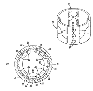
electric
motor will destroy the bond between the magnet and the flux ring or stator
housing. This would result in movement of the magnet within the stator
assembly. The magnet itself could even break. As a result, the electric motor
ceases to properly function.
[0005] It is known in the art to provide an anchor in the flux ring or
stator housing. Magnetic material is then injection molded on the flux ring or
1
CA 02508260 2005-06-O1
WO 2004/055956 PCT/US2003/039145
stator housing and is retained in position by the anchor. Such an anchor
system
is disclosed in U.S. Patent No. 6,522,042 issued February 18, 2003 entitled
Anchoring System for Injection Molded Magnets on a Flux Ring or Motor
Housing and in U.S. Application Serial No. 09/764,004 filed January 17, 2001
entitled Anchoring System for Injection Molded Magnets on a Flux Ring or Motor
Housing. However, a disadvantage of the anchoring systems described in the
above-identified patent applications is that they require the use of injection
molded magnetic material. This is typically the most expensive type of
magnetic
material per unit flux.
SUMMARY OF THE INVENTION
[0006] Accordingly, the present invention provides a stator assembly
for an electric motor. The stator assembly includes a stator housing, a split
flux
ring inserted into the stator housing and a plurality of magnets on an inner
surface of the flux ring. An overmolding secures the magnets to the flux ring
and
asserts a radial force on the flux ring to secure it to the stator housing.
Additionally, the overmolding fills the seam of the flux ring and prevents
collapse
of the flux ring.
[0007] In an aspect of the invention, the material used to mold the
overmolding is a plastic that is injection molded about the magnets on the
flux
ring after the flux ring and magnets have been placed in the stator housing.
The
pressure of the plastic as it is being injection molded exerts a radial
pressure on
the flux ring, expanding it against the stator housing and secures it to the
stator
housing. The overmolding also secures the magnets to the flux ring.
[0008] In an aspect of the invention, the flux ring is aligned with the
stator housing and is further secured to it by engagement of a dimple in one
of
the flux ring and stator housing with a hole in the other of the flux ring and
the
stator housing.
[0009] In an aspect of the invention, at least one of a rear bearing
support, front bearing support and fan baffle are integrally molded with the
overmolding when the material used to mold the overmolding is molded.
2
CA 02508260 2005-06-O1
WO 2004/055956 PCT/US2003/039145
[0010] In an aspect of the invention, the overmolding is formed with
slots of different widths between magnetic poles of the stator assembly to
provide a keying feature for the stator assembly to key it, such as when it is
placed in a magnetizer.
[0011] In an aspect of the invention, the flux ring and housing are
preformed as a unit by stamping them from blanks and rolling them together. In
a variation, the flux ring blank is rolled first to form the flux ring and the
housing
blank rolled around the flux ring with the flux ring acting as a rolling
arbor.
[0012] In an aspect of the invention, an electric motor has an armature
and a stator assembly in accordance with the invention.
[0013] In an aspect of the invention, a power tool has a housing
including an electric motor having an output coupled to a transmission. The
electric motor has an armature and a stator assembly in accordance with the
invention.
[0014] Further areas of applicability of the present invention will
become apparent from the detailed description provided hereinafter. It should
be
understood that the detailed description and specific examples, while
indicating
the preferred embodiment of the invention, are intended for purposes of
illustration only and are not intended to limit the scope of the invention.
BRIEF DESCRIPTION OF THE DRAWINGS
[0015] The present invention will become more fully understood from
the detailed description and the accompanying drawings, wherein:
[0016] Figure 1 is a cross-sectional view of a power tool according to
the present invention;
[0017] Figure 2 is a perspective view of a stator assembly of the power
tool of Figure 1;
[0018] Fig. 3 is a cross-section view of the stator assembly of Fig. 2
taken along the line 3 - 3;
[0019] Fig. 4 is a perspective view of a flux ring of the stator assembly
of Fig. 2;
3
CA 02508260 2005-06-O1
WO 2004/055956 PCT/US2003/039145
[0020] Fig. 5 is a perspective view of a stator can or housing of the
stator assembly of Fig. 2;
[0021] Fig. 6 is a perspective view of the flux ring of Fig. 4 received in
the stator can of Fig. 5;
[0022] Fig. 7 is a perspective view of a variation of the flux ring of Fig.
4 showing a flux ring with interlocking fingers;
[0023] Fig. 8 is a cross-sectional view of an alternative configuration of
the stator assembly of Fig. 2;
[0024] Fig. 9 is a perspective view of an electric motor having an
alternative configuration of the stator assembly of Fig. 2;
[0025] Fig. 10 is a cross-sectional view of the electric motor of Fig. 9
taken along the line 10 - 10;
[0026] Fig. 11 is a perspective view of an alternative stator assembly;
and
[0027] Fig. 12 is a perspective view of still another alternative stator
assembly.
DETAILED DESCRIPTION OF THE PREFERRED EMBODIMENTS
[0028] The following description of the preferred embodiments is
merely exemplary in nature and is in no way intended to limit the invention,
its
application, or uses.
[0029] Referring now to Figure 1, a power tool 10 is shown. The
power tool 10 is illustrated as a drill, however, any type of power tool may
be
used in accordance with the present invention. The power tool 10 includes a
housing 12 which surrounds a motor 14. An activation member 16 is coupled
with the motor and a power source 18. The power source 18 includes either a
power cord (AC current) or includes a battery (DC current) (not shown). The
motor 14 is coupled with an output 20 that includes a transmission 22 and a
chuck 24. The chuck 24 is operable to retain a tool (not shown).
[0030] The motor includes a stator assembly 30. The stator assembly
30 includes a stator housing 32, a flux ring 34 and magnets 36. The flux ring
34
is an expandable or split flux ring. An armature 40 includes a shaft 42, a
rotor 44
4
CA 02508260 2005-06-O1
WO 2004/055956 PCT/US2003/039145
and a commutator 50 coupled with the shaft 42. The rotor 44 includes
laminations 46 and windings 48. The motor 14 also includes end plates 52 and
54. End plate 52 includes a front bearing 56 which supports one end of a shaft
42. The shaft 42 is coupled with a pinion 60 that is part of the output 20.
Brushes 62 and 64 are associated with the commutator 50. A rear bearing 70 is
also coupled with the end plate 54 to balance rotation of the shaft 42.
[0031] Referring now to Figs. 2 - 6, the stator assembly 30 is
described in further detail. Stator housing 32 and flux ring 34 are
illustratively
made of soft magnetic material, such as cold rolled steel. The flux ring 34
has
anchors 80 extending radially inward. The magnets 36 are disposed around an
inner surface 82 of the flux ring 34 between anchors 80. An overmolding 84
secures the magnets 36 to flux ring 34 as described in more detail in WO
02/068235 A2.
[0032] The flux ring 34 is discontinuous having a seam 86 extending
therealong. The seam 86 enables the flux ring 34 to be compressed for
insertion
into the stator housing 32. When flux ring 34 is assembled in stator assembly
30, the seam 86 is preferably disposed over one of magnetic poles P~, P2 of
the
stator assembly 30 to minimize magnetic losses. In the configuration of Figs.
2
6, the flux ring 34 includes a projection or dimple 88 that engages a hole 90
in
the stator housing 32. Alternatively, as shown in Fig. 8, the stator housing
32
includes a projection or dimple 92 that engages a hole 94 in the flux ring 34.
Engagement of the dimple 88,92 and hole 90,94 provides proper alignment of
the flux ring 34 during assembly of the stator assembly 30. The dimple 88,92
and hole 90,94 are illustratively at ninety degrees to seam 86 to provide
sufficient displacement of dimple 88 or hole 94, as applicable, in flux ring
34 with
respect to stator housing 32 when flux ring 34 is compressed so that when flux
ring 34 is uncompressed, dimple 88 will be urged into hole 90 (or hole 94
around
dimple 92). Alternatively, the dimple 88, 92 and hole 90, 94 are ideally
centered
over one of the magnetic poles P~, P2 to reduce magnetic losses. Overmolding
84 is formed so there are slots 95, 96 on diametrically opposite sides of flux
ring
34 between the overmolding 84 around magnets 36 of pole P~, and the
overmolding 84 around magnets 36 of pole P2, Slots 95, 96 illustratively
extend
5
CA 02508260 2005-06-O1
WO 2004/055956 PCT/US2003/039145
axially along inner surface 82 of flux ring 34 between poles P~ and P2. Slots
95,
96 may be gaps in the overmolding 84 or regions of reduced thickness in the
overmolding 84. In the illustrative embodiment, stator assembly 30 has one
pair
of magnetic poles, with one of poles P~ and P2 thus being a North pole and the
other being a South pole. It should be understood that stator assembly 30
could
have more than one pair of North and South poles.
[0033] To assemble the stator assembly 30, stator housing 32 and flux
ring 34 are each preformed. In this regard, stator housing 32 illustratively
has
interlocking fingers 33 as shown in Fig. 5. The flux ring 34 is slightly
compressed and inserted into the stator housing 32 as shown in Fig. 6. The
dimple 88,92 engages the hole 90,94 as described above. The magnets 36 are
placed against the inner surface 82 of the flux ring 34 and are positioned
between the anchors 80. The magnets 36 can be lightly magnetized so they are
retained against the inner surface 82 of flux ring 34 during assembly.
[0034] Overmold material 83, such as plastic, is injection molded into
the stator assembly 30 to form the overmolding 84. During the injection
molding
process, the pressure of the overmold material 83 pushes against the magnets
36 and flux ring 34, expanding the flux ring 34 against the stator housing 32.
The overmold material 83 fills the seam 86 of flux ring 34 and surrounds the
magnets 36. Expansion of the flux ring 34 against the stator housing 32
provides the retention force for retaining the flux ring 34 within the stator
housing
32. Further, because the overmolding 84 fills the seam 86 of the flux ring 34,
compression of the flux ring 34 in the stator housing 32 is prevented after
the
overmold material 83 hardens, thus preventing the removal of flux ring 34 from
the stator housing 32. The engagement of the dimple 88, 92 and hole 90, 94,
held in place by the overmolding 84, further secures the flux ring 34 to the
stator
housing 32. The diameter and true position of the overmolding 84 are
maintained closely relative to the inside diameter of the stator housing 32 to
reduce tolerance stack-ups to the armature 40 (Fig. 1 ). It should be
understood
that there can be more than one dimple/hole arrangement in flux ring 34 and
stator housing 32.
6
CA 02508260 2005-06-O1
WO 2004/055956 PCT/US2003/039145
[0035] In an aspect of the invention, slot 95 is wider than slot 96. This
limits to two the orientations in which stator assembly 30 can be placed in a
magnetizer (not shown) used to magnetize magnets 36 after stator assembly 30
is assembled. That is, the difference in the widths of slots 95 and 96 provide
a
keying feature that keys stator assembly 30 to the magnetizer. If the widths
of
slot 95 and 96 were the same, stator assembly 30 could be placed in the
magnetizer in four orientations. That is, either end of stator assembly 30
could
be placed in the magnetizer in two orientations that are 180 degrees apart. By
forming the keying feature in the overmolding 84, each end of the stator
assembly 30 can be placed in the magnetizer in only one orientation, reducing
to
two the orientations in which the stator assembly 30 can be placed in the
magnetizer. This makes sensing of the stator assembly 30 in the magnetizer
fixture more robust and eliminates the possibility of magnetizing backwards
due
to placing the stator assembly 30 in the magnetizer in the wrong orientation.
It
should be understood that in stator assemblies having more than two poles,
preferably the width of only one of the slots between the poles would be
different
than the widths of the rest of the slots between the poles to key the stator
assembly to the magnetizer.
[0036] In an aspect of the invention, the stator housing 32 and the flux
ring 34 are preassembled as a unit according to an alternative assembly
method.
More specifically, the stator housing 32 and flux ring 34 are formed of
separate
blanks, such as steel blanks, and in this regard, the edges of the seams of
flux
ring 34 and stator housing 32 are formed to have interlocking fingers, such as
interlocking fingers 33 shown in Fig. 5 for stator housing 32 and interlocking
fingers 37 shown in Fig. 7 for flux ring 34. One or more holes 94 are stamped
into the flux ring and matching mating dimples) 92 stamped in the stator
housing
32, or vice-versa. The stator housing 32 and flux ring 34 are lain together in
their
flat, pre-rolled states with the holes and dimples engaged. The stator housing
32
and flux ring 34 are rolled and the seam of the flux ring 34 interlocks as
does the
seam of the stator housing 32. The holes and dimples maintain alignment of the
stator housing 32 and flux ring 34 during the rolling process.
7
CA 02508260 2005-06-O1
WO 2004/055956 PCT/US2003/039145
[0037] In an alternative, the flux ring 34 can be rolled first and the
stator housing 32 rolled about the flux ring 34. In this case, the flux ring
34 acts
as a rolling arbor. Additionally, the holes and dimples maintain alignment as
the
stator housing 32 is rolled about the flux ring 34. According to another
alternative, the stator housing 32 and flux ring 34 can be spot-welded
together to
form a sub-assembly. Regardless of how the stator housing 32 and flux ring 34
are assembled together, injection of the overmold material 83 not only secures
the magnets 36 to the flux ring 34 but also secures the flux ring 34 to the
stator
housing 32 through the pressure exerted on the flux ring 34 therein.
[0038] The stator assembly 30 of the present invention provides
significant advantages in both assembly and manufacture of the power tool 10.
In particular, the stator assembly 30 eliminates the need for welding
equipment
to secure the components together. The expansion of flux ring 34 against
stator
housing 32 induced by injection of the overmold material 83 secures the flux
ring
34 to stator housing 32 and the overmolding 84 also secures the magnets to
flux
ring 34. The interlocking of the dimple/hole arrangements) further secure the
flux ring 34 to the stator housing 32. Further, injection of the overmold
material
83 reduces tolerance stack-ups, improving ease of assembly. As a result,
manufacturing equipment and floor space is reduced entailing cost savings.
Another advantage of reduced tolerance stack-ups is that the magnet can be
placed closer to the armature 40 thus maximizing motor performance. The
keying feature provided by the different widths of slots 95, 96 improve the
placement of stator assembly 30 in the magnetizer.
[0039] Turning now to Figs. 9 and 10, an electric motor 98 having a
further embodiment of the stator assembly 30, indicated generally by reference
numeral 100, is shown. The stator assembly 100 includes the stator housing 32,
flux ring 34, and permanent magnets 36 as shown in the stator assembly 30 of
Figs. 2 - 6. The stator assembly 100 further includes an integrally molded
commutator end or rear bearing support 102 and an integrally molded fan baffle
104. An armature, such as armature 40 (Fig. 1 ), is received in stator
assembly
100. A fan 112 is affixed at one end of shaft 42 of armature 40 and is
disposed
within fan baffle 104. An insulative sleeve 114 may illustratively be disposed
8
CA 02508260 2005-06-O1
WO 2004/055956 PCT/US2003/039145
between shaft 42 and laminations 46 and between shaft 42 and commutator 50.
An end plate (not shown in Figs. 9 and 10), such as end plate 52 (Fig. 1 ), is
affixed to fan baffle 104.
[0040] The rear bearing support 102 includes a cap 106 integrally
molded from the overmold material 83. The cap 106 includes a pocket 108 for
receiving rear bearing 70 (Fig. 1 ). Integrally forming the cap 106 as part of
the
overmolding 84 from the overmold material 83 eliminates the need for separate
fasteners to fix the rear bearing support 102 to the stator housing 32. The
fan
baffle 104 is likewise integrally molded from the overmold material 83.
[0041] Turning now to Fig. 11, an alternate embodiment of stator
assembly 100 is shown and generally indicated by reference numeral 100'.
Stator assembly 100' is substantially similar to the stator assembly 100 shown
in
Figs. 9 and 10, however, only the rear bearing support 102 is integrally
molded
as part of the overmolding 84 from the overmold material 83. Alternatively, a
front bearing support 103 (shown in phantom in Fig. 11 ) for engaging a front
bearing, such as bearing 56 (Fig. 1 ), may be integrally molded in a manner
substantially similar to the rear bearing support 102.
[0042] With reference to Fig. 12, another alternate embodiment of
stator assembly 100 is illustrated and generally indicated by reference
numeral
100". Stator assembly 100" is substantially similar to the stator assembly 100
shown in Figs. 9 and 10, however, only the fan baffle 104 is integrally molded
as
part of overmolding 84 from the overmold material 83.
[0043] By integrally molding the commutator end bearing support 102
and the fan baffle 104 as part of overmolding 84, further assembly and costs
savings may be realized.
[0044] The description of the invention is merely exemplary in nature
and, thus, variations that do not depart from the gist of the invention are
intended
to be within the scope of the invention. Such variations are not to be
regarded
as a departure from the spirit and scope of the invention.
9