Note: Descriptions are shown in the official language in which they were submitted.
CA 02508277 2005-05-25
AGRICULTURAL SILO AUGER SYSTEM APPARATUS AND METHOD
FIELD OF THE INVENTION
The present invention relates to a multiple auger method and apparatus and
S method for transporting and redistributing silage within a silo.
BACKGROUND OF THE INVENTION
Systems for transporting and redistributing silage within a silo typically
include
an auger assembly extending horizontally from the center of the silo to the
inner wall of
the silo. As silage is directed into the center of the silo during the loading
process, axial
rotation of the individual augers) transports the silage outward from the
center of the
silo toward the wall of the silo. The auger assembly also rotates about the
center of the
silo and "sweeps" an essentially horizontal cross section of the silo in a
clock hand-type
manner. The combination of the rotation of the individual augers) and the
sweeping
1 S action of the auger assembly moves the silage radially outward and ensures
that the
silage filling the silo is evenly distributed across a cross section of the
silo.
The auger systems also work during the silo unloading process. The direction
of
rotation of the individual augers) is reversed so that silage is moved
radially inwardly
from the outer areas of the silo toward the silo center. During the unloading
process, the
auger assembly is also moved in a sweeping action as described above. Through
the
rotary action of the individual augers) and the sweeping movement of the auger
assembly, silage is transported radially inward from the outer areas of the
silo to a hole
CA 02508277 2005-05-25
in the center of the stored silage. The transported silage is then directed
downwardly
through the center hole and down to a conveyor belt or discharge apparatus at
the base
of the silo. The discharge apparatus discharges the silage from the silo.
The prior art includes auger assemblies having single and double auger
configurations. The single auger configuration is the simplest and it allows
an operator
to go from a silo loading configuration to an unloading configuration by
simply flipping
a switch to reverse the direction of auger rotation. However, a single auger
system
requires the use of a relatively large diameter auger. To be effective, the
large diameter
auger must be rotated relatively slowly and functions by moving the
transported silage
underneath the auger. Although the single auger configuration has important
advantages, it is also relatively slow and inefficient.
Conventional dual auger assemblies allow the use of smaller diameter augers
that can be rotated at an increased speed relative to the single auger
configuration. In a
dual auger assembly, the two augers have opposite flighting and rotate in
opposite
directions. Silage is lifted upwardly by rotation of the augers and carried in
the
direction dictated by the auger flighting. While a conventional dual auger
system is
faster and more efficient than a single auger system, the dual auger system
cannot be
easily changed from a loading to an unloading configuration. Changing a
conventional
dual auger configuration from a loading to an unloading configuration requires
an
operator to physically enter the silo and manually reverse the positions of
the augers.
2
CA 02508277 2005-05-25
The process of reversing the augers involves manually manipulating heavy
machinery
and is inconvenient, time consuming, and difficult.
The need exists for an auger assembly that can transport silage quickly and
efficiently while having the ability to go from a loading configuration to an
unloading
configuration without going through an arduous reversal process. The present
invention
provides a three-auger system that transports silage more quickly than a dual
auger
system, while also having the advantage of allowing an operator to switch from
a
loading configuration to an unloading configuration by simply flipping a
switch.
SUMMARY OF THE INVENTION
The present invention is an auger assembly used to transport silage within a
silo
during the loading and unloading processes. The assembly is comprised of three
individual augers that cooperate to transport silage within the silo. The
first and third or
outer augers have the same flighting and rotate in the same direction. The
second auger
or inner auger is positioned between the first and third augers and rotates in
the opposite
direction and has flighting that is the opposite of the flighting of the first
and third
augers. The individual augers rotate so that silage is moved parallel to the
longitudinal
axes of the augers. The auger assembly also sweeps an essentially horizontal
cross
section of the silo. During a loading operation, silage is moved outwardly
from center
of the silo toward the inner wall of the silo. During an unloading operation,
silage is
moved inwardly to a discharge assembly in communication with a hole in the
center of
CA 02508277 2005-05-25
the stored silage. The auger assembly allows the assembly to transition from a
loading to
an unloading configuration by simply electronically reversing the direction of
rotation of
the individual augers without mechanically altering the auger assembly
configuration.
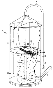
BRIEF DESCRIPTION OF THE DRAWIrIGS
Figure 1 is a perspective view with portions of the silo broken away showing
the
auger assembly of the present invention suspended within the silo.
Figure 2 is a fragmentary top plan view of Figure 1.
Figure 3 is a fragmentary elevational view taken along the line 3-3 in Figure
2 and
viewed in the direction of the arrows.
Figure 4 is a fragmentary top plan view of Figure 1 showing the diverter
assembly.
Figure 5 is an elevational view of the auger assembly as viewed from the
center of
the silo during a silo-loading (filling) operation.
Figure 6 is an elevational view of the auger assembly as viewed from the
center of
a silo during a silo-unloading operation.
Figure 7 is an elevational view of an alternative embodiment comprising two
augers and two associated banking boards.
DETAILED DESCRIPTION OF PREFERRED EMBODIMENTS
Figure 1 illustrates the auger assembly A of the present invention suspended
within a silo, preferably a top-loading silo S. The auger assembly A generally
includes
4
CA 02508277 2005-05-25
a plurality of individual augers, preferably three augers, supported within a
frame
assembly F. A support cable system extends along the exterior of the silo S
upwardly
through a suspensions system and down into the silo S. The suspension system
is
comprised of pulleys and cable manipulation and support mechanisms that direct
support cables downwardly toward the auger assembly A. The suspension system
and
the support cable systems are both well known in the art. Support cables
attach to a
stem assembly 10 to support a first end 8 of the auger assembly A. Support
cables also
attach to a ring assembly 12, which supports a second end 14 of the auger
assembly A.
A spider frame assembly 20 maintains the stem assembly 10 centered within the
silo S.
During silo loading and unloading operations, a winch 18 positioned on the
exterior of the silo S cooperates with the cable support system and raises and
lowers the
auger assembly A. During loading operations, a diverter assembly 22, as best
shown in
Fig. 4, directs incoming silage to an area between two of the three augers.
Upper auger support system 23, as best shown in Figures 2 and 3, includes at
least two elongate members 24 that extend from the first end 8 of the auger
assembly A
to the second end 14 of the auger assembly A. Multiple upper cross members 26
extend
across and are secured to the elongated members 24. The cross members include
at
least an inner cross member 27, an outer cross member 31, and a centerline
cross
member 33. The centerline cross member 33 extends across the elongated members
24
in the approximate area where the silo centerline intersects the auger
assembly A when
CA 02508277 2005-05-25
the auger assembly A is in the normal operating position, as best shown in
Figure 1.
The elongated members 24 and the cross members 26, 27, 31, and 33 form the
upper
auger support system 23.
Lower auger support carnage 35, as best shown in Figures 2 and 3, extends
below the upper auger support system 23. The lower auger support carriage 35
is
comprised of at least a gearing support member 29 at the first end 8 of the
auger
assembly A, and an outer auger support member 46 at the second end 14 of the
auger
assembly A. The outer auger support member 46 is positioned beneath the outer
support cross member 31. The combination of the lower auger support carriage
35 and
the upper auger support system 23 comprises the frame assembly F.
The auger assembly A includes first 28, second 30, and third 32 individual
augers as best shown in Figures 2, 3, 5, and 6. The first 28 and third 32
augers have the
same flighting. The second auger 30 has flighting that is different from the
first 28 and
third 32 augers, preferably opposite of the first 28 and third 32 augers. In
the preferred
embodiment, the first 28 and third 32 augers have le$-hand flighting and the
second
auger 30 has right-hand flighting. In the preferred embodiment, the augers 28,
30, 32
are equally spaced, extend parallel to one another on the same horizontal
plane, and
rotate on parallel axes.
Alternative auger configurations should be considered within the scope of the
6
CA 02508277 2005-05-25
invention. The relative diameters, spacing, and length of the first 28, second
30, and
third 32 augers may be modified. For example, the second auger 30 may be
modified to
have a significantly larger diameter than the first 28 and third 32 augers to
enhance the
effect of the second auger 30 relative to the first 28 and third 32 augers.
Similarly, the
augers need not be disposed on the same plane, or they may be disposed along a
non-
horizontal plane.
A first reversible motor 36, as best shown in Fig. 2, preferably positioned on
the
inner cross member 27, powers first 38, second 40, and third 42 gearboxes,
preferably
positioned on the gearing member 29. A speed reducer 21 transfers power from
the first
reversible motor 36 to a power transmission shaft within the gearing support
member
29. The power transmission shaft transfers power to the first 38, second 40,
and third
42 gearboxes. The first 38 and third 42 gearboxes are right-angle gearboxes,
and the
second gear box 40 is a three-way gearbox. The first 38, second 40, and third
42
gearboxes then power the first 28, second 30, and third 32 augers
respectively.
Alternate gearing and power transmission arrangements should be considered
within the scope of the invention. For example, in an alternative embodiment,
an
optional clutch assembly 37 prevents the first reversible motor 36 from
powering the
third gearbox 42 and the third auger 32 during unloading operations, so that
all available
power is directed to the first 28 and second 30 augers. Additionally, multiple
motors
may drive the gear boxes 38, 40, 42, or the gearboxes 38, 40, 42 may be
combined into
CA 02508277 2005-05-25
one or two gearing assemblies.
As best shown in Figures 2 and 3, the second end 14 of the auger assembly A is
rotatably connected to a stationary ring assembly 12 through a gearing
mechanism 56,
58. A second reversible motor 54 is preferably positioned on the outer cross
member 31
to provide power to the gearing mechanism 56, 58 at the second end 14 of the
auger
assembly A. Specifically, the second reversible motor 54 powers a perimeter
gearing
assembly 56 that meshes with a gear track 58 on the ring assembly 12. The
auger
assembly A pivots as the perimeter gearing assembly 56 moves about the gear
track 58
on the ring assembly 12. The ring assembly 12 also vertically supports the
second end
14 of the auger assembly A through at least two rolling and/or sliding
supports 25 which
move as the gearing mechanism 56, 58 moves the second end 14 of the auger
assembly
A around the ring assembly 12. A spacing assembly 39 prevents the ring
assembly 12
from contacting the inner wall of the silo S.
As best shown in Figures 2 and 3, the first end 8 of the frame assembly F is
supported vertically by attachment of a suspension box 44 to the frame
assembly F. The
suspension box 44 lower member 48 is attached to the frame assembly F adjacent
to the
centerline cross member 33. The stem assembly 10 is attached to the suspension
box 44
upper member 50. As best shown in Figure 1, the stem assembly 10 is attached
to a
support cable that maintains the auger assembly A suspended within the silo S.
The
second end 14 of the auger assembly A is supported vertically by the
attachment of a
8
CA 02508277 2005-05-25
support cable to the ring assembly 12. As described above, the ring assembly
12 is
rotatably attached to the second end 14 of the auger assembly A.
As best shown in Figure 3, a center hole mechanism 59 is suspended below the
auger assembly A. During the loading process the center hole mechanism 59
ensures
that a center hole 3 is formed in the stored silage. During the unloading
process, the
center hole mechanism 59 ensures that the top of the center hole 3 remains
unobstructed. The current invention is designed to function with most center
hole
forming or maintenance mechanisms known in the art.
As best shown in Figures 1-3, 4, and 5, a diverter assembly 22 is disposed
above
frame assembly F. The diverter assembly 22 is comprised of a center hole
shelter 15
(not shown in Figure 3), a deflector panel 17, and a diverter support member
19, as best
shown in Figures 3 and 4. The diverter assembly 22 extends at least partially
over the
auger assembly A and prevents incoming silage 7 from being deposited in the
center
hole 3, and deflects the incoming silage 7 to an area between the second 30
and third 32
augers, as best shown in Figure 6.
As best shown in Figures 1 and 5, during a loading (silo-filling) operation,
silage
7 is directed into the silo S through a conventional loading mechanism S, as
best shown
in Figure 1. As best shown in Figure S, the diverter assembly 22 deflects
silage to an
area between the second 30 and third 32 augers. The rotation of the second 30
and third
9
CA 02508277 2005-05-25
32 augers lifts the silage upwardly and moves the silage 7 radially away from
the center
3 of the silo S and toward the silo S inner wall. The first auger 28 also
functions to
move the silage outwardly. The direction of the rotation of the individual
augers 28, 30,
32, is best shown by the arrows in Figure 5.
Simultaneously, the second reversible motor 54 applies a force to the second
end
14 of the auger assembly A and causes the auger assembly A to rotate about the
center
line of the silo S. The auger assembly A consequently sweeps an essentially
horizontal
cross section of the silo S in a clock hand-type manner. The combination of
the rotation
of the individual augers 28, 30, 32 and the sweeping action of the auger
assembly A
moves the silage 7 radially outward and ensures that the silage 7 filling the
silo S is
evenly distributed across a cross section of the silo S.
As best shown in Figures 1 and 6, during an unloading (silo-emptying)
operation, the direction of rotation of the individual augers 28, 30, 32 is
reversed
through actuation of a pushbutton or like motor controller communicating with
motor
36 so that silage is moved radially inward from the outer areas of the silo S
toward the
silo center hole 3. As described above, the auger assembly A is also moved in
a
sweeping action during the unloading process. The direction of the auger
assembly A
sweeping action during the unloading process may be the opposite of the
direction
during the loading process. Through the rotary action of individual augers 28,
30, 32,
and the sweeping movement of the auger assembly A, silage 7 is transported
radially
CA 02508277 2005-05-25
inward from the outer areas of the silo to a hole 3 in the center of the
stored silage 7.
During the unloading process, the first 28 and second 30 augers cooperate to
lift
the silage upwardly and move the silage 7 radially inward, while the third
auger 32 also
functions to move the silage 7 inward. The direction of rotation of the
individual
augers 28, 30, 32 during the unloading process is best shown in Figure 6. As
the silage
7 is transported inwardly, it is directed toward and through the center hole
3, and then
down to a discharge apparatus 9 at the base of the silo S. The discharge
apparatus 9
discharges the silage 7 from the silo S.
As best illustrated in Figures S and 6, no mechanical changes in the auger
assembly A are required to go from a loading to an unloading configuration. To
change
the function of the auger system, the auger system operator simply reverses
the direction
of rotation of the individual augers 28, 30, 32.
As best illustrated in Figure 7, an alternative two-auger system also allows
an
operator to transition from a loading to an unloading configuration without
mechanically changing the auger assembly. In the Figure 7 alternative
embodiment, the
auger assembly 60 is comprised of a first auger 62, a second auger 64, a first
banking
board 63, and a second banking board 65. The first 62 and second 64 augers
have
opposite flighting and rotate in opposite directions. During the silo loading
process, a
diverter assembly 66 ensures that silage 7 is deposited between the first
auger 62, and
11
CA 02508277 2005-05-25
the first banking board 63, and also between the second auger 64 and the
second
banking board 65. The augers 62, 64 rotate so that silage 7 is directed
against the
banking boards 63, 65, and moves radially outward along the longitudinal axes
of the
augers 62, 64 and the banking boards 63, 65.
The two-auger embodiment shown in Figure 7 uses the banking boards to direct
the silage only during the silo loading (silo-filling) process. During the
unloading
process, the augers 62, 64 cooperate in a manner similar to a conventional two-
auger
system to move the silage 7 inwardly toward the center hole mechanism 70.
For the foregoing reasons it is clear that the preferred embodiment of the
present
invention provides an improved method and apparatus for transporting silage
within a
silo during the silo loading or unloading process. The present invention
transports
silage as quickly as a conventional prior art dual auger system, however,
unlike the dual
1 S auger systems, the present invention also allows an operator to transition
from a loading
configuration to an unloading configuration by simply reversing the rotation
direction of
the augers.
Although the storage container primarily described above is a silo and the
material transported within the storage container is silage, other types of
storage
containers and materials should be considered within the scope of the
invention.
Similarly, although the drawings disclose an auger assembly having three
augers, it
12
CA 02508277 2005-05-25
should be understood that additional augers may be added to the auger
assembly.
Although the materials of construction are not described, they may include a
variety of
compositions consistent with the function of the invention.
Variations of the gearing and mechanical support structure should also be
considered within the scope of the invention. Such variations are not to be
regarded as a
departure from the spirit and scope of the invention, and all such
modifications as would
be obvious to one skilled in the art are intended to be included within the
scope of the
following claims.
13