Note: Descriptions are shown in the official language in which they were submitted.
CA 02508360 2010-12-07
SAFETY SHIELD FOR MEDICAL NEEDLES
BACKGROUND
1. Technical Field
The present disclosure generally relates to safety shields for medical
needles, and
more particularly, to extensible safety shields that employ a manual actuator
to configure the
safety shield from a retracted position into an extended position.
2. Description of the Related Art
Problems associated with inadvertent needle sticks are well known in the art
of blood
sampling, percutaneous medication injection and other medical procedures
involving use of
medical needles. Significant attention has been focused on needle stick
problems due to the
contemporary sensitivity of exposure to AIDS, Hepatitis and other serious
blood-borne
pathogens.
Procedures for removing a needle from a patient commonly require a clinician
to use
one hand to place pressure at the wound site where a needle is being
withdrawn, while 25
removing the
needle device with the other hand. It is also common practice for a clinician
to give higher
priority to care for the wound than is given to disposal of the needle. In the
case of typical
needle devices without safety shields, such priority either requires the
convenience of an
CA 02508360 2005-06-01
WO 2004/050150 PCT/US2003/038080
available sharps container within reach or another means for safe disposal,
without leaving
the patient's side. Thus, the difficulty in providing adequate care while
following safety
procedures is often compounded by the patient's physical condition and mental
state, such
as in burn units and psychiatric wards. Under such conditions, proper disposal
of a used
needle, while caring for a patient, is a technological challenge to the state
of the art.
The widespread knowledge and history associated with needle care and disposal
problems have resulted in numerous devices for preventing accidental needle
sticks. Some
devices utilize a separate sheath or cap mounted over the needle after use.
These devices,
however, require two-handed manipulation from a practitioner.
Other known devices employ sheaths that are spring activated, telescoping,
pivoting,
etc. These devices, however, may disadvantageously misfire, be inadvertently
activated or
cumbersome to activate. Further drawbacks of current devices include high
manufacturing
cost due to complexity and the number of parts. Thus, these type prior art
devices may not
adequately and reliably shield needle infusion and/or fluid collection
apparatus to prevent
hazardous exposure.
Consequently, there remains a need to provide a more satisfactory solution for
needle safety devices by overcoming the disadvantages and drawbacks of the
prior art.
Therefore, it would be desirable to provide a more adequate and reliable
medical needle
shield apparatus which employs an extensible safety shield to prevent
hazardous exposure
to a needle. Such a needle shield apparatus should be easily and reliably
extendable to
shield a needle tip of a needle cannula. It would be desirable if the needle
shield apparatus
was actuated via one handed operation. It would be highly desirable if the
medical needle
shield apparatus facilitates efficient assembly and manufacture thereof.
SUMMARY
Accordingly, the present disclosure addresses a need for a medical needle
shield
apparatus which effectively and inexpensively protects a tip of a medical
needle after use.
The present disclosure resolves related disadvantages and drawbacks
experienced in the art.
More specifically, the apparatus and method of this invention constitute an
important
advance in the art of safety needle devices.
In one particular embodiment, a medical needle shield apparatus is provided in
accordance with the principles of the present disclosure. The medical needle
shield
2
CA 02508360 2005-06-01
WO 2004/050150 PCT/US2003/038080
apparatus includes a first cylinder, such as, for example, a shield that is
extensible from a
retracted position to an extended position for enclosing a distal end of a
needle of a medical
needle device. The shield includes a collar that is mounted to the medical
needle device.
The shield further includes a proximal portion extending from the collar and a
distal portion
extending from the proximal portion. The distal portion is configured to
enclose the distal
end of the needle in the extended position. The proximal portion includes an
engagement
surface that is engageable to urge the shield from the retracted position to
the extended
position. The collar includes a guard extending therefrom and is disposed
adjacent to the
distal portion of the shield in the retracted position such that inadvertent
extension of the
shield, via engagement of the distal portion, is prevented.
The collar may include a guard support extending therefrom and supportingly
associated with the guard. The distal portion may include a planar portion
disposed on the
proximal side of the distal portion and protectedly adjacent the guard. The
guard prevents
the planar portion from being used to extend the shield into the extended
position. The
guard can be disposed protectedly adjacent the distal portion so as to prevent
axial and
perpendicular movement of the shield via the distal portion. The guard can be
sized and
shaped relative to the distal portion to prevent engagement with the distal
portion.
Alternatively, the engagement surface includes a manual actuator for
manipulating
the shield to the extended position. The collar may include a latch that
engages a catch on
the distal portion to releasably lock the shield in the retracted position.
The distal portion
may include a fulcrum configured to engage the needle to facilitate the
extension of the
shield from the retracted position to the extended position. The distal
portion may include a
planar surface and a nose portion. The nose portion includes at least a
portion of the planar
surface. The nose portion defines a cavity for disposal of the needle therein.
The cavity is
defined by side walls and the planar surface. The distal portion can include a
lock that
engages the needle to fix the shield in the extended position. The proximal
portion may
include a lock and the distal portion may include a lock which cooperate to
fix the shield in
the extended position.
In an alternate embodiment, the medical needle shield apparatus includes a
first
cylinder including a collar. The collar has an inner surface that defines a
cavity. The inner
surface includes at least one radially inward projecting collar stop. A second
cylinder is
configured for mounting with a medical needle device. The second cylinder has
an outer
surface that includes at least one radially outward projecting proximal stop
and at least one
3
CA 02508360 2005-06-01
WO 2004/050150 PCT/US2003/038080
radially projecting distal stop. The collar is mounted for relative rotational
movement with
the second cylinder such that the outer surface of the second cylinder is
disposed within the
cavity of the collar. The at least one collar stop is disposed adjacent the
outer surface of the
second cylinder such that the at least one proximal stop prevents distal axial
movement,
relative to a longitudinal axis of the medical needle device, of the collar
and the at least one
distal stop prevents proximal axial movement of the collar.
The first cylinder may include a shield that is extensible from a retracted
position to
an extended position for enclosing a distal end of a needle of the medical
needle device.
The shield may further include a proximal portion extending from the collar
and a distal
portion extending from the proximal portion. The distal portion is configured
to enclose the
distal end of the needle.
The collar may include a plurality of collar stops and the second cylinder may
include a plurality of proximal stops and a plurality of distal stops. The
plurality of collar
stops may be equidistantly spaced about the inner surface of the collar and
the plurality of
proximal stops may be equidistantly spaced about the outer surface of the
second cylinder
and the plurality of distal stops may be equidistantly spaced about the outer
surface of the
second cylinder.
Alternatively, the second cylinder may include a press ring that is mounted
about the
second cylinder in a press fit engagement to fixedly mount the second cylinder
with the
medical needle device. The second cylinder can be mounted to the medical
needle device
via an adhesive. Alternatively, the second cylinder includes a cover that has
a first cover
portion attached to a second cover portion that cooperate to support the
medical needle
device. The second cylinder further includes a cover base having a grip
channel that
engages a plunger. The first cover portion can lockingly engage the second
cover portion.
The grip channel may be disposed adjacent a proximal end of the medical needle
device.
The first cover portion may be pivotally associated with the second cover
portion.
BRIEF DESCRIPTION OF THE DRAWINGS
The foregoing and other features and advantages of the present disclosure will
be
more fully understood from the following detailed description of the exemplary
embodiments, taken in conjunction with the accompanying drawings in which:
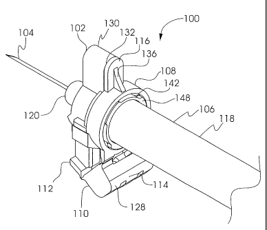
FIGURE 1 is a cutaway perspective view of a medical needle shield apparatus in
accordance with the principles of the present disclosure;
4
CA 02508360 2005-06-01
WO 2004/050150 PCT/US2003/038080
FIGURE 2 is an exploded perspective view of the medical needle shield
apparatus
shown in FIGURE 1;
FIGURE 3 is a partially exploded perspective view of the medical needle shield
apparatus shown in FIGURE 1;
FIGURE 4 is a cutaway perspective view of an alternate embodiment of the
medical
needle shield apparatus shown in FIGURE 1;
FIGURE 5 is an exploded perspective view of the medical needle shield
apparatus
shown in FIGURE 4;
FIGURE 6 is a perspective view of another alternate embodiment of the medical
needle safety shield apparatus shown in FIGURE 1;
FIGURE 7 is a partially exploded perspective view of the medical needle shield
apparatus shown in FIGURE 6;
FIGURE 8 is an exploded perspective view of the medical needle shield
apparatus
shown in FIGURE 6;
FIGURE 9 is an exploded perspective view of alternate embodiment of the
medical
needle shield apparatus shown in FIGURE 6;
FIGURE 10 is an exploded perspective view of another alternate embodiment of
the
medical needle shield apparatus shown in FIGURE 6;
FIGURE 11 is a perspective view of another alternate embodiment of the medical
needle shield apparatus shown in FIGURE 6;
FIGURE 12 is a partially exploded perspective view of the medical needle
shield
apparatus shown in FIGURE 11;
FIGURE 13 is an exploded perspective view of the medical needle shield
apparatus
shown in FIGURE 11; and
FIGURE 14 is a perspective view of another alternate embodiment of the medical
needle shield apparatus shown in FIGURE 6.
5
CA 02508360 2005-06-01
WO 2004/050150 PCT/US2003/038080
DETAILED DESCRIPTION OF THE EXEMPLARY EMBODIMENTS
The exemplary embodiments of the medical needle shield apparatus and the
methods
of operation disclosed herein are discussed in terms of medical needles for
infusion of
intravenous fluids, medication infusion and fluid collection, and more
particularly, in terms
of a medical needle shield device employed with a needle shield apparatus
associated with a
needle cannula to prevent damage to the needle and possible hazardous exposure
to the
needle cannula, for example, through an inadvertent needle stick. It is
contemplated that
the needle cannula may be shielded during use including storage, transport,
fluid infusion
and/or collection, subsequent thereto, etc. It is envisioned that the present
disclosure,
however, finds application to a wide variety of cannula needles and devices
for the infusion
of preventive medications, medicaments, therapeutics, etc. to a subject. It is
also envisioned
that the present disclosure may be employed for collection of body fluids
including those
employed during procedures relating to phlebotomy, digestive, intestinal,
urinary,
veterinary, etc. It is also contemplated that the medical needle shield device
may be utilized
with other medical needle applications including feeding devices, phlebotomy
devices,
catheters, catheter introducers, guide wire introducers, spinal and epidural,
biopsy,
aphaeresis, dialysis, blood donor, Veress needles, Huber needles, etc.
In the discussion that follows, the term "proximal" refers to a portion of a
structure
that is closer to a clinician, and the term "distal" refers to a portion that
is further from the
clinician. As used herein, the term "subject" refers to a patient that
receives infusions or has
blood and/or fluid collected therefrom using the medical needle shield
apparatus.
According to the present disclosure, the term "clinician" refers to an
individual
administering an infusion, performing fluid collection, installing or removing
a needle
cannula from a medical needle shield apparatus and may include support
personnel.
The following discussion includes a description of the medical needle shield
apparatus, in accordance with the present disclosure. Reference will now be
made in detail
to the exemplary embodiments of the disclosure, which are illustrated in the
accompanying
figures.
Turning now to the figures, wherein like components are designated by like
reference numerals throughout the several views. Referring initially to
FIGURES 1-4,
there is illustrated a medical needle shield apparatus 100 including a first
cylinder, such as,
for example, a shield 102 extensible from a retracted position to an extended
position for
6
CA 02508360 2005-06-01
WO 2004/050150 PCT/US2003/038080
enclosing a distal end of a needle 104 of a medical needle device 106. Shield
102 includes
a collar 108 mounted to medical needle device 106. A proximal portion, such
as, for
example, proximal segment 110 extends from collar 108. A distal portion such
as, for
example, distal segment 112 extends from proximal segment 110. Distal segment
112 is
configured to enclose the distal end of needle 104.
It is contemplated that shield 102 may include one or a plurality of segments.
Proximal portion 110 includes an engagement surface 114, which is engageable
to urge
shield 102 from the retracted position to the extended position. Collar 108
includes a guard
116 which extends from collar 108 and is disposed adjacent to distal segment
112, when
shield 102 is in the retracted position. This configuration advantageously
prevents the
inadvertent extension of shield 102 via engagement of distal portion 112.
The components of the medical needle shield apparatus can be fabricated from a
material suitable for medical applications, such as, for example, polymerics
or metals, such
as stainless steel, depending on the particular medical application and/or
preference of a
clinician. Semi-rigid and rigid polymerics are contemplated for fabrication,
as well as
resilient materials, such as molded medical grade polypropylene. However, one
skilled in
the art will realize that other materials and fabrication methods suitable for
assembly and
manufacture, in accordance with the present disclosure, also would be
appropriate.
Collar 108 is circumferentially disposed about medical needle device 106. It
is
envisioned that collar 108 may have various cross-sectional configurations
corresponding to
the configuration of medical needle device 106. Guard 116 extends radially
outward from
collar 108 and has a configuration corresponding to nose portion 130. This
adjacent
configuration prevents axial engagement with distal segment 112 thereby
preventing
inadvertent activation of shield 102. It is envisioned that guard 116 may be
variously
configured and dimensioned to prevent inadvertent activation of shield 102.
Guard 116 may include a guard support 136 that provides increased strength to
guard 116 for withstanding inadvertent engagement. Guard support 136 has an
angular
support configuration and may be variously sized and geometrically configured
according to
the requirements of a particular needle application. Guard 116 may be
monolithically
formed with collar 108 or integrally assembled therewith via snap fit,
adhesive, etc.
Medical needle device 106 includes, for example, a syringe 118. Syringe 118
has a
needle cannula 104 extending therefrom via a needle mount 120.
7
CA 02508360 2005-06-01
WO 2004/050150 PCT/US2003/038080
Distal segment 112 articulates from proximal segment 110 for extension of
shield
102 to the extended position. Engagement surface 114 of proximal segment 110
may
include a manual actuator 128. Manual actuator 128 is engageable by a
clinician for urging
shield 102 to the extended position from the retracted position. Manual
actuator 128 is
articulated from collar 108. As manual actuator 128 is engaged, proximal
segment 110
forces distal segment 112 to move distally in a generally axial direction such
that distal
segment 112 engages needle cannula 104 to facilitate extension of shield 102.
Distal
segment 112 includes a nose portion 130 having a planar surface 132. In the
extended
position of shield 102, nose portion 130 substantially encloses the distal end
of needle 104
in cooperation with planar surface 132.
Collar 108 has an inner surface 142 that defines a collar cavity 126. Inner
surface
142 includes at least one first interlock, such as collar stops 146 that
project radially inward.
Collar stops 146 are uniformly raised within collar cavity 126 for engagement
with a second
cylinder, such as, for example, a mounting ring 148. This configuration
facilitates mounting
of shield 102 with syringe 118. It is envisioned that one or a plurality of
collar stops 146
may be used. It is further envisioned that collar stops 146 may be raised or
project in a non-
uniform manner, such as, for example, staggered, offset, undulating, etc., to
include an
annular ring.
Mounting ring 148 is configured for mounting with syringe 118. This
configuration
advantageously facilitates mounting shield 102 with syringe 118. Mounting ring
148 has an
outer surface 150 that includes at least one second interlock, such as a
plurality of radially
outward projecting proximal stops 162 and a plurality of radially outward
projecting distal
stops 160. Proximal stops 162 and distal stops 160 are equidistantly disposed,
circumferentially, about outer surface 150. Proximal stops 162 and distal
stops 160 are
uniformly raised from outer surface 150 for disposal within collar cavity 126.
It is
contemplated that one or a plurality of stops 162, 160 may be employed. It is
further
contemplated that stops 162, 160 may be raised or project in a non-uniform
manner, such
as, for example, staggered offset, undulating, etc., to include an annular
ring. The first and
second interlocks prevent movement in both proximal and axial directions. A
third
interlock may be added to prevent rotational movement.
Mounting ring 148 may be mounted to syringe 118 via an adhesive, such as, for
example, pressure-sensitive adhesive, ultraviolet light-activated adhesive,
hot-glue adhesive,
1-part and/or 2-part adhesive, rubber cement, "super glue" type adhesives,
glue stick type
8
CA 02508360 2005-06-01
WO 2004/050150 PCT/US2003/038080
adhesives, air-dry adhesives, press-fit, etc. It is envisioned that no
mounting ring may be
used. Collar 108 may be similarly mounted to syringe 118.
Collar 108 is mounted for relative rotational movement with mounting ring 148
such
that outer surface 150 is disposed within collar cavity 126. Collar stops 146
are disposed
adjacent to outer surface 150. Collar 108 is rotated relative to mounting ring
148 such that
collar stops 146 are oriented in an interlocking arrangement with proximal
stops 162 and
distal stops 160. Thus, proximal stops 162 are aligned with collar stops 146
to prevent
distal axial movement, relative to a longitudinal axis of syringe 118, of
collar 108. Distal
stops 160 are aligned with collar stops 146 to prevent proximal axial movement
of collar
108.
This configuration advantageously prevents removal of shield 102 from syringe
118.
Further, this configuration avoids impedance of administration of fluids via
medical needle
device 106, during, for example, low-angle subcutaneous injections, etc. Thus,
collar 108 is
rotatable relative to mounting ring 148, which is mounted to syringe 118,
facilitating
orientation of the needle bevel of needle cannula 104. This allows selective
orientation of
the needle bevel relative to shield 102 such that shield 102 does not
interfere with
positioning during an administration procedure employing syringe 118. It is
contemplated
that the first cylinder may include shield 102 or mounting ring 148, and that
the second
cylinder may include shield 102 or mounting ring 148.
Referring to FIGURES 4 and 5, an alternate embodiment of mounting ring 148 is
shown, similar to that described. Outer surface 150 of mounting ring 148 has a
collar
portion 170 and a clampable portion 172 extending therefrom. Proximal stops
162 and
distal stops 160 are formed with outer surface 150. Clampable portion 172 is
configured
for receiving engagement with a clamp ring 166. Correspondingly, clamp ring
166 defines
a clamp cavity 168 for disposal of clampable portion 172 therein. Mounting
ring 148 is
disposed within collar cavity 126, similar to that described. Clamp ring 166
is configured as
a two ear crimp clamp. It is contemplated that clamp ring 166 may be
alternatively
configured as a one ear crimp clamp, stepless ear clamp, spring clamp, push
retainer, push
cap, etc.
Clamp ring 166 is manipulated for orientation with syringe 118. Mounting ring
148
is mounted with syringe 118, similar to that described. Clamp ring 166 is fit
over
clampable portion 172 of mounting ring 148 such that mounting ring 148 is
firmly affixed
9
CA 02508360 2005-06-01
WO 2004/050150 PCT/US2003/038080
to syringe 118. It is envisioned that clamp ring 166 may be mounted to an
interior surface
or to outer surface 150 of mounting ring 148. It is further envisioned that
clamp ring 166
may be directly employed with collar 108 of shield 102 and may similarly be
mounted to an
interior surface or an outer surface of collar 108. Clamp ring 166 and collar
108 may be
configured so as to create a press fit in which clamp ring 166 and collar 108
are pressed
onto syringe 118 as a unit.
Referring to FIGURES 6-8, another alternate embodiment of mounting ring 148 is
shown, similar to those described. Mounting ring 148 includes a cover 174 that
has a first
cover portion 176 attachable with a second cover portion 178. Cover 174
defines a cover
cavity 182 and includes a cover base 180 at a proximal end thereof. Cover 174,
and
correspondingly cover cavity 182, are configured for attachment to syringe
118. Mounting
ring 148 includes proximal stops 162 and distal stops 160, similar to those
described, which
cooperate with collar 108 to facilitate mounting of shield 102 with syringe
118, as
discussed.
Cover base 180 includes a base opening 184 and a grip channel 186. Grip
channel
186 includes grip channel lips 188 that define a grip channel opening 190
configured for
receipt of a finger grip of syringe 118. Grip channel lips 188 support the
finger grip to
facilitate mounting of syringe 118 with mounting ring 148 and prevent rotation
of syringe
118 relative to cover 174. It is envisioned that grip channel lips 188 may be
configured and
dimensioned to support various finger grip configurations, for example, as
show FIGURE
14. It is also contemplated that the finger grip configurations may be
configured to retain a
plunger within the syringe barrel as shown in FIGURE 14. It is further
envisioned that grip
channel 186 may include clips, clamps, etc. to facilitate mounting to syringe
118.
First cover portion 176 and second cover portion 178 are similarly configured
and
dimensioned for mounting to syringe 118. Portions 176, 178 are elongated half
cylinders
that extend from a distal end to a proximal end. It is contemplated that cover
174 may have
various cross-sectional configurations, such as, for example, polygonal,
elliptical, etc. It is
further contemplated that first cover portion 176 may be of a dissimilar
configuration and
dimension than second cover portion 178. A plurality of cover portions may be
used or
alternatively, each cover portion may be assembled from a plurality of
sections. In an
alternate embodiment, as shown in FIGURE 9, mounting ring 148 includes a cover
174
having a monolithic tube-type sleeve configuration that slides onto syringe
118 for support
thereof. In another alternate embodiment, as shown in FIGURE 10, mounting ring
148
CA 02508360 2005-06-01
WO 2004/050150 PCT/US2003/038080
includes a cover 174 having a first cover portion 176 and a second cover
portion 178 that
are hingedly connected along its longitudinal length. This one piece clam-
shell type
configuration is mounted about syringe 118 for support thereof in a locked
engagement that
employs male tabs 192 and female slots 194.
First cover portion 176 includes a first portion connection device, such as,
for
example, male tabs 192 and a second portion connection device, such as, for
example,
female slots 194, which are alternately disposed on either side and at the
proximal and distal
ends thereof. Second cover portion 178, reciprocal to first cover portion 176,
includes male
tabs 192 and female slots 194. Tabs 192 and slots 194 of first cover portion
176 are
disposed with corresponding slots 194 and tabs 192 of second cover portion
178,
respectively, such that first cover portion 176 can be assembled and locked
with second
cover portion 178. Upon assembly of first cover portion 176 and second cover
portion 178,
male tabs 192 engage and latch with female slots 194. It is envisioned that
one or a
plurality of male tab 192/female slot 194 combinations may be employed. It is
further
envisioned that the male tab 192/female slot 194 combinations may be variously
disposed
about cover 174. It is contemplated that the cover portions could be joined
through
adhesive or welding, e.g., sonic, RF, thermal, etc.
Syringe 118 is disposed within cover cavity 182 such that needle cannula 104
protrudes from the distal end of cover 174 and the finger grip of syringe 118
protrudes from
the proximal end cover 174. This configuration advantageously allows syringe
118 and
syringe cover 174 to rotate relative to collar 108. A rubber sheath is mounted
about needle
cannula 104 and to needle mount 120 to prevent hazardous exposure to the
distal end of
needle cannula 104.
Referring to FIGURES 11-13, in an alternate embodiment, syringe 118 includes a
plunger 198 having a plunger rod 196 that extends to a plunger head 200.
Plunger 198 is
assembled with the barrel of syringe 118 so that upon manipulation of plunger
198, fluids
are expelled from syringe 118.
Grip channel lips 188 extend transverse to a longitudinal axis of syringe 118
and
radially inward. Grip channel lips 188 converge to define an opening that
slidably receives
plunger rod 196. The opening, however, is sufficiently dimensioned to prevent
proximal
movement of plunger head 200 beyond grip channel 186. This configuration
11
CA 02508360 2005-06-01
WO 2004/050150 PCT/US2003/038080
advantageously prevents plunger head 200 from being withdrawn from the barrel
of syringe
118 and avoids accidental removal of plunger 198 from syringe 118.
The invention of the present disclosure may be embodied in other specific
forms
without departing from the spirit or essential characteristics thereof. The
present
embodiments are therefore to be considered in all respects as illustrative and
not restrictive,
the scope of the invention being indicated by the appended claims rather than
by the
foregoing description, and all changes which come within the meaning and range
of
equivalency of the claims are therefore intended to be embraced therein.
12