Note: Descriptions are shown in the official language in which they were submitted.
CA 02508379 2005-05-27
Q.2AF00
A WINDSCREEN WIPER DEVICE
The invention relates to a windscreen wiper device comprising
at least one yoke which is attached to a carrier in such a
manner as to be capable of pivotating movement about a first
pivot axis, wherein both said carrier and said yoke have a
substantially U-shaped cross-section at the location of their
interconnection, said windscreen wiper device further
comprising a oscillating arm pivotally connected to said
carrier about a second pivot axis near one end, wherein said
carrier is provided, at the location of said second pivot
axis, with a transverse shaft.
A windscreen wiper device of this type is generally known and
is usually provided with a plurality of yokes, in order to
ensure that a wiper blade thereof is in contact with a,
usually curved, windscreen along its entire length. Each yoke
is thereby pivoted to the end of a carrier in its central
portion, which carrier itself may also be a yoke. Usually said
carrier and yokels) are made of metal, so that a plastic part
often called "spacer" is interposed at the location of the
connection of a carrier and a yoke, said plastic part being
stationary with respect to a carrier associated therewith. The
oscillating arm has a hook-shaped end hooking up the shaft of
the carrier.
A disadvantage of such a known windscreen wiper device is
that, due to high forces exerted in practice on the connection
between the oscillating arm and the carrier, the reliability
of said connection appears to diminish with the passage of
time, resulting in play between the oscillating arm and the
carrier. Such a play in practice has proven to lead to
frictional contact between these parts and therefore leads to
wear.
CA 02508379 2005-05-27
2
The object of the invention is to overcome these drawbacks of
the prior art as indicated above, in particular to provide a
windscreen wiper device wherein the carrier and the
oscillating arm are interconnected in a simple though durable
and solid manner.
In order to accomplish that objective a windscreen wiper
device of the type referred to in the introduction is
characterized according to the invention in that said
oscillating arm and said carrier are interconnected with the
interposition of a joint part, wherein said joint part
comprises at least one resilient tongue engaging in a
correspondingly shaped hole provided in said oscillating arm.
This makes it possible to realize an effectively operating and
reliable joint being extremely wear resistant, whilst
minimizing the number of parts.
In one preferred embodiment of a windscreen wiper device in
accordance with the invention said oscillating arm has an at
least substantially U-shaped cross-section at the location of
its connection to said joint part, wherein said hole is
provided in a base of said U-shaped cross-section.
In another preferred embodiment of a windscreen wiper device
according to the invention said joint part comprises at least
two lateral resilient tongues extending outwardly, wherein
said oscillating arm has an at least substantially U-shaped
cross-section at the location of its connection to said joint
part, and wherein each tongue engages in a correspondingly
shaped hole provided in a leg of said U-shaped cross-section.
In another preferred embodiment of a windscreen wiper device
in accordance with the invention said holes) has/have a
closed circumference. Such (a) closed holes) enhances) the
CA 02508379 2005-05-27
3
retention of the oscillating arm onto the carrier in all
directions, particularly both horizontally and vertically.
In another preferred embodiment of a windscreen wiper device
according to the invention said oscillating arm has an at
least substantially U-shaped cross-section at the location of
its connection to said joint part, wherein each leg of said U-
shaped cross-section comprises clamping members which engage
around longitudinal sides of said joint part that face away
from each other. These clamping members being preferably
formed as inwardly bended edges of the U-shaped cross-section
serve to further enhance the retention of the oscillating arm
onto the carrier in vertical direction, that is perpendicular
to the longitudinal direction of the oscillating arm.
In another preferred embodiment of a windscreen wiper device
in accordance with the invention said shaft pivotally engages
in said joint part. In particular, said shaft can be pivotally
mounted in at least one correspondingly shaped recess in said
joint part.
In another preferred embodiment of a windscreen wiper device
according to the invention said shaft can be snapped into said
recess.
In another preferred embodiment of a windscreen wiper device
in accordance with the invention said shaft is dimensioned
such that it can be passed through an insertion opening of the
recess from an at least substantially perpendicular position
of said oscillating arm with respect to said carrier, and be
locked in position in said recess from an at least
substantially parallel position of said oscillating arm with
respect to said carrier. In the mounting position, the shaft
can be freely inserted into the insertion opening of the
recess and subsequently be mounted in said recess, whilst in
the operative position the shaft is locked in position in said
CA 02508379 2005-05-27
4
recess, so that it cannot move out of said recess via the
insertion opening.
In another preferred embodiment of a windscreen wiper device
according to the invention said shaft is formed by two
protrusions each extending inwardly on a longitudinal side of
said carrier. Preferably said protrusions are cylindrical and
form two cylindrical bearing surfaces. The two protrusions
that function as bearing surfaces are spaced far apart, so
that the forces that are exerted on said bearing surfaces will
be relatively low.
In another preferred embodiment of a windscreen wiper device
in accordance with the invention said shaft is formed by a pin
extending from one longitudinal side to another longitudinal
side of said carrier.
In another preferred embodiment of a windscreen wiper device
according to the invention said joint part is made of plastic,
which includes any synthetic material having some flexibility.
The invention will now be explained in more detail with
reference to figures illustrated in a drawing, wherein:
- Figure 1a is a perspective, schematic view of a preferred
embodiment of a windscreen wiper device in accordance with
the invention;
- Figure lb is a top view of a windscreen wiper device of
figure la;
- Figures 2, 3 and 4 are several perspective, schematic
views of a joint part used in a windscreen wiper device of
figure la;
CA 02508379 2005-05-27
- Figure 5 is a perspective, schematic view of a part of an
oscillating arm used in a windscreen wiper device of
figures la and lb, seen from above; and
5 - Figure 6 is a perspective, schematic view of an end of an
oscillating arm used in figure 5.
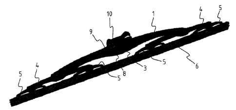
Figure la shows a perspective view of a windscreen wiper
device equipped with a first yoke 1 which can be pivotally
attached to an oscillating arm 2 at the location of a pivot
axis 3. The first yoke 1 functions as a carrier of two
secondary yokes 4, which secondary yokes 4 function as
carriers of four tertiary yokes 5. All yokes are pivot-mounted
in their respective carriers, so that a force exerted at the
location of the pivot axis 3 is distributed more or less
evenly over the ends of the tertiary yokes 5, capable of being
transferred to a rubber wiping element 6, which can be fitted
on the ends of the tertiary yokes 5.
As can be seen from figure lb, the first yoke 1 is provided,
at the location of the pivot axis 3, with a shaft in the form
of a transverse pin 7 extending from one longitudinal side 8
to another longitudinal side 9 of the first yoke 1. A joint
part 10 is snapped ("clipped") onto the pin 7, in such a
manner that the pin 7 is pivotally mounted in a
correspondingly shaped recess 11 in a downwardly extending
portion 12 of the joint part 10 (figures 2 and 3).
With reference to figures 2, 3, 4, 5 and 6 the oscillating arm
2 has a U-shaped cross-section at the location of its
connection to the joint part 10, so that a resilient tongue 13
of the joint part 10 engages in an identically shaped hole 14
provided in a base 15 of the U-shaped cross-section. While
mounting the oscillating arm 2 onto the first yoke 1/joint
part 10, the resilient tongue 13 is initially pushed against a
spring force and then allowed to spring back into the hole 14,
CA 02508379 2005-05-27
6
thus snapping, that is clipping the resilient tongue 13 into
the hole 14. This is a so-called bayonet-connection.
Each leg 16 of the U-shaped cross-section comprises clamping
members which engage round longitudinal sides of the joint
part 10 that face away from each other. In figure 6 these
clamping members are formed as inwardly bended edges 17
integral with the legs 16 of the U-shaped cross-section,
serving to further enhance the retention of the oscillating
arm 2 onto the first yoke 1/joint part 10 in vertical
direction, that is perpendicular to the longitudinal direction
of the oscillating arm 2. The bended edges 17 rest in small
grooves 18 of the longitudinal sides of the joint part 10. At
the location of the bended edges 17 the oscillating arm 2 has
a more or less C-shaped cross-section. The oscillating arm 2
is clipped onto the joint part 10 through a longitudinal
movement of the oscillating arm 2.
The invention is not restricted to the variants shown in the
drawing, but is also extends to other embodiments that fall
within the scope of the appended claims. For example, a
skilled person would realize that the resilient tongue 13
could also extend laterally outwardly, so that the resilient
tongue 13 engages in an identically shaped hole 14 provided in
a leg 16 of the U-shaped cross-section.