Note: Descriptions are shown in the official language in which they were submitted.
CA 02508430 2005-05-26
- 1 -
Joystick arrangement
The invention concerns a joystick arrangement with a basic
unit and a movable handle unit, which comprises at least
one electrical function element with an energy supply con-
nection and an endpoint of a wireless signal transmission
path.
Such a joystick arrangement is known from US 6,550,562 32.
Via three wires, the electrical function element is con-
nected with a control device in the basic unit. The three
wires comprise voltage, mass and a serial data transmis-
sion wire. The data transmission can also be wireless.
Such joystick arrangements are frequently used for con-
trolling hydraulic machines. By moving the handle unit,
which can also be called handle, hydraulic motors, for ex-
ample piston-cylinder units, are activated in a desired
direction, the activation of the handle unit in relation
to the basic unit usually also being able to influence the
speed, at which the motor works. The motors, for example,
serve the deflection of an arm on a digger, the lifting of
the load arm of a fork lift or the driving of the machine,
when a self-propelled driven machine is concerned.
Further, such a handle unit has additional function ele-
ments in the form of buttons, switches, wheels etc., with
which the operator can control further functions. While
the activation of the handle unit in relation to the basic
unit can usually be determined by a sensor arrangement,
which is integrated in the basic unit, these signals from
CA 02508430 2005-05-26
- 2 -
the additional function element or elements have to be
transmitted to an evaluation system.
When mounting a joystick arrangement, it is necessary,
also when a wireless signal transmission path is used, to
ensure that the electrical function element is supplied
with the required electrical energy. For this purpose, it
is necessary to create an electrical wire connection be-
fore the mounting, which should then be as invisible as
possible, when the handle unit is mounted on the basic
unit. This means that the installer will have to be rather
skilled to perform the mounting.
The invention is based on the task of simplifying the
mounting.
With a joystick arrangement as mentioned in the introduc-
tion, this task is solved in that the energy supply con-
nection is connected with a power receiver located in the
handle unit, which power receiver can be supplied with en-
ergy via a wireless power transmission path.
With this embodiment no electrical wires are required at
all to create a connection between the basic unit and the
electrical function element. It is sufficient to mount the
handle unit mechanically on the basic unit, that is, to
connect it with the basic unit or otherwise locate it near
the basic unit. The energy, for example electrical energy,
which is required for the operation of the function ele-
ment, is transmitted wirelessly, so that here electrical
wires are dispensable. Within certain limits, a wireless
energy transmission is possible without problems. Particu-
larly, when the electrical energy consumption of the elec-
CA 02508430 2006-11-21
- 3 -
trical function element is limited, such an energy trans-
mission can be realised in a wireless manner without large
efforts.
It is preferred that the energy transmission path has a
high frequency band. With a high frequency field, electri-
cal energies can be transmitted over certain distances
with a relatively good efficiency. The term "high fre-
quency field" is here used in a rather wide sense. It
reaches from approximately 100 KHz to 20 MHz. The higher
the frequency is, the more power can be transmitted. The
energy can also be transmitted with light; also a
BLUETOOTHO technique could be imagined.
The energy can also be transmitted in other ways, for ex-
ample acoustically or by pressure. In this case, an energy
conversion into electrical energy is provided in the han-
dle unit.
Preferably, a power transmitter is located in the basic
unit. In this case, the power transmission path is auto-
matically kept short, that is, the spatial distance be-
tween the power transmitter and the power receiver remains
small. Particularly with higher frequencies, this embodi-
ment keeps the risk of interferences, which could pene-
trate to the environment, small. Further, the efficiency
of the power transmission is increased.
Preferably, the power receiver has an energy accumulator,
for example a battery or a capacitor. In a manner of
speaking, the battery or the capacitor serves as energy
buffer for periods, in which the power transmission via
the wireless power transmission path is disrupted, meaning
CA 02508430 2005-05-26
- 4 -
that the electrical power cannot be transmitted with the
required intensity. During normal operation, the battery
can be constantly charged, so that it is ensured that the
required electrical power is constantly available.
Preferably, the electrical function element is connected
with a circuit in the handle unit, which has a permanent,
variable memory. In this memory, data can thus be stored,
which would then not be lost during a malfunction or a
failure of the electrical power transmission. For example,
certain operation parameters can be stored in the memory,
which are sized for the individual machine. When the ma-
chine is turned off, the power transmitter will no longer
transmit. However, the operation parameters will be main-
tained. This store can also be used for simplifying the
mounting. In a manufacturing step prior to the final
mounting, the handle unit can be supplied with the re-
quired parameters, or with programs, which are favourable
for the control of the machine. When, then, the handle
unit is mounted on the basic unit, the programs or data
for the operation of the machine are available right away.
An update can easily be made in that the handle unit is
replaced by another handle unit with new data or programs.
Preferably, the signal transmission path has a second end
point, which is connected with a bus interface. Thus, it
is possible to connect the electrical function element di-
rectly with a bus, for example a CAN-bus, which is located
on the machine. This is particularly advantageous, when
the machine is a self-propelled driven machine, as the use
of CAN-busses is common in vehicles. Thus, via the joy-
stick it is possible to intervene in practically the com-
plete system of the vehicle or the machine.
CA 02508430 2005-05-26
- 5 -
Preferably, the handle unit is detachably.connected with
the basic unit. The connection can, for example, be real-
ised by means of a snap or a catch connection. Also some
kind of bayonet connection is possible. If required, eas-
ily activated, auxiliary connecting parts can be used, for
example a flap or a union nut. When the handle unit is de-
tachably connected with the basic unit, a number of advan-
tages occur, which will be described below.
For example, the basic unit is optionally connected with
one of several handle units, which have different embodi-
ments. The users often want a handle unit with special
buttons, scroll buttons, adjustment wheels, switches or
the like, a special location of these activation elements
or the like. This is easily realised with the detachable
connection of the handle unit on the basic unit. In each
case, the signal and energy transmission can have the same
embodiment, namely wireless. In order to be able to adapt
to the wishes of a user, it is sufficient to use a handle
unit, which has the corresponding external design.
It is also advantageous, when the basic unit is optionally
connectable with one of several handle units, in which the
individual electrical function elements have different
characteristics. For example, in connection with the acti-
vation of an activation arrangement, which releases or
controls the electrical function element, different re-
sponse times or different ramp functions or other differ-
ent responses can be built in. The user can then have a
handle element, which is adapted to him and satisfies his
wishes.
CA 02508430 2005-05-26
- 6 -
It is particularly advantageous, when driver-specific data
are stored in at least one handle element, said data being
automatically transferable to the basic unit when mounting
the handle unit. These driver-specific data can, for exam-
ple, be the response times or the functions mentioned
above. However, also seat positions or similar things on
the vehicle can also be stored in the handle unit. Each
driver then has his own handle unit. When the driver
mounts his handle unit on the basic unit, the vehicle or
the driven machine is automatically adjusted in accordance
with his programmed settings, for example, the seat posi-
tion can be set correctly, the chair back inclination of
the seat can be set accordingly, the position of the driv-
ing mirrors can be set, etc. Additional measures are not
required. It is sufficient, when the driver mounts his
handle unit on the basic unit.
It is also advantageous, when at least one electrical
function element has a theft protection function, which
can only be deactivated, when a handle unit is mounted.
When the machine is, for example, a tractor, the driver
can take along the handle unit when leaving the tractor,
thus ensuring that the tractor is theft protected. For ex-
ample, a starter killer is activated, so that the motor of
the tractor can no longer be started.
It is also advantageous, when the basic unit is detachably
mounted on a vehicle or a driven machine. Then, a remote
control can be realised in a simple manner. The basic unit
merely has to be detached from the machine or the vehicle.
The driver can then position himself outside the machine
and then possibly has a better view of the functions to be
performed by the machine.
CA 02508430 2005-05-26
- 7 -
Preferably, at least one additional basic unit is provided,
and the handle unit communicates optionally with one of
the basic units. In this case, the vehicle or the driven
machine can be controlled from different locations. For
example, it can then be ensured that the machine is
stopped, when the handle unit is removed from a basic unit.
The machine then cannot be operated again, until the han-
dle unit communicates with another basic unit. It may even
be ensured that the handle element causes other reactions,
depending on the location of the basic unit. For example,
the posture of the operator can be considered. When sit-
ting, an operator will handle the handle unit differently
than when standing.
It is also advantageous that the handle unit has a display.
Such a display can, for example, be a liquid crystal dis-
play (LCD display). In this display, also buttons or con-
tact sensitive spots can be imagined, which can then be
reconfigured by the user to different functions, as it is,
for example, known from mobile phones. It is also possible
to provide light in the function elements, for example,
buttons or switches, so that the light is turned on, when
a button or a switch is activated.
Preferably, the function element can be configured via the
signal transmission path. Then, the function element can,
for example, be adapted to different vehicles or driven
machines, in which connection it is of course possible to
consider previously stored user-specific settings.
CA 02508430 2005-05-26
- 8 -
In the following, the invention is described on the basis
of a preferred embodiment in connection with the drawings,
showing:
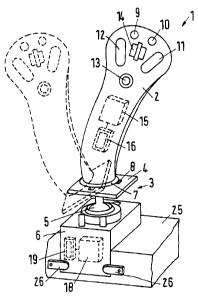
Fig. 1 a schematic view of a joystick arrangement
Fig. 2 a block schematic diagram
A joystick arrangement 1 has a handle unit 2, which is de-
tachably fixed on a basic unit 3. For this purpose, the
basic unit 3 has a mounting plate 4, which is supported on
a housing 6 via a ball joint, so that the handle unit 2
can be displaced from the position shown with full lines
to a position which is shown with dotted lines. Shown is a
displacement in one direction, in fact, however, the han-
dle unit 2 can be displaced in random directions in rela-
tion to the housing 6.
The mounting plate has a mounting opening 7, into which
the handle unit 2 can be inserted. Distributed around the
mounting opening 7 are several radially extending recesses
8, into which radial pins, not shown in detail, on the
handle unit 2 can engage, when the handle unit 2 is
mounted. After inserting the handle unit 2 into the mount-
ing plate 4, the handle unit 2 must be turned, for example
by 45 , in relation to the mounting plate 4 to ensure a
safe fixing. Thus, the handle unit 2 is detachably fixed
on the basic unit 3, here with some kind of bayonet con-
nection. Other kinds of mounting, for example with a union
nut or the like, are possible.
In a manner not shown in detail, the mechanical fixing be-
tween the handle unit and the basic unit can even be omit-
CA 02508430 2005-05-26
- 9 -
ted. The handle unit can be moved freely in the room. This
can now be compared with a computer mouse, which is, how-
ever, only movable in two dimensions. The opportunity of
moving the handle unit freely in the room gives a further
comfort feature. It is merely required that the handle
unit and the basis unit can communicate with each other.
By displacement in relation to the housing 6, the handle
unit 2 controls a number of functions of a hydraulic ma-
chine, which is not shown in detail. The machine can be
provided with several drives. A displacement of the handle
unit 2 in relation to the housing 6 in one direction will
activate a drive in one direction or the other, depending
of the displacement direction. The degree of the deflec-
tion is a measure for the power, with which the drive is
activated, for example a measure for an extension movement
of a piston-cylinder arrangement or a measure for the
speed, at which a rotary motor is activated. As the handle
unit 2 can be displaced in several directions in relation
to the housing 6, it is also possible to control more than
one motor, for example two motors.
The handle unit 2 has a number of additional actuation
elements, namely two buttons 9, 10, two switches 11, 12,
and adjustment wheel 14 and a light emitting diode 13. The
location shown here is merely an example. Different users
have different wishes. The mentioned actuation elements 9
to 14 are connected with an electrical function element 15,
which can, for example, have the form of an integrated
circuit. The function element is connected with an antenna
16, which is able to derive energy from a high frequency
field. The high frequency field, which is explained below,
works in the area from 100 KHz to approximately 20 MHz.
CA 02508430 2005-05-26
- 10 -
Preferred frequencies are, for example, 125 KHz or 13 MHz.
In a manner not shown in detail, the function element 15
can have an A/D converter, a microprocessor, a RAM, an
EEPROM, a ROM, oscillators, timers and counters. Also a
multiplexer is possible, when several actuation elements 9
to 14 are connected to the function element 15. The func-
tion element 15 can, for example, be a component group
MLX10111 of the Melexis Microelectronic Systems, Concord
NH, USA.
In a manner not shown in detail, the handle unit can also
have a display, for example an LCD display. This display
may be provided with contact sensitive areas, via which a
user can enter different functions or which he can recon-
figure to different functions. The use of the handle unit
thus gets very flexible.
As can be seen from Fig. 2, the function element can fur-
ther have a battery 17, so that a brief failure of the
power transmission can be buffered via the high frequency
field.
The function element 15 is switchable. On the one hand,
the high frequency field can be operated with 13 MHz, on
the other hand also with 125 KHz. In each case, it is en-
sured that the required electrical power can be transmit-
ted.
The electrical power is provided by a power transmitter 18,
which is located in the housing 6. The power transmitter
18 is connected with an antenna 19. The antenna 19 can
also be integrated in the power transmitter 18. Via the
antenna 19, the power transmitter emits the high frequency
CA 02508430 2006-11-21
- 11 -
field, which is used to transfer the electrical power to
the function element 15.
The power transmitter 18 can, for example, be a component
group MLX90121 of Melexis Microelectronic Systems.
As appears from Fig. 2, a wireless transmission path 20 is
provided between the function element 15 and the power
transmitter 18. Via this path 20, not only the electrical
power is transferred, which is required for driving the
function element 15, but the transmission path 20 is also
used to transfer the signals, which are generated by the
function element 9 to 14, to the housing 6. For this pur-
pose, the power transmitter 18 has a data receiving ar-
rangement. The function element 15 is able to send and re-
ceive data.
Instead of an electrically higher frequent field, the re-
quired energy can also be transferred in a different man-
ner, for example by means of light. For this purpose,
light emitting diodes and corresponding light receivers,
for example light sensitive transistors, would be avail-
able. Also an energy transfer in an acoustic manner or
low-frequent would be possible. Also a BLUETOOTHO
technology could be imagined, so that in principle a
larger distance between the handle unit 2 and the basic
unit 3 would be acceptable. BLUETOOTHO works in the
Gigahertz area.
In any case, some sort of security would be built into the
communication between the handle unit 2 and the basic unit
3, so that the certainty for discovering the determination
of a "false" signal is 100 percent. Such a signal might
trigger an error situation. The security can be ensured by
CA 02508430 2005-05-26
- 12 -
way of hardware. However, it is also possible to ensure it
by means of software.
When such a non-electrical transmission path is available,
it is of course possible not only to transfer the energy,
but also the signals, via this transmission path. In this
case, an energy converter will be required, which converts
the non-electrical signals into electrical signals and
vice versa.
The power receiver 18 is connected via a serial bus 21
with a bus interface 22, which again is connected with a
CAN-bus 23. When the joystick arrangement is mounted on a
vehicle, it gives direct access to the CAN bus and thus to
practically all component groups of the vehicle, which are
connected with the CAN bus.
For the sake of completeness it is mentioned that the
housing 6 has an energy supply 24, which, for example,
supplies the power transmitter 18.
As appears from Fig. 1, not only the handle unit 2 is de-
tachable from the basic unit 3. Also the basic unit 3 is
detachably mounted on a frame 25, the frame 25 being, for
example, part of a vehicle. When the basic unit 3 with the
handle unit2 is removed from the frame 25, it is, in a
manner of speaking, possible to remote-control the vehicle
or machine to be controlled. Safety levers 26 serve the
purpose of fixing the basic unit in the frame 25. Plug
connections, not shown in detail, ensure that the energy
supply 24 and the CAN-bus 23 are connected with the basic
unit 3, when the basic unit 3 is inserted in the frame 25.
CA 02508430 2005-05-26
- 13 -
The embodiment shown gives a number of advantages.
Even when the handle unit 2 is not detachably mounted on
the basic unit 3, the mounting is substantially easier, as
no electrical connections have to be established.
However, additional advantages are involved, when the han-
dle unit 2 is detachably mounted on the basic unit 3. For
example, several handle units 2 can be provided, which are
provided with different arrangements of actuating elements
9 to 14. Many users want a handle unit with special but-
tons or switches or a special location of the buttons, and
with the idea described here, this is possible in a simple
and cost effective manner.
With the handle unit, it is possible to communicate with
the whole machine via the CAN-bus. Particularly when used
in a vehicle, there are many possibilities. Finally, not
only interventions in the actuation of hydraulic motors
are possible, but also, for example, in the injection into
a diesel engine driving a pump, which is provided for the
supply of hydraulic consumers. Thus, the joystick arrange-
ment extends its application field.
When, now, the handle unit 2 can be dismounted from the
basic unit 3, the handle unit 2 can be taken along, when
leaving a self-propelled driven machine, the driven ma-
chine then being theft-protected (starter kill) and locked.
When returning to the driven machine, the handle unit 2 is
inserted in the basic unit 3 again, and the machine is
ready to work.
CA 02508430 2005-05-26
- 14 -
Each user can be provided with his own special handle unit
2, in which his specific data are stored, for example,
seat position, driving mirror position, speed profile and
the like. When, now, the driver or operator inserts the
handle unit 2 into the basic unit 3, the machine is auto-
matically loaded with his desired settings.
It is possible, initially to provide at least one addi-
tional basic unit on the vehicle or on the driven machine.
The handle unit 2 can then removed from the first basic
unit 3 and be fixed on or connected with the additional
basic unit 3. Here it can be imagined that the complete
system blocks the basic unit 3 at the same time, when the
handle unit is removed, so that an undesired actuation is
not possible at all, also when an undesired actuation
takes place in the basic unit. When the handle unit is
then mounted in the other basic unit, specific settings
can also exist here.
In connection with new software actualisations the manu-
facturer could deliver a new handle unit 2. When mounted
in the basic unit 3, a software actualisation would then
take place, which can easily comprise the whole machine or
the whole vehicle, respectively, as a connection from the
handle unit 2 to the CAN-bus of the machine or the vehicle
exists via the wireless transmission path 20.
Also an upload to the handle unit 2 is possible, so that a
certain function element on the handle unit 2 can be pro-
vided with a new function via the transmission path 20.