Note: Descriptions are shown in the official language in which they were submitted.
CA 02508730 2005-06-23
1
ABSORBENT PRODUCT WITH NONPERMEABLE SURFACE SHEET
Technical Field
The present invention relates to an absorbent product.
More precisely, it relates to an absorbent product capable
of preventing the absorbing rate of discharged liquid from
significantly lowering with the elapse of time, and having
a very small re-wet amount.
Background Art
Conventional absorbent products include a liquid-
permeable top sheet positioned on the upper side (the side
nearer to the wearer's body), a liquid-impermeable back
sheet positioned on the lower side (the side away from the
wearer's body), and an absorber positioned between these.
In case discharged liquid such as urine, feces, and body
fluid containing blood (hereinafter referred simply as
"discharged liquid" or "liquid") is supplied to this
absorbent product, the discharged liquid first passes
through the liquid-permeable top sheet and reaches the
absorber. In the absorber, the discharged liquid diffuses
to the lower side, and when it reaches the liquid-
impermeable back sheet, the diffusion ceases. All of the
conventional absorbent products use a discharged liquid
CA 02508730 2005-06-23
2
absorbing mechanism such as this.
However, the conventional absorbent products which use
the aforementioned absorbing mechanism have two major
intrinsic problems. The first problem is that the
absorbing rate is lowered as the absorber's absorption
volume of discharged liquid increases. The second problem
is that the amount of liquid returning from the absorber to
the top sheet, or the re-wet amount, increases as the
absorption volume of discharged liquid grows larger,
especially in the vicinity of the limit of absorbing
capacity. These cause an increase of moisture percentage
on the surface of the wearer's body during and after
discharging of the liquid, making it uncomfortable to keep
it on, easily susceptible to becoming sweaty, as well as
becoming a primary cause of diaper rash.
While on the other hand, in an effort to solve these
problems, diverse suggestions regarding performance,
structure, air-permeability, etc. of the top sheet and the
absorber have been made, but so far no technique reaching
the ultimate solution has been found.
Disclosure of the Invention
An object of the present invention, therefore, is to
provide an absorbent product which is capable of preventing
CA 02508730 2005-06-23
3
the absorbing rate from significantly lowering with the
elapse of time from the start of use to a final stage when
the absorbing capacity of the product reaches a limit, and
has a very small re-wet amount.
The inventors of the present invention, as a result of
research devoted to achieving the above objective, defying
traditional common sense, have discovered that it is
possible, by positioning on the upper side of an absorber a
liquid-impermeable surface sheet in place of a liquid-
permeable top sheet to which the discharged liquid is
supplied, and by designing a structure wherein a flow
passage from the upper side of a surface sheet reaching the
lower portion of an absorber is provided, to realize an
absorbing mechanism that diffuses a part or all of the
discharged liquid from the lower side to the upper side of
an absorber. The inventors of the present invention,
furthermore, have discovered that, by the above absorbing
mechanism, the absorbing rate is prevented from
significantly lowering with the elapse of time, and the re-
wet amount becomes extremely small. Based on this
knowledge, the inventors of the present invention have
completed the present invention.
In other words, the present invention provides the
following: (1) through (34).
CA 02508730 2005-06-23
4
(1) An absorbent product with a liquid-impermeable surface
sheet positioned on the upper side, a liquid-impermeable back
sheet positioned on the lower side, and an absorber containing
super absorbent polymer to absorb discharged liquid positioned
between the surface sheet and the back sheet,
wherein a flow passage is provided to allow a part or all
of the discharged liquid supplied to the surface sheet to a side
of the back sheet of the absorber.
(2) The absorbent product according to (1), wherein the flow
passage is provided in at least one of the following portions
of the absorber; on both front and back ends, on both right and
left ends, and in the center.
(3) The absorbent product according to (1) or (2), wherein the
surface sheet is composed of a single-layer synthetic resin
film.
(4) The absorbent product according to (1) or (2), wherein the
surface sheet is composed of a laminate of a synthetic resin
film and a nonwoven fabric provided on a surface of the upper
side of the synthetic resin film.
(5) The absorbent product according to (3) or (4), wherein the
synthetic resin film has concave and convex portions that
constitute the flow passage.
(6) The absorbent product according to any one of (1) to (5)
CA 02508730 2005-06-23
4a
wherein the surface sheet is positioned in such a way that a
portion of the surface of the upper side of the absorber is
exposed.
(7) The absorbent product according to any one of (1) to (6),
wherein the surface sheet contains a liquid-permeable portion.
(8) The absorbent product according to any one of (1) to (7),
wherein a liquid-permeable guide sheet with the flow passage
is laminated to at least a portion of the surface of the upper
side of the surface sheet.
(9) The absorbent product according to (8), wherein the guide
sheet covers at least a portion of the lateral sides of the
absorber directly or over the surface sheet.
CA 02508730 2005-06-23
(10) The absorbent product according to (8) or (9), wherein
the guide sheet has concave and convex portions that
constitute the flow passage and has apertures in some of or
in all of the convex portions.
(11) The absorbent product according to any one of (1) to
(10), wherein a skin-contact sheet composed of liquid-
permeable nonwoven fabric is laminated to at least a
portion of the surface of the upper side of either the
surface sheet or the guide sheet.
(12) The absorbent product according to any one of (1) to
(11), wherein the back sheet is composed of a synthetic
CA 02508730 2005-06-23
6
resin fi.lm.
(13) The absorbent product according to (12), wherein the
synthetic resin film that constitutes the back sheet has
air-permeability.
(14) The absorbent product according to any one of (1) to
(11), wherein the back sheet is composed of a laminate of a
synthetic resin film and a nonwoven fabric provided on the
surface of the lower side of the synthetic resin film.
(15) The absorbent product according to (14), wherein both
the synthetic resin film and the nonwoven fabric that
constitute the back sheet have air-permeability.
(16) The absorbent product according to (14) or (15),
wherein the synthetic resin film that constitutes the back
sheet has concave and convex portions and has apertures in
some of or in all of the convex portions, and the nonwoven
fabric that constitutes the back sheet is a water-resistant
laminate, of two layers or more, containing one layer or
more than one layer of a spunbond nonwoven fabric and one
layer or more than one layer of meltblown nonwoven fabric.
(17) The absorbent product according to any one of (12) to
(16), wherein the synthetic resin film that constitutes the
back sheet has concave and convex portions constituting a
liquid trap portion on the surface of the upper side
thereof.
CA 02508730 2005-06-23
7
(18) The absorbent product according to any one of (1) to
(17), wherein the absorber is composed of a mixture of
super absorbent polymer and fluffy pulp wrapped with a
liquid-permeable core-wrapping sheet.
(19) The absorbent product according to any one of (1) to
(17), wherein the absorber has two layers of liquid-
permeable nonwoven fabrics and super absorbent polymer
inserted in-between.
(20) The absorbent product according to any one of (1) to
(17), wherein the absorber is constructed by having super
absorbent polymer supported by means of coating on a
liquid-permeable nonwoven fabric.
(21) The absorbent product according to any one of (1) to
(20), wherein a content of the super absorbent polymer in
the absorber is 50wt% or more.
(22) The absorbent product according to any one of (1) to
(21),
wherein an absorbent product main body that can form
an internal space to contain a wearer's objective region
when worn;
housing for an absorber unit adjacent to the
absorbent product main body, continued to the internal
space, and containing the back sheet on an inner wall
thereof; and
CA 02508730 2005-06-23
8
an absorber unit structured by combining at least the
surface sheet and the absorber, being received removably by
the housing for the absorber unit are provided.
(23) The absorbent product according to (22), wherein the
guide sheet is included at least in a portion between the
absorbent product main body and the housing for the
absorber unit.
(24) The absorbent product according to (22) or (23),
wherein a liquid-permeable skin-contact sheet is included
at least in a portion between the absorbent product main
body and the housing for the absorber unit.
(25) The absorbent product according to any one of (22) to
(24),
wherein laminated plural number of the absorber units
are included in the housing for the absorber unit.
(26) The absorbent product according to any one of (1) to
(21),
wherein an absorbent product main body that can form
an internal space to contain a wearer's objective region
when worn; housing for an absorber adjacent to the
absorbent product main body, continued to the internal
space, and containing the back sheet on an inner wall
thereof, and
an absorber received removably by the housing for the
CA 02508730 2005-06-23
9
absorber are provided; and,
furthermore, the surface sheet is included at least
in a portion between the absorbent product main body and
the housing for the absorber.
(27) The absorbent product according to (26), wherein the
guide sheet is laminated on the surface of the upper side
of the surface sheet.
(28) The absorbent product according to (26) or (27),
wherein a liquid-permeable skin-contact sheet is provided
at least on a portion of the surface of the upper side of
the surface sheet or the guide sheet.
(29) The absorbent product according to any one of (26) to
(28), wherein laminated plural number of absorbers are
included in the housing for the absorber.
(30) The absorbent product according to any one of (1) to
(29), wherein a urine-disposing portion extending from the
center to the front section and a feces-disposing portion
extending from the center to the back section are provided
and the surface sheet is provided only at the urine-
disposing portion.
(31) The absorbent product according to (30), wherein a
liquid-impermeable or water-resistant back-flow preventing
sheet is included inside and/or on the upper side of the
absorber, at least at the feces-disposing portion.
CA 02508730 2005-06-23
(32) The absorbent product acc.ording to any one of (1) to
(31), wherein a re-wet amount measured under a load of
0.1psi, 5 minutes after the beginning of the absorption to
allow a sodium chloride solution of 0.9wt% in the amount
equivalent to 50% of the absorbing capacity of the absorber
to be absorbed in the absorber at 25 C under no load, is
5mL or less.
(33) The absorbent product according to (32), wherein the
re-wet amount is 2mL or less.
(34) The absorbent product according to any one of (1) to
(33),
wherein the absorber's absorbing capacity of sodium
chloride solution of 0.9wt% is 300mL or more,
and when saline is added to be absorbed by the
absorber in the amount of lOOmL each time in three separate
additions under no load in every 10 minutes, an average re-
wet amount after three additions is 5mL or less,
and the standard deviation of the re-wet amount is
3mL or less; and
when saline is added to be absorbed by the absorber
in the amount of lOOmL each time in three separate
additions under a load of 0.1psi in every 10 minutes,
the mean absorption time of the three additions is 30
seconds or less,
CA 02508730 2005-06-23
11
and the standard deviation of the absorption time is
2 seconds or less.
Brief Description of Drawings
FIG. 1 is a set of illustrative cross-section views
showing a portion of an example of the absorbent product of
the present invention.
FIG. 2 is a group of illustrative top views and cross-
section views showing a portion of examples of the
absorbent product of the present invention.
FIG. 3 (A) is an illustrative perspective view of an
example of the surface sheet with a large number of
projections and FIG. 3 (B) is its illustrative cross-
section view.
FIGs. 4 (A) and (B) are illustrative cross-section
views, each showing an example of the surface sheet with V-
shape grooves, and FIGs. 4 (C) and (D) are illustrative
cross-section views each showing an example of the ribbed
surface sheet.
FIGs. 5 (A) and (B) are illustrative perspective views,
each showing an example of the surface sheet with V-shape
grooves.
FIG. 6 is a group of illustrative cross-section views,
each showing a portion of examples of the absorbent product
CA 02508730 2005-06-23
12
of the present invention.
FIG. 7 is a group of illustrative top views, each
showing a portion of examples of the absorbent product of
the present invention.
FIG. 8 is an illustrative perspective view showing an
example of the guide sheet that has concave and convex
portions constituting flow passages wherein every convex
portion has an aperture.
FIG. 9 is a group of illustrative views, cross-
sectional (FIGs. 9 (A) through (D)) and perspective (FIG. 9
(E)), showing a portion of examples of the absorbent
product of the present invention.
FIG. 10 is a group of illustrative cross-section views,
each showing a portion of examples of the absorbent product
of the present invention.
FIG. 11 is a set of illustrative top views, each
showing a portion of examples of the absorbent product of
the present invention.
FIG. 12 is a set of illustrative top views, showing
examples of the back sheet used in the present invention.
FIG. 13 is a set of illustrative cross-section views,
each showing a portion of examples of the absorbent product
of the present invention.
FIG. 14 is an illustrative top view showing a portion
CA 02508730 2005-06-23
13
of an example of the absorbent product of the present
invention.
FIG. 15 is a set of illustrative cross-section views
showing examples of a portion of the absorbent product of
the present invention.
FIG. 16 is an illustrative top view showing a portion
of an example of the absorbent product of the present
invention.
FIG. 17 is a group of illustrative top views, each
showing an example of preferred configuration of the back
sheet when the member constituting the back sheet itself
constitutes the housing for the absorber.
FIG. 18 (A) is an illustrative cross-section view
showing an example of laminated plural pieces of absorber
units. FIG. 18 (B) is an illustrative cross-section view
showing an example of laminated plural pieces of absorbers,
and FIG. 18 (C) is an illustrative cross-section view
showing an example of a portion of the absorbent product of
the present invention, including laminated plural pieces of
absorber units.
FIG. 19 is a group of explanatory drawings, each
showing an example of the absorbent product of the present
invention with a member for pulling out.
FIG. 20 is a group of illustrative top views, each
CA 02508730 2005-06-23
14
showing an example of a portion of the absorbent product of
the present invention.
FIG. 21 is an illustrative longitudinal section view
showing an example of a portion of the absorbent product of
the present invention.
FIG. 22 is an illustrative longitudinal section view
showing an example of a portion of the absorbent product of
the present invention.
FIG. 23 is a cross-section view explaining the
behavior of the discharged liquid when it is supplied to an
absorbent product.
FIG. 24 is an illustrative cross-section view of the
absorbent product used in the Examples.
FIG. 25 is a set of explanatory drawings showing the
method of measuring absorbing rate in the Examples.
FIGs. 26 are an illustrative front view and an
illustrative top view showing the absorbent product that
includes plural pieces of absorber units and is used in the
Examples.
FIG. 27 is a set of illustrative cross-section views
of the absorber units used in the Examples.
FIG. 28 is a set of illustrative cross-section views
of the absorbent products using the absorber units shown in
FIG. 27.
CA 02508730 2005-06-23
FIG. 29 is an explanatory drawing showing the method
of measuring the re-wet amount of the absorbent products,
for both urine- and feces-disposing, used in the Examples.
FIG. 30 is a set of illustrative cross-section views
showing a portion of an example of a conventional absorbent
product.
Best Mode for Carrying Out the Invention
Hereinafter, the absorbent products of the present
invention will be described in detail in accordance with
preferred embodiments shown in accompanying drawings. Note
that each drawing used to describe the present invention is
an illustrative drawing and is exaggerated in the thickness
of the absorbent product.
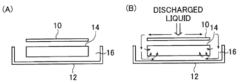
FIG. 1 is a set of illustrative cross-section views
showing a portion of an example of the absorbent product of
the present invention. In FIG. 1, the direction
perpendicular to the surface of the page is the
anteroposterior direction of the absorbent product (in
other words, the direction equivalent to front to back of
the wearer's body when it is worn) (hereinafter the same
applies to all cross-section views). FIG. 1 (A) is an
explanatory drawing of a structure of the absorbent product
of the present invention and FIG. 1(B) is an explanatory
CA 02508730 2005-06-23
16
drawing of the absorbent prodtzct of the present invention
in use.
As shown in FIG. 1 (A), the absorbent product of the
present invention includes a liquid-impermeable surface
sheet 10, a liquid-impermeable back sheet 12, and an
absorber 14 containing super absorbent polymer (hereinafter
also referred to as "SAP"), so that discharged liquid can
be absorbed and positioned between the surface sheet 10 and
the back sheet 12.
When discharged liquid is supplied to the absorbent
product of the present invention, as shown in FIG. 1(B),
because the surface sheet 10 positioned on the upper side
is liquid-impermeable, the discharged liquid moves on the
surface of the surface sheet 10 to the end portions of it.
The discharged liquid that has moved to the end portions of
the surface sheet 10, because the back sheet 12 is liquid-
impermeable, moves along the inner surface of the back
sheet 12 in the flow passage 16 formed between the absorber
14 and the back sheet 12, while a part of it is being
absorbed by the absorber 14, mainly into the bottom side of
the absorber 14. In this way, the discharged liquid is
absorbed by the bottom side of the absorber 14, and then is
diffused to the upper side.
As described above, the absorbent product of the
CA 02508730 2005-06-23
17
present invention is characterized by comprising a flow
passage to allow a part or all of the discharged liquid
supplied to the surface sheet to move to the back sheet
side. It is preferred that this flow passage is provided
in at least one of the following portions of the absorber;
both front and back ends, both right and left ends, and the
center.
FIG. 2 is a group of illustrative top views (FIGs. 2
(A) and (B)) and cross-section views (FIGs. 2 (C) and (D))
showing a portion of examples of the absorbent product of
the present invention. In FIGs. 2 (A) and (B), the top-to-
bottom direction of the page represents the front-to-back
direction of the absorbent product (hereinafter the same
applies to all top views). In FIG. 2, as a matter of
explanatory convenience, only the surface sheet 10, back
sheet 12, and the absorber 14 are shown.
In the absorbent product shown in FIGs. 2 (A) and (C),
the surface sheet 10 fully covers the upper surface of the
absorber 14, and the lateral faces and the lower surface
thereof are fully covered with the back sheet 12. This
absorbent product has the flow passages in all of the
following portions of the absorber 14: the front end
portion A, back end portion B, left end portion C, and the
right end portion D.
CA 02508730 2005-06-23
18
In the absorbent product shown in FIGs. 2 (B) and (D) ,
two absorbers 14 are positioned side by side with a space
in between. Each of two surface sheets 10 fully covers
respectively the upper surface of each of the two absorbers
14, and the outer lateral faces and the lower surface
thereof are fully covered with one sheet of the back sheet
12. This absorbent product has the flow passages in all of
the following portions of the absorber 14: the front end
portion A, back end portion B, left end portion C, right
end portion D, and the center portion E.
FIG. 30 is a set of illustrative cross-section views
showing a portion of an example of a conventional absorbent
product. FIG. 30 (A) is an explanatory drawing showing the
structure of a conventional absorbent product and FIG. 30
(B) is an explanatory drawing of a conventional absorber in
use.
A conventional absorbent product typically includes a
liquid-permeable top sheet 11, a liquid-impermeable back
sheet 12, and an absorber 14 positioned between the top
sheet 11 and the back sheet 12.
When discharged liquid is supplied to a conventional
absorbent product, as shown in FIG. 30 (B), because the top
sheet 11 positioned on the upper side is liquid-permeable,
the discharged liquid passes through the top sheet 11, is
CA 02508730 2005-06-23
19
absorbed by the absorber from the top side thereof, and
then is diffused to the lower side.
In contrast to this, the absorbent product of the
present invention is characterized by realizing an
absorbing mechanism that diffuses a part of or all of the
discharged liquid from the lower side to the upper side of
the absorber 14 by the structure described above. This
mechanism prevents the absorbing rate from significantly
lowering with the elapse of time, and ensures a very small
re-wet amount.
The surface sheet 10 used in the present invention is
liquid-impermeable. In this specification, "liquid-
impermeable" represents a property of not in effect
allowing the discharged liquid to permeate.
There is no limit in particular to the material or
the structure of the surface sheet 10, as long as it is
liquid-impermeable. For example, a single-layer sinthetic
resin film and a laminate of a synthetic resin film and a
nonwoven fabric provided on the surface of the upper side
of the synthetic resin film are preferred. As the
synthetic resin film, a film made of resin such as PE
(polyethylene), PP (polypropylene), PET (polyethylene
terephthalate), polyurethane, or cross-linked PVA
(polyvinyl alcohol) and an air-permeable but not liquid-
CA 02508730 2005-06-23
LO
permeable, in other words, breathable film made of above-
described resins can be typically employed.
One of the preferred embodiments of the synthetic
resin film used for a surface sheet 10 is the type with
concave and convex portions constituting flow passages 16.
However, when the absorbent product of the present
invention has a guide sheet as hereinafter described, even
if the synthetic resin film does not have concave and
convex portions to form flow passages 16, it will also be
suitable for use.
Furthermore, where flat, smooth and relatively soft
synthetic resin film is used as a surface sheet 10, if the
surface of the absorber on which the surface sheet is
positioned has concave and convex portions, the film may be
deformed to be concave and convex, resulting in retention
of the discharged liquid. In this case, however, the
discharged liquid can be quickly moved by pressure-bonding
the synthetic resin film and the upper surface of the
absorber to smooth them out, or by designing a roof-like
structure with a raised center portion and the slopes on
both sides thereof.
As the configuration with concave and convex portions,
the following can be exemplified: a configuration with a
large number of projections, a configuration with grooves
CA 02508730 2005-06-23
21
such as V-shaped or U-shaped grooves, an imbricate
configuration (as imbricate scales), and a ribbed
configuration.
FIG. 3 (A) is an illustrative perspective view of an
example of the surface sheet with a large number of
projections and FIG. 3 (B) is its illustrative cross-
section view.
On the surface sheet 10a, a continuous series of a
large number of concave portions function as flow passages
16 for the discharged liquid. The surface sheet 10a shown
in FIG. 3 has a large number of projections 18 forming
convex portions.
As for the size of the concave and convex portions of
the surface sheet 10a, when taking into account its
handling, cost, etc., it is preferred that the projections
18 forming the convex portions are 0.3mm or greater in
height, more preferably 0.5 to 1.5mm.
The surface sheet l0a has the advantage of not
inhibiting the flow of discharged liquid, even if the
convex portions are somewhat deformed when in use.
FIGs. 4 (A) and (B) are illustrative cross-section
views, each showing an example of the surface sheet with V-
shape grooves respectively, and FIGs. 4 (C) and (D) are
illustrative cross-section views, each showing an example
CA 02508730 2005-06-23
22
of the ribbed surface sheet.
FIGs. 5 (A) and (B) are illustrative perspective
views, each showing an example of the surface sheet with V-
shape grooves. In FIG. 5 (A), V-shape grooves are formed
in one direction only, while in FIG. 5 (B) V-shape grooves
are formed in two mutually perpendicular directions. Note
that there is no limit in particular to the shape,
direction, number, intervals, etc. of the grooves. The
same applies to the ribs.
The positional relationship of the surface sheet 10
and the absorber 14 is explained below.
As described above, the surface sheet 10 is
positioned on the upper side of the absorber 14. More
precisely, examples include, but are not limited to,
positional relationships described below.
FIG. 6 is a group of illustrative cross-section views,
each showing a portion of examples of the absorbent product
of the present invention. In FIG. 6, as a matter of
explanatory convenience, only the surface sheet 10 and the
absorber 14 are shown.
In FIG. 6 (A), the surface sheet 10 fully covers, in
the left-to-right direction, the upper surface of the
absorber 14. In this case, the discharged liquid supplied
to the surface sheet 10 moves quickly along the surface of
CA 02508730 2005-06-23
23
the surface sheet 10 to the upper portion of the right and
left ends of the absorber 14.
In FIG. 6 (B), the surface sheet 10 fully covers, in
the left-to-right direction, the upper surface of the
absorber 14, and further covers the right and left lateral
surfaces thereof. In this case, the discharged liquid
supplied to the surface sheet 10 moves quickly along the
surface of the surface sheet 10 to the lower portion of the
right and left ends of the absorber 14. Therefore, the
proportion of discharged liquid absorbed from the lower
portion of the absorber 14 is greater in comparison to the
case described in FIG. 6(A).
In FIG. 6 (C), the surface sheet 10 fully covers, in
the left-to-right direction, the upper surface of the
absorber 14, and further covers the right and left lateral
surfaces, as well as a portion of the lower surface thereof.
In this case, the discharged liquid supplied to the surface
sheet 10 moves quickly along the surface of the surface
sheet 10 to the lower surface of the absorber 14.
Therefore, the discharged liquid is more easily absorbed
from the center portion of the lower surface of the
absorber 14 than in the case shown in FIG. 6(B).
In FIG. 6 (D), the surface sheet 10 partially covers,
in the left-to-right direction, the upper surface of the
CA 02508730 2005-06-23
24
absorber 14. In this case, the discharged liquid supplied
to the surface sheet 10 moves quickly along the surface of
the surface sheet 10 to the upper surface nearer to the
ends of the absorber 14. A part of the discharged liquid,
therefore, is absorbed from the upper surface of the
absorber 14, but the rest is absorbed from the lateral
surfaces and the lower surface of the absorber 14. In the
present invention, as described above, a part of the
discharged liquid may be absorbed from other portions of
the absorber 14 than the lower surface thereof.
In FIG. 6 (E), two absorbers 14 are positioned side
by side, with the flow passage 16 in between, and each of
two surface sheets 10 fully covers, in the left-to-right
direction, the upper surface of each of the two absorbers
14, as well as the lateral surfaces on right and left
thereof. Furthermore, the surface sheet 10 extends into
the flow passage 16. In this case, the discharged liquid
supplied to the surface sheet 10 moves quickly along the
surface of the surface sheet 10 to the lower portion of the
flow passage 16 while a part of the liquid moves to the
lower portion of the outside ends also. The discharged
liquid, therefore, is easily absorbed from the portions of
the absorber equivalent to the center portion as well as
the outside portions on both sides of the absorbent product.
CA 02508730 2005-06-23
In FIG. 6 (F), two absorbers 14 are positioned side
by side with the flow passage 16 in between, and each of
two surface sheets 10 fully covers the upper surface of
each of the two absorbers 14. In this case, the discharged
liquid supplied to the surface sheet 10 moves quickly along
the surface of the surface sheet 10 to the upper portion of
the outside end of each absorber 14, while it also moves
through the flow passage 16 to the lower portion of the
flow passage 16. The discharged liquid is easily absorbed
from the lateral surfaces as well as the lower surface of
each absorber 14.
FIG. 7 is a group of illustrative top views, each
showing a portion of examples of the absorbent product of
the present invention. In FIG. 7, as a matter of
explanatory convenience, only the surface sheet 10 and the
absorber 14 are shown.
In FIG. 7 (A), the surface sheet 10 fully covers the
upper surface of the absorber 14.
In FIG. 7 (B), two absorbers 14 are positioned side
by side with the flow passage 16 in between, and each of
two surface sheets 10 fully covers the upper surface of
each of the two absorbers 14.
In FIG. 7 (C), the surface sheet 10 fully covers, in
the left-to-right direction, a portion, in the
CA 02508730 2005-06-23
26
anteroposterior direction, of the upper surface of the
absorber 14. A portion of the upper surface of the
absorber 14 is exposed in the front and back end portions
of the surface sheet 10.
In FIG. 7 (D), the surface sheet 10 fully covers, in
the anteroposterior direction, a portion, in the left-to-
right direction, of the upper surface of the absorber 14.
The upper surface of the absorber 14 is partially exposed
in the right and left end portions of the surface sheet 10.
In FIG. 7 (E), two surface sheets 10 cover the right
and left end portions of the upper surface of the absorber
14, and a portion of the upper surface of the absorber is
exposed in the center portion.
In FIG. 7 (F), the surface sheet 10 fully covers the
upper surface of the absorber 14, but the surface sheet 10
has a liquid-permeable portion 20 in the center in the
left-to-right direction.
In FIG. 7 (G), the surface sheet 10 fully covers the
upper surface of the absorber 14, but the surface sheet 10
has liquid-permeable portions 20 at two predetermined
portions in the left-to-right direction.
There is no limit in particular to the material,
structure, etc. of the liquid-permeable portions 20 in FIGs.
7 (F) and (G) as long as they are liquid-permeable. For
CA 02508730 2005-06-23
27
example, the surface sheet 10 with apertures to make it
liquid-permeable is acceptable, a portion of the surface
sheet 10 may be constructed with a liquid-permeable
material (for example, a spunbond nonwoven fabric), etc.
In this specification, "liquid-permeable" represents a
characteristic of in effect allowing the discharged liquid
to permeate.
In both cases of FIGs. 7 (A) and (B), the discharged
liquid supplied to the surface sheet 10 is absorbed from
the lateral and lower surfaces of the absorber 14 without
being absorbed by the upper surface thereof.
In all of the cases of FIGs. 7 (C) through (G), a
part of the discharged liquid supplied to the surface sheet
is absorbed from the upper surface of the absorber 14
through the exposed portions of the absorber 14 or through
the liquid-permeable portions 20, and the rest is absorbed
from the lateral surfaces and lower surface of the absorber
14.
As just described, the embodiments in which the
discharged liquid is absorbed from all portions including
the upper, lateral, and lower surfaces of the absorber 14
are preferred in terms of increased absorption rate, but in
terms of the re-wet amount, the performance tends to get
slightly worse. Another embodiment of the absorbent
CA 02508730 2005-06-23
28
product of the present invention is to have the surface
sheet positioned so as to expose a portion of the upper
surface of the absorber, an embodiment wherein the surface
sheet is positioned only partially in the vicinity of the
urinary excretion part of the wearer to ensure dryness of
that local part.
The positional relationships described in FIGs. 6 (A)
through (F) and the positional relationships described in
FIGs. 7 (A) through (G) may be combined in as many ways as
possible, to realize various positional arrangements.
Furthermore, the surface sheet 10 and the absorber 14 may
also be arranged in other positional relationships than
those described above.
In the present invention, one of the preferred
embodiments has a liquid-permeable guide sheet with the
flow passage laminated to at least a portion of the surface
of the upper side of the surface sheet. The guide sheet
assists the supplied discharged liquid to move to the lower
side of the absorber through its flow passage. In case the
guide sheet is laminated, therefore, even if the synthetic
resin film constituting the surface sheet does not have
concave and convex portions to form flow passages, rapid
diffusion, by the guide sheet, of the discharged liquid to
the lower side of the absorber will be accomplished.
CA 02508730 2005-06-23
29
The discharged liquid moves through the flow passages
of the guide sheet by capillary action, moistening,
penetration, and diffusion. In order to ensure efficient
movement of the discharged liquid, it is preferred that the
guide sheet has hydrophilicity and a certain extent of
thickness. More precisely, for example, a film with
concave-convex apertures having liquid distribution effect
or a concave-convex molded plastic net with liquid
distribution effect (suggested by the inventors of the
present invention in the pamphlet of International
Publication No. 02/065965, for example); and bulky
laminated nonwoven fabrics (for example, a composite sheet
made by bonding a paper or nonwoven fabric layer having a
flat and smooth surface and a fiber web layer having a
bulky surface of concave and convex portions suggested by
the inventors of the present invention in the specification
of JP 2001-297161 A and the specification of JP 2001-297162
A) may be used.
One of the preferred embodiments of the guide sheet
has concave and convex portions constituting the flow
passages and has apertures in part of or all of the convex
portions.
FIG. 8 is an illustrative perspective view showing an
example of the guide sheet that has concave and convex
CA 02508730 2005-06-23
portions constituting flow passaqes, wherein every convex
portion has an aperture.
On the guide sheet 22, a continuous series of a large
number of concave portions function as flow passages 16 for
the discharged liquid. The guide sheet 22 shown in FIG. 8
has a large number of projections 24 forming convex
portions, each projection 24 having an aperture 26 at the
top.
In the case of a guide sheet with apertures at convex
portions as shown in FIG. 8, even if it is made of
hydrophobic material, these apertures will also function as
the flow passages for the discharged liquid. In other
words, the discharged liquid moves via the apertures from
one side to the other side of the guide sheet.
The apertures may be provided only in some of the
convex portions or in all of the convex portions.
Furthermore, though there is no limit in particular to the
number of apertures per unit area, 1.0 to 100 apertures/cm2
is preferable.
As for the size of the concave and convex portions of
the guide sheet 22, when taking into account its handling,
cost, etc., it is preferred that the projections 24 forming
the convex portions have a height h of 0.3mm or greater,
more preferably 0.5 to 1.5mm.
CA 02508730 2005-06-23
31
The guide sheet 22 has an advantage of not inhibiting
the flow of discharged liquid, even if the convex portions
are somewhat deformed when in use.
It is preferred that the projections of the guide
sheet 22 face downward. In this way, the flow passages
formed in between the projections 24 and the surface of the
surface sheet become large, resulting in smoother movement
of the discharged liquid from the surface of the guide
sheet to the surface of the surface sheet.
In the present invention, one of the preferred
embodiments has a skin-contact sheet made of liquid-
permeable nonwoven fabric laminated to at least a part of
the surface of the upper side of the surface sheet or the
guide sheet. The skin-contact sheet is a portion that
directly touches the wearer's skin, and by providing this
skin-contact sheet, the comfortability of the wearer may be
improved. For the skin-contact sheet, the material used as
a top sheet in the conventional absorbent products may be
used, and skin-care performance, such as an antibacterial
property, may be given to it. Furthermore, a special
contact sheet such as the one suggested by the inventors of
the present invention in the pamphlet of International
Publication No. 02/00154 may also be used.
The preferred examples of the structure of the
CA 02508730 2005-06-23
3 G
aforementioned surface sheet, guide sheet, and the skin-
contact sheet will be explained in detail.
FIG. 9 is a group of illustrative views, cross-
sectional (FIGs. 9 (A) through (D)) and perspective (FIG. 9
(E)), showing a portion of examples of the absorbent
product of the present invention. In FIG. 9, as a matter
of explanatory convenience, only the surface sheet 10,
absorber 14, guide sheet 22, and the skin-contact sheet 28
are shown.
In FIG. 9 (A), the surface sheet 10 is composed of a
laminate of a synthetic resin film and a nonwoven fabric
provided on the surface of the upper side of the synthetic
resin film.
In FIG. 9 (B), the surface sheet 10 is composed of a
single-layer sinthetic resin film, wherein the synthetic
resin film has concave and convex portions that form flow
passages 16, and the skin-contact sheet 28 made of liquid-
permeable nonwoven fabric is laminated on the surface of
the upper side of the surface sheet 10.
In FIG. 9 (C), the surface sheet 10 is composed of a
single-layer sinthetic resin film, and the liquid-permeable
guide sheet 22 with the flow passages 16 is laminated on
the surface of the upper side of the surface sheet 10.
In FIG. 9 (D), the skin-contact sheet 28 made of
CA 02508730 2005-06-23
33
liquid-permeable nonwoven fabric is further laminated on
the surface of the upper side of the guide sheet shown in
FIG. 9 (C).
In FIG. 9 (E), the surface sheet 10 is composed of a
single-layer sinthetic resin film, and the liquid-permeable
guide sheet 22 with a large number of apertures 26 as well
as the flow passages 16, is laminated on the surface of the
upper side of the surface sheet 10. The surface sheet 10
and the guide sheet 22 are integrated by the bonding
portions 22a.
FIG. 10 is a group of illustrative cross-section views,
each showing a portion of examples of the absorbent product
of the present invention. In FIG. 10, as a matter of
explanatory convenience, only the surface sheet 10,
absorber 14, and the guide sheet 22 are shown.
In FIG. 10 (A), the surface sheet 10 covers the upper
surface as well as the left end and the right end portions
of the absorber 14, and the guide sheet 22 covers the upper
surface as well as the left end and the right end portions
of the absorber 14, and further, a part of the lower
surface thereof.
In FIG. 10 (B), the surface sheet 10 covers the upper
surface of the absorber 14, and the guide sheet 22 covers
the upper surface as well as the left and right end
CA 02508730 2005-06-23
34
portions of the absorber 14.
In FIG. 10 (C), the surface sheet 10 covers the upper
surface of the absorber 14, and the guide sheet 22 covers
the lower surface as well as the left and right end
portions of the absorber 14, and further, a part of the
upper surface thereof.
As shown in FIGs. 10 (A) through (C), when the guide
sheet 22 covers at least a part of the lateral surface of
the absorber 14 directly or over the surface sheet 10,
diffusion of the discharged liquid becomes faster.
FIG. 11 is a set of illustrative top views, each
showing a portion of examples of the absorbent product of
the present invention. In FIG. 11, as a matter of
explanatory convenience, only the surface sheet 10,
absorber 14, and the guide sheet 22 are shown.
In FIG. 11 (A), the surface sheet 10 fully covers, in
the anteroposterior direction, a portion in the left-to-
right direction of the upper surface of the absorber 14. A
portion of the upper surface of the absorber 14 is exposed
in the right and left end portions of the surface sheet 10.
And the guide sheet 22 fully covers in the left-to-right
direction a portion, in the anteroposterior direction, of
the upper surface of the surface sheet 10, and a portion of
the upper surface of the absorber 14 and a portion of the
CA 02508730 2005-06-23
upper surface of the surfac.e sheet. 10 are exposed.
In FIG. 11 (B), the surface sheet 10 and the absorber
14 are positioned in the same way as they are in FIG. 11
(A), but because the guide sheet 22 is in the hape of a
cross, a portion of the upper surface of the absorber 14
and the a portion of the upper surface of the surface sheet
10 are exposed in a different manner from FIG. 11 (A).
The back sheet 12 used in the present invention is
liquid-impermeable. There is no limit to the material,
structure, etc. of the back sheet 12 as long as it is
liquid-impermeable, and the same type of back sheet as the
one used in the conventional absorbent products. The
preferred examples are a single-layer synthetic resin film
and a laminate of a synthetic resin film and a nonwoven
fabric provided on the surface of the lower side of the
synthetic resin film.
For the synthetic film, for example, there are a
matted PE film and a porous air-permeable film. The air-
permeable film is a synthetic resin film made porous by
filler addition and polymer blending with its MVTR
(Moisture Vapor Transmission Rate) indicating around 1000
to 6000L/(m`*24hrs.). Typical air-permeable films include
Espoir (manufactured by Mitsui Chemicals Inc.) and Porum
(manufactured by Tokuyama Corp.), both manufactured by
CA 02508730 2005-06-23
36
adding CaCO3 as a filler to PE resin.
In the present invention, when the back sheet is
composed of a single-layer synthetic resin film, it is
preferred that the synthetic resin film is air-permeable,
and when the back sheet is composed of a laminate of a
synthetic resin film and nonwoven fabrics provided on the
surface of the lower side of the synthetic resin film, it
is preferred that both the synthetic resin film and the
nonwoven fabrics are air-permeable. As described in these
examples, when the back sheet has an air-permeable property,
the comfortability of the wearer is improved. Furthermore,
by using the stretchable composite sheet (such as the one
described in JP 10-195746 A) in some or all parts of the
back sheet, the fitting and the like are further improved.
In the present invention, it is preferred that the
synthetic resin film composing the back sheet has concave
and convex portions that form liquid trap portions on the
surface of the upper side. In the present invention,
because the discharged liquid is first absorbed from the
lower side and then later from the upper side of the
absorber, the discharged liquid is uniformly diffused to
the entire area of the lower side of the absorber by
providing concave and convex portions on the back sheet.
As the configuration of concave and convex portions,
CA 02508730 2005-06-23
37
the following can serve as examples: a configuration with a
large number of projections, a configuration with grooves
(such as V-shaped or U-shaped grooves), an imbricate
configuration (as imbricate scales), and a ribbed
configuration.
FIG. 12 is a set of illustrative top views, showing
examples of the back sheet used in the present invention.
The back sheet 12 in FIG. 12 (A) has a large number of
grooves 30, forming concave portions. The back sheet 12 in
FIG. 12 (B) has a large number of projections 32, forming
convex portions.
One of the preferred embodiments of the back sheet is,
precisely, a film processed to have concave and convex
portions (for example, the one suggested by the inventors
of the present invention in the specification of JP 2001-
135239 A) wherein the synthetic resin film that constitutes
the back sheet has concave and convex portions and has
apertures in some of or in all of the convex portions,
while the nonwoven fabric that constitutes the back sheet
is a water-resistant laminate, of two layers or more,
containing one layer or more of spunbond nonwoven fabrics
and one layer or more of meltblown nonwoven fabrics.
As this kind of a laminate, the preferred examples
include a laminate of film with apertured concave-and-
CA 02508730 2005-06-23
38
convex portions and water-resistant SMS nonwoven fabric
(nonwoven fabric of three-layer structure of
spunbond/meltblown/spunbond) suggested by the inventors of
the present invention in the specification of JP 2001-
124237 A.
The positional relationship of the surface sheet 10,
the absorber 14, and the back sheet 12 is explained below.
As described above, the back sheet 12 is positioned on
the lower side of the absorber 14. More precisely,
examples include, but are not limited to, positional
relationships described below.
FIG. 13 is a set of illustrative cross-section views,
each showing a portion of examples of the absorbent product
of the present invention. In FIG. 13, as a matter of
explanatory convenience, only the surface sheet 10,
absorber 14, the back sheet 12, and the guide sheet 22 are
shown.
In FIG. 13 (A), the back sheet 12 covers the lower
surface as well as both the right and left lateral surfaces
of the absorber 14, whose upper surface is covered by the
surface sheet 10.
In FIG. 13 (B), the back sheet 12 covers the lower
surface, as well as both the right and left lateral
surfaces of the absorber 14, whose upper surface is covered
CA 02508730 2005-06-23
39
by the surface sheet 10 and furthermore, whose upper
surface, both the right and left lateral surfaces and a
portion of the lower surface are covered by the guide sheet
22.
FIG. 14 is an illustrative top view showing a portion
of an example of the absorbent product of the present
invention. In FIG. 14, as a matter of explanatory
convenience, only the surface sheet 10, absorber 14, and
the back sheet 12 are shown.
In FIG. 14, the surface sheet 10 covers a portion of
the upper surface of the absorber 14, and the back sheet 12
fully covers the absorber 14 and the lower surface of the
surface sheet 10.
As the absorber used in the present invention, a
conventional absorber may be used. More precisely, an
absorber used in an absorbent product currently on the
market, composed by wrapping a mixture of SAP and fluffy
pulp with a liquid-permeable core-wrapping sheet made with
material such as tissue paper, spunbond nonwoven fabric,
and film with apertures is an example.
Also, for example, there is a highly water-absorbing
sheet obtained by the Air Laid method. The Air Laid method
is a method for obtaining a highly water-absorbing sheet by
mixing pulverized pulp and SAP, adding a binding agent
CA 02508730 2005-06-23
(such as a heat-sealed fiber) to the mixture, and shaping
it into a sheet form and heating it. NovaThin (U.S.
Registered Trademark), manufactured by Rayonier Inc. in the
U.S., and KINOCLOTH (Registered Trademark), manufactured by
Oji Kinocloth Co., Ltd., for example, are known as highly
water-absorbing sheets obtained by this method.
There are also other examples, such as a highly water-
absorbing sheet obtained by making SAP into dispersion
slurry and the like, and by the method of coating to have
the SAP held on at least one of two surfaces of a
discharged-liquid-permeable sheet of a liquid-permeable
nonwoven fabric and the like. This highly water-absorbing
sheet is precisely described in the specification and other
parts of JP 10-168230 A, the specification and other parts
of JP 10-314217 A, and the specification and other parts of
JP 2000-201975 A, suggested by the inventors of the present
invention. The SAP dispersion slurry here is preferably a
slurry obtained by dispersing SAP and Micro Fibrillated
Cellulose (MFC) in a mixed solvent of water and ethanol.
MegaThin (Registered Trademark), manufactured by Japan
Absorbent Technology Institute, for example, is known as a
highly water-absorbing sheet obtained by this method.
There are also other examples, such as a highly water-
absorbing sheet obtained by the method of applying a large
CA 02508730 2005-06-23
41
amount of SAP to fluffv nonwoven fabric, and settling it
with a hot-melt binder, emulsion binder, water-soluble
fiber, etc.; a highly water-absorbing sheet obtained by the
method of mixing fibrous SAP and PET (polyethylene
terephthalate) fibers, and forming the mixture into a web;
as well as a highly water-absorbing sheet containing two
layers of liquid-permeable nonwoven fabrics and SAP held in
between the layers thereof.
It is preferred that the thickness in the highly
water-absorbing sheet is 1.5mm or less, and more preferably
lmm or less.
It is preferred that the SAP content of the
aforementioned absorber is 50wto or more, and more
preferably 60 to 95wt%.
The absorbent product of the present invention, as
described below, may have a plural number of absorbers, but
when a mixture of SAP and fluffy pulp is used as an
absorber as described above, it is bulky, and while
absorbing capacity is great, retention is relatively small,
so a single layer of the mixture is usually used. The
conventional absorbent product which uses an absorber such
as this have a great re-wet amount, but in the present
invention a liquid-impermeable surface sheet is used, and
thus, may decrease the re-wet amount to a small percent of
CA 02508730 2005-06-23
42
that of the conventiona7. absorbent products.
At the same time, when the aforementioned highly
water-absorbing sheet is used, because the highly water-
absorbing sheet is extremely thin with relatively high
retention compared to the absorption capacity, and its
demand wettability is high, one of the preferred
embodiments , as suggested by the inventors of the present
invention in JP 2002-113800 A, is structured with a
multiple layer of a plural number of absorbers, and which
has the discharged liquid absorbed by the absorber starting
at the lower layer and gradually at higher layers.
Next, the embodiments of the absorbent product of the
present invention are explained below.
The absorbent product of the present invention can be
easily obtained by using a conventional absorbent product
such as a tape-type and a pull-on type (pants-type) baby
diaper and adult incontinence diaper, a sanitary napkin for
women, and other incontinence products. In other words, an
absorbent product of the present invention with
significantly improved performance can be obtained by
inserting a surface sheet, preferably a surface sheet
combined with a guide sheet, in between a top sheet and an
absorber of a conventional absorbent product.
One of the preferred embodiments of the absorbent
CA 02508730 2005-06-23
43
product of the present invention is an absorbent product
including an absorbent product main body that can form an
internal space to contain the wearer's objective region
when worn; housing for an absorber unit adjacent to the
absorbent product main body to communicate to the internal
space, and containing the back sheet on the inner walls
thereof; and an absorber unit structured by combining at
least the surface sheet and the absorber, being received
removably by the housing for the absorber.
FIG. 15 is a set of illustrative cross-section views
showing examples of a portion of the aforementioned
absorbent product.
The absorbent product 50 shown in FIG. 15 (A) includes
an absorbent product main body 52 that can form an internal
space to contain the wearer's objective region when worn;
housing for an absorber unit 54 adjacent to the absorbent
product main body 52 to communicate to the internal space,
and containing the back sheet 12 on the inner walls
thereof; and an absorber unit 56 structured by combining
the surface sheetlO and the absorber 14, being received
removably by the housing for the absorber unit. Note that
only a part of the absorbent product main body 52 is shown,
and the space in upper side of the drawing represents the
aforementioned inner space. The surface sheet 10, back
CA 02508730 2005-06-23
44
sheet 12 and the absorber 14 are as described above.
In FIG. 15 (A), the member constituting the absorbent
product main body 52 also constitutes housing for an
absorber unit 54, and a back sheet 12 constituted by
another member is provided inside the housing for an
absorber unit 54. In the present invention, however, it is
acceptable as long as the housing for an absorber unit
contains a back sheet inside thereof, and the member
constituting the back sheet, for example, may also
constitute the housing for an absorber unit.
As the absorbent product main body 52, an absorbent
product main body comprising a laundry-proof material that
can be used plural times, such as a conventional diaper
cover, may be used. It is preferred that the absorbent
product main body 52 is a plain knit product such as a
stockinet knit product, because it improves the fitting
when worn.
On both the right and left end portions of the back
sheet 12 shown in FIG 15, side-gather members 58 are
provided. The structure of the side-gather members 58 may
be a conventional structure, comprising a bundle of
polyurethane filament, elastic film, etc.
The absorbent product 51 shown in FIG. 15 (B) is the
same as the absorbent product 50, except that the latter
CA 02508730 2005-06-23
includes the guide sheet 22 as shown in the drawing.
The absorbent products 50 and 51 of the present
invention shown in FIGs. 15 (A) and (B) have the absorbent
product main body 52 and the housing for the absorber unit
54 directly communicated to each other (in other words, the
surface sheet 10 or the guide sheet 22 is exposed), but the
aforementioned liquid-permeable skin-contact sheet may be
included in at least a portion of the space in between
these two.
In FIG. 15, one absorber unit is housed in the housing
for the absorber unit 54, but in the present invention as
described below, a laminated plural number of absorber
units may also be housed.
One of the preferred embodiments of the absorbent
product of the present invention is an absorbent product
which includes a main body made of an absorbent product
that can form an internal space to contain the wearer's
objective region when worn; housing for an absorber
adjacent to the absorbent product main body to communicated
to the internal space and containing the back sheet on the
inner walls thereof; an absorber, being received removably
by the housing for the absorber; and a surface sheet
contained at least in a portion of the space between the
absorbent product main body and the housing for the
CA 02508730 2005-06-23
46
absorber.
FIG. 16 is an illustrative top view showing a portion
of an example of the aforementioned absorbent product.
The absorbent product 60 shown in FIG. 16 includes an
absorbent product main body 52 that can form an internal
space to contain the wearer's objective region when worn;
housing for an absorber 55 adjacent to the absorbent
product main body 52 to communicate to the internal space,
and containing the back sheet (not shown) on the inner
walls thereof; an absorber 14 received removably by the
housing for the absorber 55, and the surface sheet 10
attached to the housing for the absorber 55 to wrap the
absorber 14 over the upper surface thereof. Note that only
a part of the absorbent product main body 52 is shown, and
the space in upper side of the drawing represents the
aforementioned inner space. The surface sheet 10, back
sheet 12 and the absorber 14 are as described above.
In the present invention, as long as the housing for
an absorber contains a back sheet inside thereof it is
acceptable; for example the member constituting the
absorbent product main body may constitute the housing for
an absorber 55, a back sheet may be constituted inside the
housing for an absorber with another different member, and
the member constituting the back sheet may also constitute
CA 02508730 2005-06-23
47
the housing for an absorber.
FIG. 17 is a group of illustrative top views, each
showing an example of preferred configuration of the back
sheet when the member constituting the back sheet itself
constitutes the housing for the absorber. In a structure
such as this, it is preferred that a durable and water-
resistant material such as Gore-Tex, for example, is used
as a back sheet.
Every back sheet 12 in FIGs. 17 (A) through (E) has a
large number of projections 32, forming convex portions.
The back sheet 12 in FIG. 17 (F) has a large number of
linear grooves 30, forming concave portions. Quilted cloth,
for example, may be used. The back sheet 12 in FIG. 17 (G)
has a large number of dot-like projections 32, forming
convex portions.
The absorbent product main body 52 and the side-gather
member 58 are the same as those of the absorbent product 50
shown in FIG. 15.
Also, even if the back sheet is constituted with a
different material inside of the housing for the absorber,
the same effect as in the case concavity and convex are
provided on the back sheet will be obtained, by providing
concave and convex portions on the profile of the member
comprising the housing for the absorber, and achieving the
CA 02508730 2005-06-23
48
effect of concave and convex portions on the back sheet
that is laminated on it.
The absorbent product 60 with the aforementioned guide
sheet laminated on the surface of the upper side surface
sheet 10 is one of the preferred embodiments of the present
invention. In this embodiment, the guide sheet may be
laminated so as to cover the surface sheet over the upper
side thereof, as well as to wrap the lateral surfaces of
the absorber from the lower side thereof.
Also, the absorbent product 60 may include a liquid-
permeable skin-contact sheet, same as in the case of the
absorbent products 50 and 51.
Furthermore, the absorbent product 60 may house a
plural number of laminated absorbers 14, as described below.
One of the preferred embodiments of the absorbent
product of the present invention, as described above,
includes laminated plural pieces of absorber units or
absorbers. A thin and compact absorber with high SAP
content, when for instance the aforementioned highly water-
absorbing sheet is used, is especially preferred.
There is no limit in particular to the number of the
absorber units or the absorbers in the laminate, as long as
the laminate has two layers or more, but it is preferred
that the laminate has 5 layers or less. As long as the
CA 02508730 2005-06-23
49
number of layers does not exceed 5, it prevents a compact
absorbent product from becoming too bulky.
FIG. 18 (A) is an illustrative cross-section view
showing an example of laminated plural pieces of absorber
units. FIG. 18 (B) is an illustrative cross-section view
showing an example of laminated plural pieces of absorbers.
In FIG. 18 (A), three layers of laminated absorber units 56
are shown. In FIG. 18 (B), three layers of laminated
absorbers 14 are shown.
FIG. 18 (C) is an illustrative cross-section view
showing an example of a portion of the absorbent product of
the present invention, including laminated plural number of
absorber units. The absorbent product 70 shown in FIG. 18
uses the absorber unit 56, which is in a single layer in
the absorbent product 50 shown in FIG. 5 (A), by laminating
them in three layers as shown in FIG. 18 (A).
When the absorbent product of the present invention is
used by laminating them in multiple lavers, use of more
than once is possible, corresponding to the number of
layers, reducing the frequency of exchange of the absorbent
product, for example from three to five times a day to once
or twice a day. The reason why use more than once is
possible is explained below.
In the absorbent product of the present invention, as
CA 02508730 2005-06-23
mentioned above, the discharged liquid is absorbed mainly
from the lower side of the absorber, and then is diffused
to the upper side. The majority of the discharged liquid
is absorbed from the lower-most absorber. And then, after
being absorbed from the lower-most absorber to the limit of
or in the vicinity of the limit of its absorbing capacity,
the discharged liquid is absorbed into the second absorber
from the bottom. In this way, absorbing of the discharged
liquid progresses from the bottom to the top, until the
absorbing capacity of the upper-most absorber reaches the
limit. Therefore, by separating the absorber which has
absorbed the discharged liquid to the limit of its
absorbing capacity from the rest individually at the proper
time, use of more than once becomes possible. In this way,
not only feelings of bulkiness or of weight felt by the
wearer is eliminated, but also the lowering of the
absorbing capacity, caused by the pressure from the weight
of the absorber with its absorbed discharaed liquid, is
prevented.
In contrast to this, if an absorbent product that uses
a conventional liquid-permeable top sheet is made into
multiple layers, absorbing action progresses from the top
to the bottom, but before the discharged liquid is absorbed
to the limit of the absorbing capacity of the absorber on
CA 02508730 2005-06-23
51
the upper side, absorbing into the absorber below it begins.
Thus, the discharged liquid is absorbed by all the
absorbers, especially in the portion in the center, when
viewed from above the surface where the discharged liquid
is supplied. As described above, because all the absorbers
start swelling gradually in the initial stage of use, and
as a result, the discharged liquid does not diffuse
entirely in the individual absorber, separating an
individual absorber from the rest does not work.
Separation in this case will extremely worsen the rate of
utilization. And because separation of the absorber
individually from the rest is not possible, it ends up
becoming heavy. Therefore, making a multiple- layer
absorbent product with a conventional absorbent product is
not realistic.
Furthermore, in the absorbent product of the present
invention, even if plural number of absorbers are used, the
re-wet amount will be extremelv small, as in the case of a
single-layer absorber; and the upper surface of the upper-
most absorber will stay from the start of use till right
before the end of use as dry as it is before use, leading
to improved comfortability for the wearer.
There is no limit in particular to the structure
enabling the separation of the used absorber from the rest,
CA 02508730 2005-06-23
52
but the structure comprising an aperture portion,
preferably an aperture portion in the outer space at the
housing for the absorber unit or the housing for the
absorber may be an example. The structures suggested by
the inventors of the present invention in the specification
of JP 2002-233209 A are suitable for use.
Especially, the structure that includes a member for
pulling out is preferred. The structure described in JP 7-
12117 U has one of the preferred examples of this member
for pulling out.
FIG. 19 is a group of explanatory drawings, each
showing an example of the absorbent product of the present
invention with a member for pulling out. FIG. 19 (A) is a
top view, FIG. 19 (B) is a longitudinal section view, and
FIG. 19 (C) is a longitudinal section view of the absorbent
product including the absorber. In FIGs. 19 (B) and (C),
the left side of the drawing is the front side of the
absorbent product and the right side of the drawina is the
back side of the absorbent product. In FIGs. 19 (A) to (C),
the back sheet is not shown and M represents the body of a
wearer.
The absorbent product 80 shown in FIG. 19 has a member
for pulling out 62, which is in a tape form, positioned in
the upper portion of the front end of the absorber 14. It
CA 02508730 2005-06-23
53
is preferable if the member for pulling out 62 has an
adhesive layer 64 on its lower surface. In that case, it
is preferred that a release layer 66 is provided in the
portion corresponding to the adhesive layer 64, and that
the release layer 66 is in close contact with the surface
of the adhesive layer 64 before it is incorporated in the
absorbent product 80. In the absorber 14, housed in the
housing for absorber units 54 of the absorbent product 80,
the member for pulling out 62 extends from the aperture
portion of the housing for the absorber unit 54 to outside
of it, and then to the absorbent product main body 52 side,
and the member for pulling out 62 is fixed on the absorbent
product main body 52 with the adhesive layer 64. After the
lower-most absorber 14 absorbs the discharged liquid to the
limit of its absorbing capacity, the lower-most absorber 14
can be easily separated from the rest by pulling out this
member for pulling out 62.
In addition to a surface sheet, a back sheet, and an
absorber, the absorbent product of the present invention
may include such members as gazette gathers, standing
gathers, waist gathers, a fastening mechanism (tape, hook-
and-loop fastner, etc.), and the wrapping tape mechanism
used at the time of disposal. For these, conventional ones
may be used.
CA 02508730 2005-06-23
54
The absorbent product of the present invention is
suitable for use in baby diapers, adult incontinence
diapers, sanitary napkins for women, etc.
When the absorbent product of the present invention is
used as a diaper, it may be used for urine-disposing only
or for both urine- and feces-disposing. When it is used
for both urine- and feces-disposing, it is preferred that a
urine-disposing portion extending from the center portion
to the front body section, and a feces-disposing portion
extending from the center portion to the back body section
are provided, and that the surface sheet is provided only
at the urine-disposing portion.
FIG. 20 is a group of illustrative top views, each
showing an example of a portion of the absorbent product of
the present invention. In FIGs. 20 (A) through (D), the
upper side of the drawing is the front side of the
absorbent product and the lower side of the drawing is the
back side of the absorbent product.
In all of FIGs. 20 (A) through (D), the surface sheet
is provided only in the urine-disposing portion at the
front side of the absorber 14, and is not provided in the
feces-disposing portion at the back side.
As for the structures that are different in the front
side and the back side of the absorber, and as for the
CA 02508730 2005-06-23
manufacturing method, one of the preferred embodiments is
to use the technology suggested by the inventors of the
present invention and described in JP 6-343660 A. When
this kind of structure is adopted, leg gathers or the like
may be provided only at the front side.
Mixing of urine and feces is one of the causes of odor
and rashes. A means to separate urine and feces, such as
the urine-feces separator described in the JP 7-299092 A,
may be applied to the absorber of the present invention.
FIG. 21 is an illustrative longitudinal section view
showing an example of a portion of the absorbent product of
the present invention. In FIG. 21, the left side of the
drawing is the front side of the absorbent product and the
right side of the drawing is the back side of the absorbent
product.
In FIG. 21, the surface sheet 10 is provided only in
the urine-disposing portion 34 at the front side of the
absorber 14, and is not provided in the feces-disposing
portion 36 at the back side. The surface sheet 10 is
folded on a guide sheet 22 in the vicinity of the border
between the urine-disposing portion 34 and the feces-
disposing portion 36 of the absorber 14, and the folded
portion can temporarily retain the urine to prevent the
discharged liquid (urine) discharged at the urine-disposing
CA 02508730 2005-06-23
56
portion from moving to the feces-disposing portion 36.
It is preferred that the absorbent product comprising
the urine-disposing portion and the feces-disposing portion
includes, at least at the feces-disposing portion, a
liquid-impermeable or water-resistant urine backflow
prevention sheet inside and/or on the upper surface thereof.
FIG. 22 is an illustrative longitudinal section view
showing an example of a portion of the absorbent product of
the present invention. In FIG. 22 the left side of the
drawing is the front side of the absorbent product and the
right side of the drawing is the back side of the absorbent
product.
The absorbent product of the present invention shown
in FIG. 22 includes, at the feces-disposing portion 36, a
liquid-impermeable or water-resistant urine backflow
prevention sheet 38 inside the absorber 14. This urine
backflow prevention sheet 38 is explained below.
In case the absorbent product does not include the
urine backflow prevention sheet 38 as shown in FIG. 21, the
surface sheet 10 can prevent the urine from moving on the
upper side of the absorber 14 from the urine-disposing
portion 34 to the feces-disposing portion 36, but the urine
absorbed from the lower side of the absorber 14 can
sometimes penetrate to the upper side of the absorber 14,
CA 02508730 2005-06-23
E) 7
reaching the surface of the upper side of the feces-
disposing portion 36. In other words, the urine sometimes
flows back. When this occurs, the effect of separating the
urine and the feces disappears, and problems such as
dirtying the buttocks and developing of diaper rashes can
take place.
In contrast to this, in case the absorbent product
includes the urine backflow prevention sheet 38 as shown in
FIG. 22, the surface sheet 10 prevents the urine from
moving on the upper side of the absorber 14 from the urine-
disposing portion 34 to the feces-disposing portion 36, and
in addition to this, even if the urine absorbed from the
lower side of the absorber 14 penetrates to the upper side
of the absorber 14, because a liquid-impermeable or water-
resistant urine backflow prevention sheet 38 is provided
inside the absorber 14, the urine will be prevented from
reaching the surface of the upper side of the feces-
disposing portion 36. In other words, the urine is
prevented from flowing back. The desirable result of being
free from the above problems is obtained.
There is no limit in particular to the material,
structure, etc. of the urine backflow prevention sheet 38,
as long as it is liquid-impermeable or water-resistant, and
the film similar to the aforementioned surface sheet 10 and
CA 02508730 2005-06-23
58
the back sheet 12, as well as a water-resistant nonwoven
fabric may be used. In this specification, "water-
resistant" means the characteristic that does not allow the
water to permeate at a pressure of 100mmH20 (9.807 x 10²
Pa) or lower. It is preferred that the water-resistant
nonwoven fabric has water resistance at a pressure of
200mmH,.O (1.961 x 10³ Pa) or lower.
It is preferred that the urine backflow prevention
sheet 38 is provided in a manner covering at least the
feces-disposing portion 36 in the anteroposterior
direction of the absorber 14 as described in FIG. 22.
Furthermore, also in the left-to-right direction of the
absorber 14, it is preferred that it covers the feces-
disposing portion 36 to prevent the urine from reaching the
surface of the upper side of the absorber 14.
The urine backflow prevention sheet 38 is provided
inside the absorber 14 in FIG. 22, but it can also be
provided on the surface of the feces-disposing portion 36,
as well as at both of the above. Furthermore, plural
sheets may be provided. There is no limit in particular to
the method of providing the urine backflow prevention sheet
38 inside the absorber 14. If, for example, the absorber
14 is composed of laminating plural number of highly water-
absorbing sheets, the urine backflow prevention sheet 38
CA 02508730 2005-06-23
59
may be held in between these highly water-absorbing sheets.
As mentioned above, the absorbent product of the
present invention is significantly different from the
conventional absorbent products in the way a part of or all
of the discharged liquid supplied to the surface sheet
moves downward. This will be explained further in detail.
FIG. 23 is a cross-section view explaining the
behavior of the discharged liquid when it is supplied to an
absorbent product. In FIG. 23, only the absorber 14 and
the sheet fully covering it in a left-to-right direction
(this sheet is the liquid-permeable top sheet 11 in the
conventional absorbent product, and is the liquid-
impermeable surface sheet 10 in the absorbent product of
the present invention) are shown.
The total amount of discharged liquid supplied to the
sheet 10 or sheet 11 is denoted by Q, the total amount of
the discharged liquid absorbed from the lateral surfaces or
the lower surface bv Q,, and the total amount of the
discharged liquid absorbed from the upper surface by Q2
(provided that Q = Q1 + Q2) .
In the conventional absorbent product, because nearly
total amount of the discharged liquid supplied to the top
sheet 11 passes through the top sheet 11 and absorbed by
the absorber 14, most commonly Ql is approximately 1 to 10%,
CA 02508730 2005-06-23
Q2 is approximately 99 to 900, and Q1/Q2 is approximately
0.01 to 0.1.
In contrast to this, in an embodiment of the absorbent
product of the present invention wherein the surface sheet
10 fully covers the upper surface of the absorber 14 (for
example, the absorbent product shown in FIGs. 7 (A) and
(B)), because nearly the total amount of the discharged
liquid supplied to the surface sheet 10 moves on the upper
surface of the surface sheet 10 to the lower side of the
absorber 14 via the end portions of the surface sheet 10,
most commonly Q1 is approximately 90 to 99%, Q2 is
approximately 10 to 1%, and Q1/Q2 is approximately 9 to 99.
Furthermore, in an embodiment of the absorbent product
of the present invention wherein the surface sheet 10
covers a portion of the upper surface of the absorber 14
(for example, the absorbent product shown in FIGs. 7 (C)
through (G)), because a part of the discharged liquid
supplied to the surface sheet 10 moves on the upper surface
of the surface sheet 10 to the lower side of the absorber
14 via the end portions of the surface sheet 10 and the
remaining amount is absorbed directly from the upper
surface of the absorber 14 with the portion thereof being
exposed, though it depends on the design, Q1 is
approximately 50 to '70 , Q2 is approximately 50 to 30%,
CA 02508730 2005-06-23
61
and Q1/Q2 is approximately 1.0 to 2.5, for example.
As described above, the absorbent product of the
present invention is significantly different from the
conventional absorbent products in terms of its discharged-
liquid-absorbing mechanism, and as a result, prevention of
absorbing rate from lowering with the elapse of time and
reduction of the re-wet amount are realized.
Hereinafter, the effect of the present invention will
be explained further in detail by using the Examples.
Examples
1. Absorbing rate and re-wet amount of absorbent products
(1) Preparation of absorbent products
(Example 1)
The absorber was taken from a commercially available
diaper, Kao Corporation's Merries, with a top sheet
adhered thereto.
As shown in FIG. 24, the absorber 14 taken out of the
diaper was turned upside down and was covered with an air-
permeable PE film (manufactured by Tokuyama Corp., in a
thickness of 20um) used as a back sheet in commercially
available diapers, which was used here to function as the
liquid-impermeable surface sheet 10.
The upper surface, lateral surfaces and a portion of
CA 02508730 2005-06-23
62
the lower surface of the absorber 14 were covered with a
porous PE film (manufactured by Tredeger Co. and marketed
as "T10650-1 TEC") which was used here to function as the
guide sheet 22.
Furthermore, the absorber was covered with an air-
permeable PE film (manufactured by Tokuyama Corp., in a
thickness of 20um) used as a back sheet in commercially
available diapers, which was used here to function as the
liquid-impermeable back sheet 12, and the absorbent
product 90 was obtained.
(Example 2)
By the same method used in Example 1, except that
Unicharm Corporation's Mamypoko-Cotton was used here as a
commercially available diaper, the absorbent product 90
was obtained.
(Example 3)
By the same method used in Example 1, except that a
prototype diaper using MegaThin (a highlv water-absorbina
sheet), an absorber manufactured by Japan Absorbent
Technology Institute, was used here instead of a
commercially available diaper, the absorbent product 90
was obtained.
Note that Kao Corporation's Merries, Unicharm
Corporation's Mamypoko-Cotton, and a prototype diaper
CA 02508730 2005-06-23
63
using MegaThin, the absorber manufactured by Japan
Absorbent Technology Institute were used as they are as
Comparative Examples 1 through 3 for measuring the
absorbing capacity and re-wet amount, as hereinafter
described.
(2) Measuring of absorbing capacity
As described below, the absorbing capacity of each
absorber of the 2 types of commercially available diapers
and one prototype diaper used in the Examples 1 through 3
was measured.
The diapers whose weights were measured beforehand
were soaked in a sodium chloride solution of 0.9wt% for 30
minutes. After that, the diapers were taken out of the
solution and kept in the condition of just being taken out
of the solution for 30 seconds and drained. They were
placed on a wire-mesh drainer with their top sheet facing
down, an acrylic plate was placed on top of them to apply
load to the absorbers in their entirety, and furthermore a
weight (10kg) was put on top of the acrylic plate, after
which they were left to stand for 20 minutes, and then
drained. After that, they were weighed, and the increased
weight was defined as the absorbing capacity. (The
specific gravity of the sodium chloride solution was
assumed to be 1.) The measurement was made under the
CA 02508730 2005-06-23
64
condition of n=2.
The absorbing capacity of the absorber of Kao
Corporation's Merries was 707mL, that of Unicharm
Corporation's Mamypoko-Cotton was 606mL, and of that of a
prototype diaper using MegaThin, the absorber manufactured
by Japan Absorbent Technology Institute was 756mL.
(3) Measuring of absorbing rate
The absorbing rate of each of the absorbent products
of Examples 1 through 3 and Comparative Examples 1 through
3 was measured as described below.
As shown in FIG. 25, a liquid-supplying plate (made of
plastic and 7.5cm x 10cm in size) 92, comprising a
cylindrical liquid-supplying portion with 2.0cm inside
diameter, and a weight 94 positioned in the periphery of
the liquid-supplying portion, was placed in the center of
the upper surface of the absorbent product 90, and a load
of 0.1psi (6.895 x 10²Pa) was applied. Note that FIG. 25
(A) is a perspective view and FIG. 25 (B! is a
longitudinal-section view.
lOOmL sodium chloride solution of 0.9wt% was supplied
to the liquid-supplying portion, and the time until it was
visually confirmed that the sodium chloride solution inside
the liquid-supplying portion had disappeared was measured.
This time-measuring exercise was repeated three times in
CA 02508730 2005-06-23
such a manner that the respective supplies of the liquid
began in every 10 minutes.
The results are shown in Table 1.
Table 1
Com. Ex. 1 Com. Ex. 2 Com. Ex. 3
Ex. 1 Ex. 2 Ex. 3
lst 28 11 49 17 18 12
Time
~
r~
2 35 12 81 16 14 14
Time
o U 3r 43 13 102 16 16 15
~ ~ Time
FC -~
Average of 3 35 12 77 16 16 14
measurements
(sec.)
Standard 6.1 0.8 21.8 0.5 1.6 1.2
Deviation of
3
measurements
(sec.)
As evident in Table 1, the absorbent products of the
present invention (Example 1 through 3) had dramatically
higher absorbing rates than the conventional absorbent
products (Comparative Examples 1 through 3), and
furthermore their absorbing rates hardly changed with the
elapse of time. Especially, when a mixture of SAP and
fluffy pulp was used as an absorber, conventionally, the
absorbing rate was low and the change of the absorbing
CA 02508730 2005-06-23
66
rate with the elapse of time was significant (Comparative
Examples 1 and 2), but they were markedly improved in the
absorbent products of the present invention (Examples 1
and 2).
(4) Measuring of re-wet amount
(a) Re-wet amount per lOOmL of supplied liquid
The re-wet amount of the absorbent products per lOOmL
of supplied liquid in Examples 1 and 3 and Comparative
Examples 1 and 3 was measured in the way described below.
Under no load, lOOmL of sodium chloride solution of
0.9wt% was added dropwise at the rate of 13mL/sec onto the
center of the upper surface of the absorbent product by
using a burette positioned at 10mm above the surface. Five
minutes later from the start of dripping the solution, a
paper filter whose weight was measured beforehand was
placed in such a way that its center matched the spot where
the solution was added dropwise, and a weight was put on
top of it to applv a load of 0.lpsi (6.895 x lOzPa). Three
minutes later, the weight was removed, the paper filter was
weighed and the measurements of the re-wet amount per lOOmL
of supplied liquid. This process was repeated a total of
seven times in such a manner that dropwise addition of the
solution began in every 10 minutes.
The results are shown in Table 2.
CA 02508730 2005-06-23
67
Table 2
Comparative Example Comparative Example
Example 1 1 Example 3 3
1`t Time 0.3 6.1 0.6 0.6
2"j Time 8.2 3.8 0.7 0.1
3rd Time 16.7 1.5 0.4 2.8
4"' Time 23.2 2.2 3.3 0.1
th
Time 25.9 0.6 12.6 0.3
0
6t" Time 39.5 1.9 22.3 0.6
+->
7t' Time 49.1 0.7 41.0 0.6
Average of First 3 8.4 3.8 0.6 1.2
measurements (mL)
Standard Deviation 6.7 1.9 0.1 1.2
of First 3
measurements (mL)
Average of 7 23.3 2.4 11.6 0.7
measurements (mL)
Standard Deviation 15.7 1.8 14.2 0.9
of 7 measurements
(mL)
(b) Re-wet amount when the amount of liquid equivaler,t to
1/2 of the absorbing capacity is supplied (when 50% is
supplied)
The re-wet amount of the absorbent products in each
Examples 1 through 3 and Comparative Examples 1 through 3
was measured when the amount of liquid equivalent to 1/2 of
the absorbing capacity was supplied, as described below.
CA 02508730 2005-06-23
68
Under no load, lOOmL of sodium chloride solution of
0.9wt% was added dropwise at a rate of 13mL/sec onto the
center of the upper surface of the absorbent product by
using a burette positioned 10mm above the surface. This
was repeated in such a manner that the dropwise addition of
the solution began in every 5 minutes, until the amount of
the solution added dropwise reached an amount equivalent to
1/2 of the absorbing capacity (350mL in Examples 1 and 3
and Comparative Examples 1 and 3, and 300mL in Example 2
and Comparative Example 2). Note that when 1/2 of
absorbing capacity was 350mL, the amount of sodium chloride
solution added dropwise at the fourth time was 5OmL. Five
minutes later from the beginning of dropwise addition of
the solution of the last round, a paper filter whose weight
was measured beforehand was placed in such a way that its
center matched the spot where the solution was being added
dropwise, and a weight was put on top of it to apply a load
of 0.1psi (6.895 x 10²Pa). Three minutes later, the weiqht
was removed, the paper filter was weighed and the
measurements of the re-wet amount when an amount of liquid
equivalent to 1/2 of the absorbing capacity is supplied
were made.
The re-wet amount was measured three times in this
manner, and the average value was calculated.
CA 02508730 2005-06-23
69
F'urthermore, the weight was changed to apply a load of
0.5psi (3.448 x 10³Pa), and the re-wet amount when the
amount of liquid equivalent to 1/2 of the absorbing
capacity is supplied was measured three times in the same
method and the average value was obtained.
The results are shown in Table 3.
Table 3
Load Comparative Example Comparative Example Comparative Example
(psi) Example 1 1 Example 2 2 Example 3 3
0.1 24.1 0.5 34.1 0.1 3.3 0.1
0.5 37.3 0.6 39.3 0.8 10.0 1.5
As evident in Table 2 and Table 3, the absorbent
products of the present invention (Examples 1 through 3)
had a dramatically smaller re-wet amount than the
conventional absorbent products (Comparative Examples 1
through 3), and furthermore their re-wet amount hardly
changed with the elapse of time.
2. Characteristics of the absorbent product including a
plural number of absorber units
(1) Preparation of absorbent products
(Example 4 and Comparative Examples 4 and 5)
The absorbent products 100 including a plural number
CA 02508730 2005-06-23
of absorber units as shown in FIG. 26 were made. As the
absorbent product main bodies 52, sewn stockinet underpants
for women (manufactured by Gunze Ltd.), to which the
housing for the absorber, including the leak-proof back
sheet, was attached, were used. FIG. 26 (A) is a front
view and FIG. 26 (B) is a top view. In FIG. 26 (A), this
side of the drawing is the front side of the absorbent
product.
The absorbent products 100 were obtained by housing
the laminates shown in FIG. 28, which are obtained by
laminating 3 pieces of each absorber unit shown in FIG. 27,
in the housing for the absorber units 54 in the absorbent
product main body 52. All views shown in FIG. 27 and FIG.
28 are cross-section views.
The absorber unit used in Example 4, as shown in FIG.
27 (A), was obtained by covering with the liquid-
impermeable surface sheet 10, the upper surface, lateral
surfaces and a portion of lower surface of the absorber 14
made by folding in half the super absorbent sheet
comprising a SAP layer 102 on one side of it, in such a
manner that the SAP surface faces inside of the fold.
The absorber unit used in Comparative Example 4, as
shown in FIG. 27 (B), was obtained by covering with the
liquid-permeable sheet 104, the lower surface, lateral
CA 02508730 2005-06-23
71
surfaces and a portion of the upper surface of the absorber
14 same as the one used in Example 4.
The absorber unit used in Comparative Example 5, as
shown in FIG. 27 (C), was obtained by covering with the
liquid-permeable sheet 104, instead of the liquid-
impermeable surface sheet 10 used in Example 4.
In the Example 4, three pieces of the absorber unit
shown in FIG. 27 (A) were laminated and used (from the top,
each layer is called the first layer, second layer, and the
third layer). The areas between the first layer and the
second layer, as well as between the second layer and the
third layer, were adhered in a quick and simple manner by
providing a hot-melt layer 106 at their left and right end
portions. The upper surface, lateral surfaces and most of
the lower surface of the laminate of the three absorber
units were covered with the guide sheet 22 and used.
In the Comparative Example 4, three pieces of the
absorber unit shown in FIG. 27 (B) were laminated and used
(from the top, each layer is called the first layer, second
layer, and the third layer). The areas between the first
layer and the second layer, as well as between the second
layer and the third layer, were adhered in a quick and
simple manner by providing a hot-melt adhesive layer 106 at
their left and right end portions.
CA 02508730 2005-06-23
72
In the Comparative Example 5, three pieces of the
absorber unit shown in FIG. 27 (C) were laminated and used
(from the top, each layer is called the first layer, second
layer, and the third layer). The areas between the first
layer and the second layer, as well as between the second
layer and the third layer, were adhered in a quick and
simple manner by providing a hot-melt adhesive layer 106 at
their left and right end portions.
(2) Absorbability Test
The absorbent products of Example 4 and Comparative
Examples 4 and 5 were actually put on a wearer, and the
wearer urinated twice, each time in a standing position.
The second urination was performed after one predetermined
layer of the absorber was removed following the first
urination. The amount of urine discharged each time was
about 200mL. The amount absorbed by each layer of the
absorber after each urination was measured and the rate of
utilization was calculated.
The results after the first urination of Example 4
are shown in Table 4.
CA 02508730 2005-06-23
7 3
Table 4
Layer Actual Amount Designed Rate of
Absorbed (mL) Absorption Amount Utilization
(mL) M
Ist 0 200 0
Layer
2"
0 200 0
Layer
rd
180 200 90
Layer
As shown in Table 4, only the third layer, which was
the lower-most layer, absorbed the urine, and the first
and the second layers did not absorb urine. Also,
according to visual observation, while absorption took
place uniformly in nearly the entire surface area of the
third layer, no wetting was observed in the first and
second layers.
After the first urination, the third layer of the
absorber was removed from the housing for the absorber
units. At this time, the first layer and the second layer
remained covered with the guide sheet in the housing for
the absorber units. In other words, the removal of the
third layer of the absorber was carried out easily,
without any problems.
The results after the second urination of Example 4
are shown in Table 5.
CA 02508730 2005-06-23
74
Table 5
Layer The 15t The 2" Designed Rate of
Actual Actual Absorption Utilization
Amount Amount Amount (o)
Absorbed Absorbed (mL)
(mL) (mL)
15t Layer 0 10 200 5
2n Layer 0 210 200 105
As shown in Table 5, the second layer, which was the
lower-most layer, absorbed the urine almost to the limit of
its absorbing capacity, and the first layer absorbed the
amount which was not absorbed by the second layer.
The second layer of the absorber was removed after the
second urination. The removal of the second layer also was
carried out easily, without any problems.
The results after the first urination of Comparative
Example 4 are shown in Table 6.
Table 6
Layer Actual Amount Designed Rate of
Absorbed (mL) Absorption Amount Utilization
(mL) (o)
lst
95 200 47.5
Layer
2n
65 200 32.5
Layer
rd
35 200 17.5
Layer
CA 02508730 2005-06-23
As shown in Table 6, the first layer, which was the
upper-most layer, absorbed about one half of the urine, and
the second and the third layers also absorbed some urine.
Furthermore, according to the visual observation,
absorption took place on the entire surface, except for
about 1/5 of the total area located on the front side. The
thickness in the back side, however, was large, more
precisely it was 1.5cm. This was assumed to be the result
of temporarily retaining the urine which was not absorbed
first and then gradually absorbing it later. In the second
layer, absorption took place to a level that thickened the
absorber to about lcm, in an area equivalent to about 1/3
of the total area located on the back side. Furthermore,
some portions on the front side were assumed to be
penetrated with urine from the first layer. In the third
layer, absorption took place to a level that thickened the
absorber to about lcm, in an area equivalent to about 1/3
of the total area located on the back side.
After the first urination, the first layer of the
absorber was removed from the housing for the absorber
units. At this time, because it was impossible to remove
the first layer only, and the second layer and the third
layer also came out, the first layer was separated from the
CA 02508730 2005-06-23
76
rest and the second and t:he third layers were put back to
the housing for the absorber units. In other words, the
removal of the first layer was difficult.
The results after the second urination in Comparative
Example 4 are shown in Table 7.
Table 7
Layer The lst The 2n Designed Rate of
Actual Actual Absorption Utilization
Amount Amount Amount (o)
Absorbed Absorbed (mL)
(mL) (mL)
2 Layer
65 125 200 95
31 d Layer
35 75 200 55
As shown in Table 7, the second layer, which was the
upper-most layer, absorbed about 2/3 of the urine and the
third layer also absorbed some.
After the second urination, the second layer of the
absorber was removed from the housing for the absorber
units, but the removal of the second layer also was
difficult.
The results after the first urination in Comparative
Example 5 are shown in Table 8.
CA 02508730 2005-06-23
77
Table 8
Layer Actual Amount Designed Rate of
Absorbed (mL) Absorption Amount Utilization
(mL) ( ~)
lst
60 200 30
Layer
2n
60 200 30
Layer
3r
50 200 25
Layer
As shown in Table 8, absorption took place almost
uniformly in the first through third layers. Therefore,
continued use by removing one of the layers was unlikely.
Because of this, the second urination was not performed.
Note that the "Designed Absorption Amount" in Tables 4
through 8 represents each absorber's absorbing capacity of
the sodium chloride solution of 0.9wt% under a load of
0.5psi (3.448 x 10³Pa).
As evidenced by the above Examples, one of the
preferred embodiments of the absorbent product of the
present invention is that its re-wet amount measured under
a load of 0.lpsi, 5 minutes later from the beginning of the
absorption, after having a sodium chloride solution of
0.9wt% in the amount equivalent to 50% of the absorbing
capacity of the absorber absorbed in the absorber at 25" C
CA 02508730 2005-06-23
18
under no load, is 5mL or less, or more preferably 2mL or
less.
Furthermore, one of the preferred embodiments of the
absorbent product of the present invention is that the
absorber's absorbing capacity of sodium chloride solution
of 0.9wt% is 300mL or more, and when saline is added to be
absorbed by the absorber in the amount of lOOmL each time
in three separate additions under no load in every 10
minutes, an average re-wet amount after three additions is
5mL or less, and the standard deviation of the re-wet
amount is 3mL or less; and when saline is added to be
absorbed by the absorber in the amount of lOOmL each time
in three separate additions under a load of 0.lpsi in every
minutes, the mean absorption time of the three additions
is 30 seconds or less, and the standard deviation of the
absorption time is 2 seconds or less.
3. Characteristics of the absorbent products, including the
backflow prevention sheet
The re-wet amount in the feces-disposing portion of
the absorbent product without a backflow prevention sheet
as shown in FIG. 21 and the re-wet amount in the feces-
disposing portion of the absorbent product with a backflow
prevention sheet as shown in FIG. 22 were compared. Both
CA 02508730 2005-06-23
79
of these absorbent products were for both urine- and feces-
disposing. Widths in the left-to-right direction of the
surface sheet 10, absorber 14, guide sheet 22 and the
backflow prevention sheet 38 were the same in these
absorbent products.
As shown in FIG. 29, a liquid-supplying plate 92,
comprising a cylindrical liquid-supplying portion with
2.0cm inside diameter, and a weight 94 positioned in the
periphery of the liquid-supplying portion, was placed on a
urine-disposing portion 34 of the absorbent product 14, and
a load of 0.1psi was applied. At the same time, a paper
filter 96 whose weight was measured beforehand was placed
on a feces-disposing portion 36 of the absorbent product 14,
and further an acrylic plate 98 was placed on it, and
furthermore a weight was put on top of it to apply a load
of 0.1psi on it.
lOOmL sodium chloride solution of 0.9wt% was supplied
to the liquid-supplying portion, and 3 minutes later from
the beginning of the supplying of the liquid, the paper
filter was removed to be weighed. This exercise was
repeated three times in such a manner that supplies of the
liquid began in every 10 minutes.
The results are shown in Table 9.
CA 02508730 2005-06-23
Table 9
Without With Backflow
Backflow Prevention Sheet
Prevention
Sheet
Re-wet Amount 1`t
at Feces- Time 0.5 0.0
disposing 2n
Portion (mL) Time 1.8 0.1
3r
Time 2.9 0.7
As shown in Table 9, the re-wet amount at the feces-
disposing portion was extremely small when the absorbent
product for both urine- and feces-disposing included the
backflow prevention sheet.
Industrial Applicability
The absorbent product of the present invention is
suitable for use as a baby diaper, adult incontinence
diaper, sanitary napkin for women, etc. because it is
capable of preventing the absorbing rate of discharged
liquid from significantly lowering with the elapse of time,
and has a very small re-wet amount.