Language selection

Search

Patent 2509053 Summary

Third-party information liability

Some of the information on this Web page has been provided by external sources. The Government of Canada is not responsible for the accuracy, reliability or currency of the information supplied by external sources. Users wishing to rely upon this information should consult directly with the source of the information. Content provided by external sources is not subject to official languages, privacy and accessibility requirements.

Claims and Abstract availability

Any discrepancies in the text and image of the Claims and Abstract are due to differing posting times. Text of the Claims and Abstract are posted:

  • At the time the application is open to public inspection;
  • At the time of issue of the patent (grant).
(12) Patent Application: (11) CA 2509053
(54) English Title: MOTORIZED FINGERNAIL FILING ASSEMBLY
(54) French Title: ENSEMBLE MOTORISE DE LIMAGE D'ONGLES
Status: Deemed Abandoned and Beyond the Period of Reinstatement - Pending Response to Notice of Disregarded Communication
Bibliographic Data
(51) International Patent Classification (IPC):
  • A45D 29/05 (2006.01)
(72) Inventors :
  • CHERN, SHIANN-TORNG (Taiwan, Province of China)
(73) Owners :
  • SHIANN-TORNG CHERN
(71) Applicants :
  • SHIANN-TORNG CHERN (Taiwan, Province of China)
(74) Agent: BATTISON WILLIAMS DUPUIS
(74) Associate agent:
(45) Issued:
(22) Filed Date: 2005-05-19
(41) Open to Public Inspection: 2006-11-19
Examination requested: 2005-05-19
Availability of licence: N/A
Dedicated to the Public: N/A
(25) Language of filing: English

Patent Cooperation Treaty (PCT): No

(30) Application Priority Data: None

Abstracts

English Abstract


A fingernail filing assembly includes a power device, a rotation seat having a
hollow
mounting collar extending from an inner face of the rotation seat to
correspond to and to
receive therein the axle and a grinding stone securely mounted an top of the
rotation seat
and a cover threadingly connected to the power device to sandwich therebetween
the
rotation seat with the power device. The cover has at least one opening
defined through
the cover to provide an access to the grinding stone such that a fingernail is
able to
extend into the at least one opening to have the fingernail filed by the
rotating grinding
stone.


Claims

Note: Claims are shown in the official language in which they were submitted.

5
WHAT IS CLAIMED IS:
1, A fingernail filing assembly comprising:
a power means having an axle rotatably mounted on the power means and
extending oat of the power means;
a rotation seat having a hollow mounting collar extending from an inner face
of
the rotation seat to correspond to and to receive therein the axle and a
grinding stone
securely mounted on top of the rotation seat;
a cover threadingly connected to the power means to sandwich therebetween the
rotation seat with the power means, the cover having at least one opening
defined
through the cover to provide an access to the grinding stone such that a
fingernail is able
to extend into the at least one opening to have the fingernail in abrasive
contact with the
rotating grinding stone.
2. The fingernail fling assembly as claimed in claim 1, wherein the rotation
seat
has multiple escape holes defined in a peripheral wall of the rotation seat to
allow
fingernail dust to escape via the escape holes.
3. The fingernail filing assembly as claimed in claim 2, wherein the power
means has an inner threading and the cover has an outer threading so that
combination
between the inner threading and the outer threading secures engagement between
the
power means and the cover.
4. The fingernail filing assembly as claimed in claim 2, wherein two openings
are defined in the cover.

Description

Note: Descriptions are shown in the official language in which they were submitted.


CA 02509053 2005-05-19
1 MOTORIZED FINGERNA,IiL FILING ASSEMBLY
2 BAOK rROLTNr~ OF'(~lN'VENTION
3 1. Field of the Invention
4 The present invention relates to a fingernail fling assembly, and more
particularly to a motorized fingernail filing assembly.
6 2. l7escriptian of Related A.rt
7 When a person wants a manicure as a service, or wishes to da it without the
8 assistance of another, at least clippers and manicure scissors must be
prepared. Once
9 the ~'lngernails have been trimmed by using either the clipper or the
manicure scissors,
an abrasive strip is used to finish off the fiuagernaiIs. That is, the basic
cutting of
11 fingernails requires the clippers and scissors, and the one finishing
further requires
12 the abrasive board, and these three items involve some effort.
13 Furthermore, the waste clippings prove to be a nuisance in that they
sometimes
14 fly away from the scissors ete, which results in unsightly and unsanitary
consequences, and those clippings still can be diffcult to dispose of when
they are
16 collected.
17 To overcome the shortcomings, the present invention tends to provide an
18 improved fingernail filing assembly to mitigate the aforementioned
problems.
19
The primary objective of the present invention is to provide a motorized
2t fingernail filing assembly so that a person is able to accomplish filing
fingernails using
~2 only a single device.
23 In one aspect of the present invention, the motorized fingernail filing
assembly
24 has means for providing power, a rotation seat securely mounted on top of
the power

CA 02509053 2005-05-19
2
1 means to rotate along with an axle extending from the power means, a
grinding stone
2 securely mounted on the rotation seat and a cover threadingly connected to
the power
3 means and having at least one opening defined through the cover to provide
an access to
4 the grinding stone such that the user is able to place the ringer on top of
the cover to
allow the fingernail to protrude to the rotating grinding stone via the at
least one opening
6 whereby the ft~ngernail is filed.
7 Other objects, advantages and novel features of the invention wilt become
more
$ apparent from the following detailed description when taken in conjunction
with the
9 accompanying drawings.
BR~F DE,R~RtPTION OF TES 1~'R_A_ _ GS
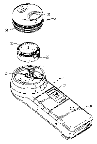
11 Fig. 1 is an exploded perspective view showing the components of the
assembly
12 of the present invention;
13 Fig. 2 is a perspective view of tk~e rotation seat, wherein the rotation is
presented
14 up-side-down so as to clearly show the inner construction of the rotation
seat;
Fig. 3 is a schematic cross sectional view showing the combination of the
1 b rotation seat and the axle of the power means;
17 Fig. 4 is a perspective view showing the appearance of the fingernail
filing
18 assembly of the present invention; and
19 Fig. 5 is a perspective view showing an electrical motor.
j~~''r' TLED D .. Tp'fION OF E PREFEIg~FD $ME30DIMENT
21 l~Vith reference to Fig. 1, it is noted that the motorized fingernail
ftliz~g assembly
22 in accordance with the present invention includes means for providing
power, a rotation
23 seat (2) and a cover (3). The power means may be anything having an ability
to rotate an
24 axle (11) extending out ofthe power means. Ian this embodiment, the power
means (1) is

CA 02509053 2005-05-19
1 provided with a casing (10) and a switch (12) slidably mounted vr~ the
casing (10). The
2 axle (11) is activated to rotate when the switch (12) is slid manually from
an 'off mode
3 to an 'on' mode.
4 With reference to Fig. 2 and still taking Fig. 1 far reference, it is noted
that the
rotation seat {2) has a grinding stone (21) securely mounted on the rotation
seat (2), and
6 escape holes (22) defined in a peripheral wall of the rotation seat (2) to
allow
7 communication between an interior of the rotation seat (2) and the ambient
air. Further,
8 the rotation seat (2) has a hollow mounting collar (23) extending from an
inner face of
9 the mounting seat (2) to correspond to the axle (1 l) of the power means {1)
such that the
axle (I1) of the power means (1) is able to be securely received in the hollow
mounting
11 collar (23).1'he cover (3) has an outer threading {31) formed vn an outer
periphery
12 thereof to correspond to an inner threading (13) formed an an inner
periphery of the
13 power means (1), at least one opening (32) defined through the cover (3) to
provide an
14 access to the grinding stone (2I) such that the user is able to place a
finger on top of the
cover (3) to allow the fingernail to engage with the grinding stone (21) via
the at least
16 one opening (32) whereby floe fingernail is filed.
17 'With reference to Figs. 3 and 4, to combine the components of the
motorized
18 Fingernail filing assembly, the axle (11) of the power means (1) is
inserted into the
19 hollow mounting collar (23) of the rotation seat (2) and then the cover (3)
is connected
to the power means (I) via the combination between the inner threading (13)
and the
21 outer threading (31 ). After the cover (3) is connected to the power means
( 1 ), the
22 rotation seat (2) is retained inside a space defined between the cover (3)
and the power
23 means (1). Thus when the fingernail filing assembly operates, the user is
able to insert a
24 fingernail into the at least one opening (32) to engage with the rotating
grinding stone

CA 02509053 2005-05-19
4
1 (21) to have the fingernail filed. The fingernail dust coming off the
fingernail due to the
2 grinding by the grinding stone (21) is contained in the space between the
power means
3 ( 1) and the cover (3) via the escape holes (22).
4 It is to be understood, however, that even though numerous characteristics
and
advantages of the present irwention have been set forth in the foregoing
description,
6 together with details of the structure and function of the invention, the
disclosure is
7 illustrative only, and changes may be made in detail, especially in matters
of shape, size,
8 and arrangement of parts within the principles of the invention to the full
extent
9 indicated by the broad general meaning of the terms in which the appended
claims are
expressed.

Representative Drawing
A single figure which represents the drawing illustrating the invention.
Administrative Status

2024-08-01:As part of the Next Generation Patents (NGP) transition, the Canadian Patents Database (CPD) now contains a more detailed Event History, which replicates the Event Log of our new back-office solution.

Please note that "Inactive:" events refers to events no longer in use in our new back-office solution.

For a clearer understanding of the status of the application/patent presented on this page, the site Disclaimer , as well as the definitions for Patent , Event History , Maintenance Fee  and Payment History  should be consulted.

Event History

Description Date
Application Not Reinstated by Deadline 2008-05-20
Time Limit for Reversal Expired 2008-05-20
Deemed Abandoned - Failure to Respond to Maintenance Fee Notice 2007-05-22
Application Published (Open to Public Inspection) 2006-11-19
Inactive: Cover page published 2006-11-19
Inactive: First IPC assigned 2005-09-28
Filing Requirements Determined Compliant 2005-07-15
Letter Sent 2005-07-15
Inactive: Filing certificate - RFE (English) 2005-07-15
Application Received - Regular National 2005-07-15
All Requirements for Examination Determined Compliant 2005-05-19
Request for Examination Requirements Determined Compliant 2005-05-19

Abandonment History

Abandonment Date Reason Reinstatement Date
2007-05-22

Fee History

Fee Type Anniversary Year Due Date Paid Date
Application fee - small 2005-05-19
Request for examination - small 2005-05-19
Owners on Record

Note: Records showing the ownership history in alphabetical order.

Current Owners on Record
SHIANN-TORNG CHERN
Past Owners on Record
None
Past Owners that do not appear in the "Owners on Record" listing will appear in other documentation within the application.
Documents

To view selected files, please enter reCAPTCHA code :


To view images, click a link in the Document Description column. To download the documents, select one or more checkboxes in the first column and then click the "Download Selected in PDF format (Zip Archive)" or the "Download Selected as Single PDF" button.

List of published and non-published patent-specific documents on the CPD .

If you have any difficulty accessing content, you can call the Client Service Centre at 1-866-997-1936 or send them an e-mail at CIPO Client Service Centre.


Document
Description 
Date
(yyyy-mm-dd) 
Number of pages   Size of Image (KB) 
Abstract 2005-05-19 1 17
Description 2005-05-19 4 137
Drawings 2005-05-19 5 87
Claims 2005-05-19 1 32
Representative drawing 2006-10-24 1 12
Cover Page 2006-11-03 2 43
Acknowledgement of Request for Examination 2005-07-15 1 175
Filing Certificate (English) 2005-07-15 1 158
Reminder of maintenance fee due 2007-01-22 1 111
Courtesy - Abandonment Letter (Maintenance Fee) 2007-07-17 1 174
Correspondence 2005-07-15 1 34
Correspondence 2007-01-22 1 38
Correspondence 2007-07-17 1 95