Sélection de la langue

Search

Sommaire du brevet 2509053 

Énoncé de désistement de responsabilité concernant l'information provenant de tiers

Une partie des informations de ce site Web a été fournie par des sources externes. Le gouvernement du Canada n'assume aucune responsabilité concernant la précision, l'actualité ou la fiabilité des informations fournies par les sources externes. Les utilisateurs qui désirent employer cette information devraient consulter directement la source des informations. Le contenu fourni par les sources externes n'est pas assujetti aux exigences sur les langues officielles, la protection des renseignements personnels et l'accessibilité.

Disponibilité de l'Abrégé et des Revendications

L'apparition de différences dans le texte et l'image des Revendications et de l'Abrégé dépend du moment auquel le document est publié. Les textes des Revendications et de l'Abrégé sont affichés :

  • lorsque la demande peut être examinée par le public;
  • lorsque le brevet est émis (délivrance).
(12) Demande de brevet: (11) CA 2509053
(54) Titre français: ENSEMBLE MOTORISE DE LIMAGE D'ONGLES
(54) Titre anglais: MOTORIZED FINGERNAIL FILING ASSEMBLY
Statut: Réputée abandonnée et au-delà du délai pour le rétablissement - en attente de la réponse à l’avis de communication rejetée
Données bibliographiques
Abrégés

Abrégé anglais


A fingernail filing assembly includes a power device, a rotation seat having a
hollow
mounting collar extending from an inner face of the rotation seat to
correspond to and to
receive therein the axle and a grinding stone securely mounted an top of the
rotation seat
and a cover threadingly connected to the power device to sandwich therebetween
the
rotation seat with the power device. The cover has at least one opening
defined through
the cover to provide an access to the grinding stone such that a fingernail is
able to
extend into the at least one opening to have the fingernail filed by the
rotating grinding
stone.

Revendications

Note : Les revendications sont présentées dans la langue officielle dans laquelle elles ont été soumises.


5
WHAT IS CLAIMED IS:
1, A fingernail filing assembly comprising:
a power means having an axle rotatably mounted on the power means and
extending oat of the power means;
a rotation seat having a hollow mounting collar extending from an inner face
of
the rotation seat to correspond to and to receive therein the axle and a
grinding stone
securely mounted on top of the rotation seat;
a cover threadingly connected to the power means to sandwich therebetween the
rotation seat with the power means, the cover having at least one opening
defined
through the cover to provide an access to the grinding stone such that a
fingernail is able
to extend into the at least one opening to have the fingernail in abrasive
contact with the
rotating grinding stone.
2. The fingernail fling assembly as claimed in claim 1, wherein the rotation
seat
has multiple escape holes defined in a peripheral wall of the rotation seat to
allow
fingernail dust to escape via the escape holes.
3. The fingernail filing assembly as claimed in claim 2, wherein the power
means has an inner threading and the cover has an outer threading so that
combination
between the inner threading and the outer threading secures engagement between
the
power means and the cover.
4. The fingernail filing assembly as claimed in claim 2, wherein two openings
are defined in the cover.

Description

Note : Les descriptions sont présentées dans la langue officielle dans laquelle elles ont été soumises.

CA 02509053 2005-05-19
1 MOTORIZED FINGERNA,IiL FILING ASSEMBLY
2 BAOK rROLTNr~ OF'(~lN'VENTION
3 1. Field of the Invention
4 The present invention relates to a fingernail fling assembly, and more
particularly to a motorized fingernail filing assembly.
6 2. l7escriptian of Related A.rt
7 When a person wants a manicure as a service, or wishes to da it without the
8 assistance of another, at least clippers and manicure scissors must be
prepared. Once
9 the ~'lngernails have been trimmed by using either the clipper or the
manicure scissors,
an abrasive strip is used to finish off the fiuagernaiIs. That is, the basic
cutting of
11 fingernails requires the clippers and scissors, and the one finishing
further requires
12 the abrasive board, and these three items involve some effort.
13 Furthermore, the waste clippings prove to be a nuisance in that they
sometimes
14 fly away from the scissors ete, which results in unsightly and unsanitary
consequences, and those clippings still can be diffcult to dispose of when
they are
16 collected.
17 To overcome the shortcomings, the present invention tends to provide an
18 improved fingernail filing assembly to mitigate the aforementioned
problems.
19
The primary objective of the present invention is to provide a motorized
2t fingernail filing assembly so that a person is able to accomplish filing
fingernails using
~2 only a single device.
23 In one aspect of the present invention, the motorized fingernail filing
assembly
24 has means for providing power, a rotation seat securely mounted on top of
the power

CA 02509053 2005-05-19
2
1 means to rotate along with an axle extending from the power means, a
grinding stone
2 securely mounted on the rotation seat and a cover threadingly connected to
the power
3 means and having at least one opening defined through the cover to provide
an access to
4 the grinding stone such that the user is able to place the ringer on top of
the cover to
allow the fingernail to protrude to the rotating grinding stone via the at
least one opening
6 whereby the ft~ngernail is filed.
7 Other objects, advantages and novel features of the invention wilt become
more
$ apparent from the following detailed description when taken in conjunction
with the
9 accompanying drawings.
BR~F DE,R~RtPTION OF TES 1~'R_A_ _ GS
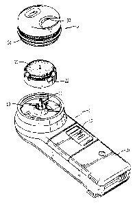
11 Fig. 1 is an exploded perspective view showing the components of the
assembly
12 of the present invention;
13 Fig. 2 is a perspective view of tk~e rotation seat, wherein the rotation is
presented
14 up-side-down so as to clearly show the inner construction of the rotation
seat;
Fig. 3 is a schematic cross sectional view showing the combination of the
1 b rotation seat and the axle of the power means;
17 Fig. 4 is a perspective view showing the appearance of the fingernail
filing
18 assembly of the present invention; and
19 Fig. 5 is a perspective view showing an electrical motor.
j~~''r' TLED D .. Tp'fION OF E PREFEIg~FD $ME30DIMENT
21 l~Vith reference to Fig. 1, it is noted that the motorized fingernail
ftliz~g assembly
22 in accordance with the present invention includes means for providing
power, a rotation
23 seat (2) and a cover (3). The power means may be anything having an ability
to rotate an
24 axle (11) extending out ofthe power means. Ian this embodiment, the power
means (1) is

CA 02509053 2005-05-19
1 provided with a casing (10) and a switch (12) slidably mounted vr~ the
casing (10). The
2 axle (11) is activated to rotate when the switch (12) is slid manually from
an 'off mode
3 to an 'on' mode.
4 With reference to Fig. 2 and still taking Fig. 1 far reference, it is noted
that the
rotation seat {2) has a grinding stone (21) securely mounted on the rotation
seat (2), and
6 escape holes (22) defined in a peripheral wall of the rotation seat (2) to
allow
7 communication between an interior of the rotation seat (2) and the ambient
air. Further,
8 the rotation seat (2) has a hollow mounting collar (23) extending from an
inner face of
9 the mounting seat (2) to correspond to the axle (1 l) of the power means {1)
such that the
axle (I1) of the power means (1) is able to be securely received in the hollow
mounting
11 collar (23).1'he cover (3) has an outer threading {31) formed vn an outer
periphery
12 thereof to correspond to an inner threading (13) formed an an inner
periphery of the
13 power means (1), at least one opening (32) defined through the cover (3) to
provide an
14 access to the grinding stone (2I) such that the user is able to place a
finger on top of the
cover (3) to allow the fingernail to engage with the grinding stone (21) via
the at least
16 one opening (32) whereby floe fingernail is filed.
17 'With reference to Figs. 3 and 4, to combine the components of the
motorized
18 Fingernail filing assembly, the axle (11) of the power means (1) is
inserted into the
19 hollow mounting collar (23) of the rotation seat (2) and then the cover (3)
is connected
to the power means (I) via the combination between the inner threading (13)
and the
21 outer threading (31 ). After the cover (3) is connected to the power means
( 1 ), the
22 rotation seat (2) is retained inside a space defined between the cover (3)
and the power
23 means (1). Thus when the fingernail filing assembly operates, the user is
able to insert a
24 fingernail into the at least one opening (32) to engage with the rotating
grinding stone

CA 02509053 2005-05-19
4
1 (21) to have the fingernail filed. The fingernail dust coming off the
fingernail due to the
2 grinding by the grinding stone (21) is contained in the space between the
power means
3 ( 1) and the cover (3) via the escape holes (22).
4 It is to be understood, however, that even though numerous characteristics
and
advantages of the present irwention have been set forth in the foregoing
description,
6 together with details of the structure and function of the invention, the
disclosure is
7 illustrative only, and changes may be made in detail, especially in matters
of shape, size,
8 and arrangement of parts within the principles of the invention to the full
extent
9 indicated by the broad general meaning of the terms in which the appended
claims are
expressed.

Dessin représentatif
Une figure unique qui représente un dessin illustrant l'invention.
États administratifs

2024-08-01 : Dans le cadre de la transition vers les Brevets de nouvelle génération (BNG), la base de données sur les brevets canadiens (BDBC) contient désormais un Historique d'événement plus détaillé, qui reproduit le Journal des événements de notre nouvelle solution interne.

Veuillez noter que les événements débutant par « Inactive : » se réfèrent à des événements qui ne sont plus utilisés dans notre nouvelle solution interne.

Pour une meilleure compréhension de l'état de la demande ou brevet qui figure sur cette page, la rubrique Mise en garde , et les descriptions de Brevet , Historique d'événement , Taxes périodiques et Historique des paiements devraient être consultées.

Historique d'événement

Description Date
Demande non rétablie avant l'échéance 2008-05-20
Le délai pour l'annulation est expiré 2008-05-20
Réputée abandonnée - omission de répondre à un avis sur les taxes pour le maintien en état 2007-05-22
Demande publiée (accessible au public) 2006-11-19
Inactive : Page couverture publiée 2006-11-19
Inactive : CIB en 1re position 2005-09-28
Exigences de dépôt - jugé conforme 2005-07-15
Lettre envoyée 2005-07-15
Inactive : Certificat de dépôt - RE (Anglais) 2005-07-15
Demande reçue - nationale ordinaire 2005-07-15
Toutes les exigences pour l'examen - jugée conforme 2005-05-19
Exigences pour une requête d'examen - jugée conforme 2005-05-19

Historique d'abandonnement

Date d'abandonnement Raison Date de rétablissement
2007-05-22

Historique des taxes

Type de taxes Anniversaire Échéance Date payée
Taxe pour le dépôt - petite 2005-05-19
Requête d'examen - petite 2005-05-19
Titulaires au dossier

Les titulaires actuels et antérieures au dossier sont affichés en ordre alphabétique.

Titulaires actuels au dossier
SHIANN-TORNG CHERN
Titulaires antérieures au dossier
S.O.
Les propriétaires antérieurs qui ne figurent pas dans la liste des « Propriétaires au dossier » apparaîtront dans d'autres documents au dossier.
Documents

Pour visionner les fichiers sélectionnés, entrer le code reCAPTCHA :


Pour visualiser une image, cliquer sur un lien dans la colonne description du document. Pour télécharger l'image (les images), cliquer l'une ou plusieurs cases à cocher dans la première colonne et ensuite cliquer sur le bouton "Télécharger sélection en format PDF (archive Zip)" ou le bouton "Télécharger sélection (en un fichier PDF fusionné)".

Liste des documents de brevet publiés et non publiés sur la BDBC .

Si vous avez des difficultés à accéder au contenu, veuillez communiquer avec le Centre de services à la clientèle au 1-866-997-1936, ou envoyer un courriel au Centre de service à la clientèle de l'OPIC.


Description du
Document 
Date
(aaaa-mm-jj) 
Nombre de pages   Taille de l'image (Ko) 
Abrégé 2005-05-19 1 17
Description 2005-05-19 4 137
Dessins 2005-05-19 5 87
Revendications 2005-05-19 1 32
Dessin représentatif 2006-10-24 1 12
Page couverture 2006-11-03 2 43
Accusé de réception de la requête d'examen 2005-07-15 1 175
Certificat de dépôt (anglais) 2005-07-15 1 158
Rappel de taxe de maintien due 2007-01-22 1 111
Courtoisie - Lettre d'abandon (taxe de maintien en état) 2007-07-17 1 174
Correspondance 2005-07-15 1 34
Correspondance 2007-01-22 1 38
Correspondance 2007-07-17 1 95