Note: Descriptions are shown in the official language in which they were submitted.
CA 02509277 2005-06-07
Patent Application
ALL TERRAIN LUMBER COLLECTION AND STACKING APPARATUS
FIELD
The present invention relates to an all terrain apparatus for collecting and
stacking lumber
pieces.
BACKGROUND
In laying pipe, such as in gas or oil pipeline, it s conventional that lengths
of pipe are
supported end to end on stacked lumber pieces known as "skids" so that the
pipe lengths
can be held at a required height to be supported and aligned end to end for
welding of the
lengths, prior to feeding of the completed welded length into a trench
adjacent to the
stacks. After the pipe lengths are welded into a continuous length, the pipe
is lifted from
the skids and deposited in a continuous action along its length into the
trench.
At some point, usually after the pipe has been laid into the trench, it is
necessary to collect
the lumber pieces from the skids and to transport them to a new site,
preferably to be used
again, for example at a further location along the pipeline.
The lumber pieces, which are conventionally either four or five feet in length
and six by
four inches in cross section are lifted and handled manually for stacking onto
a transport
container. This manual process is expensive and time consuming, since it
requires a gang
of laborers working hard and commanding high wages. In many cases the stack
has been
disturbed, and the pieces are strewn about, or even compressed in the ground
by the tracks
of passing vehicles, making the work even more labor intensive.
While this step is a relatively minor one in the process of laying the
pipeline, it constitutes
a significant expense and therefore provides a significant opportunity for a
manufacturer
of an effective machine which will carry out this step while eliminating or
reducing the
manual labor involved.
In US patent 5934861 issued August 10'h 1999, which corresponds to Canadian
patent
application no. 2,241,682 published February 1999, discloses an apparatus for
picking up
DMSLegal~053602~0000612043100v5
CA 02509277 2005-06-07
2
pieces of lumber and conveying them to a transport truck. Canadian patent
application no.
2,315,046 published February 3, 2002 discloses an apparatus for picking up,
stacking and
bundling pieces of lumber.
Both of these prior art apparatuses are limited in application, in that they
require smooth,
flat and dry ground conditions in order to pick up lumber pieces from the
ground. Further,
they cannot pick up lumber pieces from a ground surface that is more than 30
cm above or
below the tractor that is powering the apparatus. They are also limited in
that the area in
which lumber can be picked up is restricted to the width of the opening of the
pick up
section of the apparatus.
SUMMARY
The present apparatus uses a grapple to pick up and deposit lumber pieces from
the ground
into a conveyor assembly, which cleans and orients the lumber for deposition
into a
stacking and bundling assembly. The bundled lumber that is prepared by the
stacking and
bundling assembly can be deposited to the ground, or it can be stored in a
storage area on
the apparatus itself, where it may be carried to a secondary location for
transfer to another
vehicle. The grapple may be used to move the bundles of lumber that are
prepared by the
stacking and bundling assembly, either to the ground or to the storage area on
the
apparatus.
One advantage of the apparatus described herein, as compared to prior art
apparatus
disclosed in Canadian patent application no. 2,315,046, is that it does not
have to be
moving in a forward direction, in order to pick up lumber pieces from the
ground.
Therefore it may be used for stationary yard work. Another advantage is that
the
apparatus can pick up and bundle lumber from many different types of uneven
ground
surfaces (e.g., muddy, rocky, wet), or from water. Another advantage is that
it may pick
up lumber over a wide area surrounding the apparatus, for example in front of
or on both
sides of the apparatus, or on either side of the pipeline or the trench in
which the pipeline
has been laid. In one embodiment the apparatus comprises leveling means, so
that it is
able to function on inclines and declines. In one embodiment the apparatus can
store
bundled lumber for transport to a secondary location, avoiding the need to
have a second
vehicle pick up and transport the bundled lumber produced by the apparatus.
DMSL.ega1~053602~00006~2043100v5
CA 02509277 2005-06-07
3
In one aspect, the invention is an apparatus for picking up, stacking and
bundling lumber,
comprising:
(a) a drive means,
(b) a conveyor assembly that comprises a receiving bin and a conveyor,
(c) a stacking assembly operatively connected to the conveyor assembly, and
that comprises an unscrambling hopper, a row conveyor, a stacking bin and a
bundling assembly,
(d) a discharge platform, and
(e) a grapple assembly sized to pick up lumber pieces and deposit the lumber
pieces into the receiving bin.
In one embodiment, the grapple assembly is further sized to pick up a bundle
of lumber
produced by the stacking assembly, for movement to a secondary location. In
another
embodiment, the drive means is a vehicle and the grapple assembly is mounted
to the
vehicle. In another embodiment the conveyor assembly, stacking assembly and
discharge
platform are on a trailer that is pulled by the vehicle. In another embodiment
the grapple
assembly is mounted to the trailer. In another embodiment, the apparatus
further
comprises a storage area. In yet another embodiment, the apparatus further
comprises a
means of raising and lowering the conveyor assembly.
In another aspect, the invention is a method of picking up, stacking and
bundling lumber,
comprising:
(a) providing an apparatus that comprises:
(i) a conveyor assembly that comprises a receiving bin and a conveyor;
(ii) a stacking assembly operatively connected to the conveyor
assembly, and that comprises an unscrambling hopper, a row conveyor, a
stacking bin and a bundling assembly;
(iii) a discharge platform, and
DMSL.ega1~053602~00006~2043100v5
CA 02509277 2005-06-07
(vi) a grapple assembly,
4
(b) picking up loose lumber with the grapple and depositing it into the
receiving bin, and
(c) conveying the loose lumber along the conveyor to t:he stacking assembly,
where the lumber is stacked and bundled into a bundle of lumber and deposited
onto the discharge platform.
The method may further comprise the step of picking up the bundle of lumber
from the
discharge platform with the grapple and transferring it to a secondary
location, such as a
storage area provided on the apparatus.
In yet another aspect, the invention is an apparatus for picking up, stacking
and bundling
lumber, comprising:
(a) a drive vehicle comprising a grapple assembly,
(b) a trailer pulled by the drive vehicle that comprises:
(i) a conveyor assembly further comprising a. receiving bin and a
conveyor,
(ii) a stacking assembly operatively connected to the conveyor
assembly, further comprising an unscrambling hopper, a row conveyor, a
stacking bin and a bundling assembly, and
(iii) a discharge platform,
wherein the grapple assembly comprises a grapple that is sized to pick up
lumber
and a bundle of lumber,
and wherein the grapple assembly is sized to pick up lumber from a ground
surface, to deposit said lumber into the receiving bin, and to pick up a
bundle of
lumber deposited onto the discharge platform.
The apparatus may further comprise a storage area on the trailer, and the
grapple assembly
may further be sized to pick up a bundle of lumber from the discharge platform
and
DMSL,egal\053602\00006\2043100v5
CA 02509277 2005-06-07
deposit the bundle of lumber in the storage area. The apparatus may further
comprise a
mast assembly for raising and lowering the conveyor assembly.
The apparatus may further comprise a means for adjusting the length of the
unscrambling
hopper or the stacking bin. The apparatus may further comprise a means for
adjusting the
5 width of the stacking bin.
BRIEF DESCRIPTION OF THE DRAWINGS
Figure 1 is a top plan view of one embodiment of the apparatus of the
invention.
Figure 2 is a side elevation view of one embodiment of the apparatus of the
invention.
Figure 3 is a side perspective view of one embodiment of the grapple.
Figure 4 is a side elevation view of one embodiment of the grapple.
Figure 5 is a side perspective view of one embodiment of the elevating chain
assembly and
row conveyor.
Figure 6 is a side elevation view of one embodiment of the row conveyor.
Figure 7 is a side perspective view of one embodiment of the unscrambling
hopper and
row conveyor.
Figure 8 is a sectional view taken along line I-I of the apparatus shown in
Figure 1.
Figure 9 A-E is side perspective views of one embodiment of the stacking bin,
bundling
assembly and discharge platform. Figures 9A-D demonstrates the process of
moving the
stack through the bundling assembly to the discharge platform. Figure 9E shows
various
features of the stacking bin.
Figure 10 A-C is side elevation views of an embodiment of the apparatus of
this invention
traveling up a hill with a 27 degree incline (A), on relatively level ground
(B) and down a
hill with a 27 degree decline.
Figure 11A is an end elevation view of an embodiment of the apparatus of the
invention
showing the position of the mast assembly and conveyor assembly relative to
the trailer,
DMSLega1~053602m0006~2043100v5
CA 02509277 2005-06-07
6
when the apparatus is on an incline (C), level ground (B) or decline (A).
Figure 11B is a
side elevation view of an embodiment of the apparatus of the invention showing
the
position of the conveyor assembly relative to the stacking assembly, when the
apparatus is
on an incline (C), level ground (B) or decline (A).
Figure 12 is an end elevation view of an embodiment of the apparatus of the
invention
demonstrating how the mast assembly is positioned, after removal of the
conveyor
assembly, for transport.
Figure 13 is a side elevation view of the bundling assembly and discharge
platform.
DETAILED DESCRIPTION OF PREFERRED EMBODIMENTS
Reference will now be made to Figures 1-13, which show exemplary embodiments
of the
apparatus of the invention.
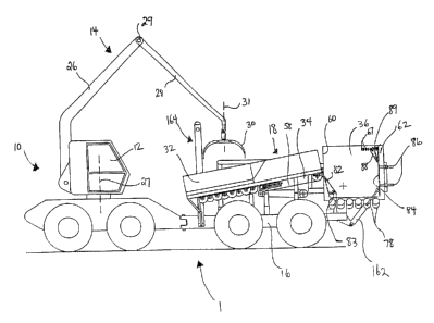
The apparatus 1, as shown in Figure 1 and 2, comprises a drive means 10, a
grapple
assembly generally indicated at 14, a conveyor assembly generally indicated at
18, a
stacking assembly generally indicated at 20, a discharge platform 22 and
optionally, a
storage area 24. The grapple assembly 14 comprises a working arm 26, a grapple
30, and
an optional extension arm 28. The conveyor assembly 18 comprises a receiving
bin 32
and a conveyor 34. The stacking assembly 20 comprises an unscrambling hopper
36, a
row conveyor 38, a stacking bin 40 and a bundling assembly 42.
The apparatus is moved by drive means 10, such as a vehicle (i.e., excavator),
which may
be operated by a driver who may sit in a cab 12. The driver may also operate
grapple
assembly 14 and conveyor assembly 18. The apparatus is used to pick up, stack
and
bundle, lumber or timber. In one embodiment the lumber has been used to make
skids for
supporting a pipeline, but other types of lumber, such as that used in railway
operations,
could be picked up by this apparatus. A rear operator standing near the
stacking assembly
generally at position 43, controls the stacking operation and various other
aspects of the
stacking and bundling process, as will be described in more detail below.
In one embodiment, shown in Figures 1 and 2, conveyor assembly 18, stacking
assembly
20, discharge platform 22 and storage area 24 may be mounted to a trailer or
frame 16 that
DMSLegal~053602~00006~2043100v5
~
CA 02509277 2005-06-07
7
may be attached to and pulled by drive means 10. In another embodiment, drive
means
10, conveyor assembly 18, stacking assembly 20, discharge platform 22 and
optional
storage area 24 may be of unitary construction (t.e., the drive means may not
be a separate
entity from the remainder of the apparatus).
The grapple assembly 14 comprises working arm 26 and grapple, 30, and
optionally an
extension arm 28, the movement of which may be controlled by hydraulic
cylinders, as is
known in the art. Working arm 26 may be pivotally mounted to drive means 10 in
such a
manner that it may be capable of rotating vertically through a range of 360
degrees. In an
alternative embodiment, working arm 26 may be mounted to trailer 16 in such a
manner
that it may be capable of rotating vertically through a range of 360 degrees.
The driver is
able to view grapple 30 in all of its orientations, in order to control the
picking up of
lumber pieces 44.
In one embodiment, shown in Figure 2, working arm 26 may be mounted onto cab
12,
which may be pivotally mounted to drive means 10. Cab 12 and therefore working
arm
26, may rotate vertically around axis 27 through a range of 360 degrees
rotation.
Extension arm 28 may be pivotally mounted and extend between working arm 26
and
grapple 30. Grapple 30 may be capable of rotating vertically around axis 31
through a
range of 360 degrees and therefore may be rotated fully to pick up lumber
pieces 44,
regardless of the orientation of the lumber on the ground. In another
embodiment, grapple
30 may be attached to working arm 26 at end 29, and may be able to rotate
vertically
through a range of 360 degrees.
Grapple 30 may be used to grasp one, two or several pieces of lumber 44. As
shown in
Figures 3 and 4, grapple 30 has two grapple arms 48, each of which may be
curved. The
curvature causes loose lumber pieces to slide down into the grasp of the
grapple as the
grapple is being closed, to be carried therein. The grapple arms may also
pivot upwards
towards top section 50, to hold the lumber pieces between the arms 48, or
between the top
section 50 and grapple arms 48.
Grapple 30 may also be used to pick up a bundle 46 of lumber, which may in
some
embodiments be rectangular (e.g., square) in cross section. To this end, the
curvature of
each of the grapple arms 48 may taper gently from the tip 52 to pivot point
54, where there
DMSLcga1~053602~00006~2043100v5
CA 02509277 2005-06-07
8
may then be a sharp turn towards top section 50. Top section 50 may be sized
to
accommodate the full width of a side of the bundle of lumber that is to be
picked up, and
may be relatively flat. This enables top section 50 of grapple 30 to engage
the full side of
the bundle 46 of lumber. The grapple arms 48 may then close around the bundle
to
squeeze the bundle from the bottom and push it up against top section 50. By
gripping the
bundle 46 in this way, the corner edges of the bundle and the sides of the
bundle may not
be distorted, and the shape of the bundle of lumber may be maintained. Grapple
30 may
be opened and closed using a hydraulic cylinder assembly, as is known in the
art.
The conveyor assembly 18 receives the lumber pieces from the grapple and
transports the
pieces to unscrambling hopper 36. The conveyor assembly comprises receiving
bin 32 to
receive the lumber pieces that are deposited therein by grapple 30 and
conveyor 34, which
transports the lumber pieces to unscrambling hopper 36, as best seen in Figure
1. In one
embodiment, receiving bin 32 may comprise a series of rollers 56 along its
bottom. These
rollers may each comprise a shaft and a plurality of disks- i.e., they may be
"knobbed".
Knobbed rollers 56 remove and filter mud and other debris from the lumber
pieces.
Conveyor 34 conveys lumber pieces from receiving bin 32 to unscrambling hopper
36.
Conveyor 34 may also function to orient the lumber pieces, because it may be
narrower in
width than the length of the lumber pieces being conveyed, and therefore the
lumber
pieces would generally be oriented longitudinal of the conveyor 34 before
deposition into
unscrambling hopper 36. In one embodiment conveyor 34 may comprise a conveyor
belt
58 mounted on a plurality of rollers (not shown) so that an upper run of the
belt carries the
lumber pieces towards unscrambling hopper 36. In another embodiment conveyor
34 may
comprise a series of rollers, in addition to the rollers 56 along the bottom
of bin 32, that
transport lumber pieces from bin 32 into hopper 36. In yet another embodiment,
these
additional rollers may be knobbed, for further cleaning of the lumber pieces.
Conveyor 34
may be a part of, or integral to, bin 32.
The lumber pieces are discharged from conveyor 34 into unscrambling hopper 36,
which
is the first component of stacking assembly 20. Stacking assembly 20 functions
to
assemble the loose lumber pieces into a stack of predetermined shape and size,
and to
bundle the pieces of that stack securely together. Stacking assembly 20 need
not be
mounted in a subframe.
DMSLegal\053602\00006\2043100v5
CA 02509277 2005-06-07
9
Unscrambling hopper 36 functions to receive the scrambled lumber pieces from
conveyor
34, and to orient them all into the same direction, for formation of the
stack.
Unscrambling hopper 36 comprises a front wall 60, a back wall 62 and two side
walls 64
and 66 that form at their base an apex 68 longitudinal of unscrambling hopper
36 and thus
longitudinal of conveyor 34. Side wall 64 may be inclined and may comprise an
elevating
chain assembly 70 that may be made of three parts, a center chain '72 and two
side chains
74.
At apex 68 may be a roller assembly 76 comprising a plurality of unscrambling
rollers 78
that may be spaced apart to permit debris to fall therebetween onto the ground
surface.
Unscrambling rollers 78 may be oriented at approximately right angles to the
direction
from which the lumber is received (i.e., approximately parallel to the front
and back walls
60 and 62), and they may be sloped so that the ends closest to side wall 64
may be lower
than the ends closest to side wall 66. Rollers 78 rotate in unison and in the
same direction,
which rotation may be controlled by the rear operator, using a variable
hydraulic valve. In
a preferred embodiment, rollers 78 rotate in a direction that causes the
lumber pieces to be
moved towards back wall 62. The rotation and sloping of the unscrambling
rollers 78
displaces lumber pieces 44 towards elevating chain assembly 70, and in a
preferred
embodiment towards back wall 62. Spiral flighting 80 on one or more of the
unscrambling rollers 78 may also be used, to facilitate the movement of lumber
pieces 44
towards elevating chain assembly 70.
The roller assembly 76 may be lowered by the driver or rear operator, for
example by
unlatching the assembly and activating one or more hydraulic cylinders, to
lower the roller
assembly. Figure 8 shows the roller assembly 76 at lowered position 79 (which
is a
partially opened position). This will permit, for example, the removal of
large rocks or
debris from unscrambling hopper 36.
Front wall 60 may further comprise an additional panel 82 that enables the
driver or rear
operator to make adjustments to vary the length of the apex 68, as shown in
Figure 2. The
top edge of panel 82 may be attached to front wall 60, for example to a
slotted track, to
permit the top edge to slide vertically when the bottom edge of panel 82 is
moved towards
and away from back wall 62. Arrow 83 in Figure 2 shows how the bottom edge of
panel
82 may be moved towards and away from front wall 60. At the battom edge of
panel 82,
DMSLega1~053602~0000612043100v5
CA 02509277 2005-06-07
tubular supports may be used to secure the bottom edge in a selected position.
This panel
feature facilitates the use of unscrambling hopper 36 with lumber pieces of
varying
lengths- for example 4 feet or 5 feet in length.
Disposed inside back wall 62 may be an adjustable panel 84 that may be moved
towards
5 and away from front wall 60, as seen in Figure 2. The position of panel 84
may be
determined by adjustment, in increments, of telescoping tubular supports 86
mounted to
stationary back wall 62. This permits the driver or rear operator to adjust
the length of
apex 68 or hopper 36, to facilitate use with lumber pieces of varying lengths-
for example
4 feet or 5 feet in length.
10 Supports 86 may be independently adjustable. Therefore, panel 84 may be
adjusted to tilt
from top to bottom, so that the top edge of the panel may be closer to front
wall 60 than
the bottom edge of the panel. By tilting panel 84 in this way the lumber
pieces, as they are
raised upwards by elevating chain assembly 70, may be forced flush at one end
for
bundling. When combined with a preferred embodiment, mentioned above, in which
rollers 78 rotate in a direction that causes the lumber pieces to be moved
towards back
wall 62, this feature eliminates the need for an end alignment belt to align
the lumber
pieces in the stack.
Panel 84 may also be adjusted to tilt from side to side, so that one side edge
may be closer
to front wall 60 than the other side edge, more specifically, so that the edge
running along
side wall 64 may be further from front wall 60 than the edge running along
side wall 66.
By tilting panel 84 in this way, lumber pieces 44 may move with less friction
towards
elevating chain assembly 70, located on side wall 64.
The top portion of adjustable panel 84, or of back wall 62, may comprise an
additional
plate 88 that may be attached to panel 84 or to back wall 62, at the bottom
edge, for
example with a hinge or by a slotted track. Thus, the top edge of plate 88 may
be moved
toward and away from back wall 62. The top edge of plate 88 may be secured by
a
horizontal sliding and locking pin assembly that inserts into spaced vertical
slots 67 on
wall 66. Arrow 89 in Figure 2 shows how the top edge of plate 88 may be moved
towards
and away from back wall 86. When plate 88 is in a lowered position, as shown
in Figure
2, the alignment of lumber pieces onto elevating chain assembly 70 may be
assisted by
DMSLegal\053602~0000612043100v5
CA 02509277 2005-06-07
11
causing a piece of lumber that may be vertically oriented at the back wall 62,
when it
contacts plate 88, to be forced to fall back into the unscrambling hopper 36
in a horizontal
orientation.
Elevating chain assembly 70 comprises, in this embodiment, center chain 72 and
two side
chains 74, one on either side of the center chain 72. A plurality of
substantially horizontal
abutment bars 90 project outwardly, in order to engage lumber pieces 44. The
elevating
chain assembly and abutment bars preferably extend across the entire width of
side wall
64 rather than only part of side wall 64 as known in the prior art, and
therefore debris build
up in the bottom of unscrambling hopper 36 may be avoided. The abutment bars
also
facilitate unscrambling of lumber pieces as they are received in unscrambling
hopper 36,
as lumber pieces that become positioned vertically in the unscrambling bin may
be
dislodged by the abutment bars. As is apparent, elevating chain assembly 70
may also be
made of one or two elevating chains, or more than three elevating chains. The
same
advantages (i.e., avoiding build up of debris and dislodging lumber pieces)
can be
achieved using any assembly of elevating chains wherein the abutment bars
extend
substantially from side to side of wall 64.
Elevating chain assembly drive sprockets 92 may be mounted on an upper shaft
94 and
idler sprockets 96 may be mounted on shaft 98, with chains 100 carried
thereon. As shafts
94 and 98 rotate, lumber pieces in unscrambling hopper 36 are engaged by
abutment bars
90, lifted upwards along inclined side wall 64 over the top edge of the side
wall and
deposited onto row conveyor 38.
Row conveyor 38 functions to assemble a row of lumber pieces 44 and to
transfer that row
into stacking bin 40, to form a stack of lumber pieces. Row conveyor 38 may
comprise
idler sprockets 102, drive sprockets 104 and chains 106. Idler sprockets 102
may be
mounted on upper shaft 94. The use of upper shaft 94 with both elevating chain
assembly
drive sprockets 92 and idler sprockets 102 provides for a smooth transition of
lumber
pieces 44 from the elevating chain assembly 70 to the row conveyor 38. The
lumber
pieces may be deposited onto chains 106, and may be moved on chains 106
towards
stacking bin 40. Row conveyor 38 may additionally comprise an adjustable
alignment
fence 108, to help ensure that the ends of the lumber pieces are flush with
one another for
bundling.
DMSL.ega1~053602~00006~2043100v5
CA 02509277 2005-06-07
12
Lumber pieces 44 are fed up the elevating chain assembly 70 generally side by
side onto
conveyor chains 106. If more than one lumber piece is carried on any
particular abutment
bar 90, the pieces may end up on top of one another on the row conveyor and
this problem
may be overcome manually by the rear operator standing on the apparatus near
the row
conveyor 38, generally at area 43, to ensure that the stacking process
proceeds effectively.
Lumber pieces 44 may be fed along row conveyor 38 over top of a pair of
lifting arms
110, which may normally be positioned below the level of chains 106 (in "home
position"), so that lumber pieces 44 will clear rear dog 115 as they move on
the row
conveyor. The lumber pieces progress towards stacking bin 40 until they abut
stops 112,
which halt the forward movement of the lumber pieces. The pieces that follow
back up
against the previously stopped pieces to form a row of lumber pieces arranged
side-by-side
and extending back towards unscrambling hopper 36. When a lumber piece is
positioned
and stopped overtop of sensor 114, the approximate location of which is shown
in Figure
6, lifting arms 110 may be lifted up by an actuating mechanism 111, activated
for example
by a hydraulic cylinder, that simultaneously lowers stops 112. The lifting
arms 110 lift up
the row of lumber and rear dog 115 on each of the arms engages the rearmost
lumber piece
of the accumulated row. The row is carried forward on a carriage system 116
driven by
chains 118, to bundle elevator in stacking bin 40, which may comprise
horizontal spaced
supports 122 mounted onto a carriage 123, that may be an independent roller
assembly
that moves vertically in a track (not shown). When lifting arms 110 are
extended over the
horizontal spaced supports, actuating mechanism 111 retracts, thus lowering
arms 110 to
home position and simultaneously raising stops 112. The lumber pieces abut end
120
(Figure 5), as the lifting arms 110 being to retract towards hopper 36, and
may thus be
deposited onto supports 122.
The bundle elevator may already have one or more rows of lumber loaded
thereon, and/or
the rear operator may have manually adjusted a tier of lumber in order to
later assist with
the handling and transfer of bundle 46, for example with a forklift. Figure 9A-
D shows a
stack of lumber in which lumber in the second from bottom tier has been
reoriented
manually to facilitate future movement and storage of bundle 46. The stacking
of
additional rows of lumber continues until horizontal spaced supports 122 are
lowered to a
point where they are below stacking rollers 124, thus leaving the stack of
lumber sitting on
DMSLega1~053602~00006~20431()Ov5
CA 02509277 2005-06-07
13
the stacking rollers 124 at the bottom of the stacking bin 40. The rollers 124
may then be
driven by a chain 125, connected across chain wheels 119, so as to forward the
stack into
bundling assembly 42.
Stacking bin 40 assembles the rows of lumber pieces into a stack and transmits
that stack
to bundling assembly 42. The stacking bin has a front 126, a back 128 and
sides 130 and
132. Rollers 134 extend vertically on the front of the stacking bin. In one
embodiment,
rollers 134 extend from the ends of rollers 124 and may be driven by a gear
assembly from
the end of rollers 124. These rollers reduce the probability that the stack of
lumber pieces
will snag the stacking bin 40, as the bundle moves horizontally into bundling
assembly 42.
Several other features of stacking bin 40 represent improvements over the
stacking bin
disclosed in CA patent application no. 2,315,046. Back 128 may comprise a
plate 127 that
may be adjustable to move substantially horizontally towards and away from
front 126, to
accommodate lumber of varying widths. For example, a standard width of lumber
is six
inches, however this width may be more or less than six inches. If plate 127
does not fit
snugly up against the lumber stack, the outer lumber pieces 44 may fall into
the gap
between the wall and the stack, and therefore distort the shape of the stack
before it moves
horizontally into bundling assembly 42. The position of plate 127 may be
determined by
adjustment, in increments, for example by a threaded rod inside tubular
supports 129
mounted to the frame of stacking bin 40.
Plate 127 may also be hinged at the bottom to allow the wall to fold inwards
and
downwards, which may be accomplished, for example, with hydraulic cylinders.
This
feature may be used during transport of the apparatus, as the stacking bin and
bundling
assembly may be rotated 180 degrees for transport, to rest over top of row
conveyor 38.
Side 130 may comprise a plate 136 that may be adjustable to move towards and
away
from side 130, in order that the stacking bin 40 may accommodate lumber pieces
of
varying length, such as 4 feet or 5 feet. In one embodiment plate 1.36 may be
adjusted by
six inches. Adjustment of plate 136 may be accomplished by a wheel and pulley
mechanism 138, as shown in Figure 9.
Bundling assembly 42 comprises a substantially rectangular frame 140 sized to
receive the
stack of lumber therein, even in the event that the stack may be slightly
loose or expanded
DMSLega1~05360210000612043100v5
. CA 02509277 2005-06-07
14
in dimension by distorted or slightly twisted pieces. The bottom rail 142 of
frame 140
may comprise a horizontal drive roller 144 disposed in the frame, to reduce
the probability
that the bottom row of lumber in the stack will become snagged by bottom rail
142 as it is
advanced through the opening in the frame, and thereby hinder bundling of the
stack.
Bundling of the stack occurs essentially as described in CA patent application
no.
2,315,046, which is incorporated by reference herein, and which is best shown
in Figures
8 and 9. In addition to bottom rail 142, frame 140 comprises a top rail 145
and two side
rails 146 and 148. A first clamping arm 147 may be disposed substantially
parallel to a
first rail, preferably retracted into a slot of the rail. The first clamping
arm is preferably
retracted into top rail 145. A second clamping arm 149 may be disposed
substantially
parallel to another rail that is substantially perpendicular to the first
rail, preferably
retracted into a slot in the rail. The second clamping arm is preferably
retracted into side
rail 146. Each of these clamping arms may be actuated with a pair of hydraulic
cylinders
150 or 152 (see Figure 8), into engagement with a surface of the stack of
lumber, to
thereby squeeze the lumber pieces within the stack so that they may be pressed
together to
eliminate spaces between the pieces and the ensure that they are fully aligned
and in
contact.
With the stack thus clamped, a length of strapping material 154 may be used to
hold the
lumber pieces in the stack securely together. Strapping material 154 may be
carried
around the stack by a chain 156, which extends around four sprockets 158 each
mounted
at a corner of frame 140. One of the sprockets may be driven and the others
may be idlers,
so that the chain can be rotated around the frame so as to complete a single
loop around
the frame. The chain 156 and sprockets 158 may be mounted on either the front
or rear
face of frame 140, so that they are alongside the frame and do not interfere
with the
movement of the stack through the frame 140. The chain carries, at one end, a
gripping
member (not shown) around which an end of strapping material 1.54 can be
engaged so
that the end may be carried with the chain as it moves around the frame, thus
carrying the
end completely around the stack to a position where it may be crimped manually
with
another end of the strapping material. The two ends of the loop of strapping
material 154
may be crimped by a manually operable strapping system known in the art. For
example,
a crimping head that acts to tighten the loop and simultaneously crimp or lock
the two
DMSL.egal\053602\00006\2043100v5
CA 02509277 2005-06-07
ends of the loop together so the strapping is maintained fixed around the
stack, may be
used.
Clamping arms may then be released and the bundle 46 may then bc: advanced by
stacking
rollers 124 and/or discharge platform 22, and positioned to apply one more
strap
5 thereabout. When the desired number of straps is applied, the stacking
rollers 124 and/or
discharge platform 22, may be activated to move the stack from its position in
bundling
assembly 42 onto discharge platform 22.
Discharge platform 22 is an area where bundle 46 may be deposited, so that it
can be
picked up by grapple assembly 14. Alternatively, discharge platform may be
designed to
10 deposit bundle 46 directly onto the ground. In one embodiment, the
discharge platform
includes a conveyor belt 160 and rollers 161a and 161b to advance bundle 46
out of the
bundling assembly 42 on an upper run of the belt. Grapple assembly 14 may then
pick up
bundle 46 and deposit it in storage area 24, onto another vehicle nearby or
onto the
ground.
15 Discharge platform 22 may be fixed to trailer 16 with shear bolts 135 which
may be
attached to support frame 137 that rests on a bracing member 139, as shown in
Figure 13.
The shear bolt is a safety mechanism to protect the stacking assembly from
damage that
might result from operator error when attempting to lift bundle 46 with
grapple assembly
14. If, for example, the entire weight of the grapple is placed onto platform
22, shear bolts
135 will break and platform 22 will pivot at point 141, and swing downwards.
Storage area 24 may be sized to accommodate several bundles 46 of lumber,
beside one
another and/or stacked on top of one another. Bundles of lumber may be
deposited in
storage area 24 and transported to a second location, avoiding the need for a
second
vehicle, such as a Skidsteer, to follow the apparatus and pick up the bundles.
In one
embodiment the apparatus can carry 10 bundles of lumber. The bundles of lumber
thus
stored may be picked up by the grapple assembly 30 and moved to a secondary
location,
such as a storage yard or a second vehicle.
The apparatus of the present invention may be used on terrain that is not
level, as indicated
in Figure l0A-C. Therefore, in some embodiments, also provided is a means of
maintaining stacking assembly 20 level which may be coupled with a means of
leveling
DMSLeg~1~053602~00006~2043100v5
CA 02509277 2005-06-07
16
conveyor assembly 18, in response to varying terrains, so that it will
efficiently deposit
lumber pieces into unscrambling hopper 36. This feature, in addition to the
use of a
grapple, provides even greater flexibility with regard to terrain, than the
prior art device
disclosed in Canadian patent application no. 2,315,046, or the use of a
grapple alone.
Figure 10 demonstrates the relative movement of conveyor assembly 18 and
stacking
assembly 20, when an embodiment of the apparatus comprising both a means for
leveling
the conveyor assembly 18 and stacking assembly 20, is proceeding up a hill
with an
incline of 27 degrees (l0A), on a level surface (lOB), and down a hill with a
decline of 27
degrees (lOC). As noted, stacking assembly 20 remains relatively level in all
situations.
This may be accomplished by pivoting stacking assembly 20 about pivot point
163 by
actuating hydraulic cylinders 162. As stacking assembly 20 pivots about 163,
the end of
conveyor assembly 18 may also pivot about pivot point 165.
The apparatus may also comprise a mast assembly 164, to raise and lower the
conveyor
assembly 18, to accommodate for the slope of the land on which the apparatus
is being
used. Therefore, conveyor assembly 18 may be moved up or down along mast
assembly
164, which may comprise an inner mast 166 and an outer mast 168, each of which
may
comprise a hydraulic cylinder disposed therein to provide means of moving the
mast
vertically. Figures 11A and B shows the position of outer mast 168 and inner
mast 166 at
three different positions or heights, A, B and C, of conveyor assembly 18,
corresponding
to Figure lOC, Figure lOB and Figure 10A, respectively.
Inner mast 166 may be mounted relatively perpendicular to the chassis of the
trailer 16, as
shown in Figure 11A, and may be pivotally connected to outer mast 168 at pivot
point
170. Conveyor assembly 18 may be attached to outer mast 168 at pivot point
172, and
moves up and down with outer mast 168. Inner mast 166 telescopes upwardly to
achieve
position A in Figure lOC. Outer mast 168 pivots about point 170 on inner mast
166, as
conveyor assembly 18 moves up and down pivoting about point 172. The angular
displacement of outer mast 168 relative to inner mast 166 can best be seen in
Figure 11B
at arrows 174. As the mast assembly 164 is raised and lowered, the. other end
of conveyor
assembly 18 may also pivot about pivot point 165.
In preparation for transport of the apparatus, conveyor assembly 18 may be
removed from
mast 168, and mast assembly 164 may be lowered into a prone position for
transport, by
DMSLegal~053602~00006~2043100v5
CA 02509277 2005-06-07
17
pivoting about point 173, in the direction of arrow 175, as shown in Figure
12.
Additionally, unscrambling hopper 36 may be pivoted about shaft 94 by 180
degrees, to
rest on top of row conveyor 38. At the other end of row conveyor 38, plate 127
of
stacking bin 40 may be lowered onto stacking rollers 124, and discharge
platform 22 may
be pivoted upwards by about 90 degrees about the shaft 169 of roller 161a, and
latched to
bundling assembly 42 (see Figure 13). The stacking bin 40, bundling assembly
42 and
discharge platform may then be rotated 180 degrees about axis 176 (see Figure
9E), to rest
on top of the unscrambling hopper 38. The stacking bin and attached bundling
assembly/discharge platform may be lifted and flipped over by using grapple
assembly 14
to grasp a sling that may be connected to a lifting lug 178, shown in Figure
13. A similar
lug/sling assembly may be used to lift and flip over unscrambling hopper 36.
In this
manner, the width of the apparatus may be reduced to facilitate transport.
The driver of drive means 10, therefore, preferably controls the picking up
and feeding of
lumber pieces 44 into conveyor assembly 18, the conveyor assembly 18, and the
removal
of bundle 46 from discharge platform 22. The rear operator standing near the
stacking
assembly 20 preferably controls the stacking action by controlling the feeding
of the row
of lumber pieces, ensuring that the pieces are properly oriented and carried
onto the bundle
elevator, and controlling the feeding of the bundling through the bundling
assembly and
bundling thereof.
Having thus described apparatus 1 of the present invention, a method of
picking up and
bundling lumber pieces 44, will now be described. A driver, who preferably
also controls
the drive means 10 of the apparatus, operates grapple assembly 14, to pick up
one or more
pieces of lumber 44 from the ground. The lumber piece or pieces are deposited
into
receiving bin 32 by positioning grapple 30 above the receiving bin, and
opening grapple
arms 48 to drop the lumber pieces into the bin. Rollers 56 turn, to move the
lumber pieces
towards conveyor 34, which transports the lumber pieces into unscrambling
hopper 36. In
unscrambling hopper 36 the elevating chain assembly sequentially lifts the
lumber pieces
44 up and deposits them one at a time onto row conveyor 38. On row conveyor 38
the
lumber pieces 44 are assembled into rows, and the rows are assembled one on
top of
another into a stack of lumber, in stacking bin 40. The stack may then be
moved into
bundling assembly 42, where it is bundled into a bundle 46, and deposited onto
discharge
DMSLega11053602~00006~2043100v5
~
~ CA 02509277 2005-06-07
18
platform 22. A rear operator, preferably standing near the stacking assembly
ensures that
the stacking and bundling process proceeds smoothly.
Bundle 46 may then be picked up by grapple assembly 14 and deposited in
storage area
24, onto a waiting vehicle, or onto the ground. Alternatively, the discharge
platform 22
may deposit the bundle directly onto the ground.
While the apparatus has been described in conjunction with the disclosed
embodiments, it
will be understood that the apparatus is not intended to be limited to these
embodiments.
On the contrary, the apparatus is intended to cover alternatives,
modifications and
equivalents, which may be included within the spirit and scope of the
invention as defined
by the appended claims. Various modifications will remain readily apparent to
those
skilled in the art.
DMSLegat~053602~0006~2043100v5