Language selection

Search

Patent 2509315 Summary

Third-party information liability

Some of the information on this Web page has been provided by external sources. The Government of Canada is not responsible for the accuracy, reliability or currency of the information supplied by external sources. Users wishing to rely upon this information should consult directly with the source of the information. Content provided by external sources is not subject to official languages, privacy and accessibility requirements.

Claims and Abstract availability

Any discrepancies in the text and image of the Claims and Abstract are due to differing posting times. Text of the Claims and Abstract are posted:

  • At the time the application is open to public inspection;
  • At the time of issue of the patent (grant).
(12) Patent: (11) CA 2509315
(54) English Title: PROCESS FOR THE CONTINUOUS PRODUCTION OF LONGITUDINALLY WELDED METAL TUBES
(54) French Title: PROCEDE DE PRODUCTION CONTINUE DE TUBES METALLIQUES A SOUDAGE LONGITUDINAL
Status: Deemed expired
Bibliographic Data
(51) International Patent Classification (IPC):
  • B23K 9/16 (2006.01)
  • B21C 37/08 (2006.01)
  • F16L 9/17 (2006.01)
(72) Inventors :
  • FROHNE, CHRISTIAN (Germany)
  • HOFFMANN, ERNST (Germany)
  • BRUENN, RAINER (Germany)
(73) Owners :
  • NEXANS (France)
(71) Applicants :
  • NEXANS (France)
(74) Agent: ROBIC
(74) Associate agent:
(45) Issued: 2011-11-29
(22) Filed Date: 2005-06-08
(41) Open to Public Inspection: 2005-12-09
Examination requested: 2009-05-28
Availability of licence: N/A
(25) Language of filing: English

Patent Cooperation Treaty (PCT): No

(30) Application Priority Data:
Application No. Country/Territory Date
04 291 437.4 European Patent Office (EPO) 2004-06-09

Abstracts

English Abstract

A process for the continuous production of longitudinally welded metal tubes is described, wherein a metal strip (1) is drawn from a strip supply and gradually shaped into a slit tube in a shaping station (2), the slit tube is welded in a welding system (4) along the edges of the strip, and the welded tube (6) is extracted by an extraction device (5). The welding system (4) is a protective gas arc welding system with several electrodes supplied by separate sources (4c, 4d) of welding current. The electrodes are arranged in succession in the direction of production. The welding system (4) has two welding devices (4a, 4b), whose electrode tips are directed at a common welding point. Only one of the welding devices (4a, 4b) is in operation at any given time, while the other welding device is in a standby position. When an electrode change becomes necessary, the arc of the welding device in the standby position is first struck by means of an auxiliary arc. The welding current intensity of the welding device presently in operation is then reduced, while the welding current intensity of the welding device in the standby position is simultaneously increased.


French Abstract

La présente divulgation décrit la production continue de tubes métalliques à soudage longitudinal. Un ruban métallique (1) est étiré à partir d'un approvisionnement de rubans, et il prend progressivement la forme d'un tube fendu dans un poste de façonnage (2). Le tube fendu est soudé dans un dispositif de soudage (4) le long du ruban, et le tube soudé (6) est extrait par un extracteur (5). Le dispositif de soudage (4) est un dispositif de soudage à l'arc sous gaz protecteur avec plusieurs électrodes alimentées par des sources distinctes (4c, 4d) du courant de soudage. Ces électrodes sont disposées successivement dans le sens de la chaîne de production. Le dispositif de soudage (4) comprend deux ensembles de soudage (4a, 4b), dont les pointes des électrodes sont orientées vers un point de soudage commun. Seulement un des ensembles de soudage (4a, 4b) fonctionne sans arrêt, tandis que l'autre ensemble de soudage est en attente. Lorsqu'il est nécessaire de changer d'électrode, l'arc de l'ensemble de soudage en attente est d'abord frappé au moyen d'un arc auxiliaire. L'intensité du courant de soudage de l'ensemble de soudage en cours de fonctionnement est alors réduite, tandis que l'intensité du courant de soudage de l'ensemble de soudage en attente augmente simultanément.

Claims

Note: Claims are shown in the official language in which they were submitted.


WHAT IS CLAIMED IS:

1. Process for the continuous production of longitudinally welded metal tubes,

wherein a metal strip is drawn from a strip supply and gradually shaped into a
slit
tube in a shaping station, the slit tube is welded in a welding system along
the edges
of the strip, and the welded tube is extracted by an extraction device, and
wherein
the welding system is a protective gas arc welding system with several
electrodes
supplied by separate sources of welding current, and the electrodes are
arranged in
succession in the direction of production, characterized by the fact that the
welding
system has two welding devices, whose electrode tips are directed at a common
welding point; that only one of the welding devices is in operation at any
given time,
while the other welding device is in a standby position; that when an
electrode
change becomes necessary, the arc of the welding device in the standby
position is
first struck by means of an auxiliary arc; and that the welding current
intensity of the
welding device presently in operation is then reduced, while the welding
current
intensity of the welding device in the standby position is simultaneously
increased.

2. Process in accordance with claim 1, characterized by the fact that an
electrode
is replaced by pulling it up and out of the welding device and pushing a new
electrode down and into the welding device.

3. Process in accordance with claims 1 or 2, in which the last stage of the
shaping station is a shaping ring that guides the slit tube, characterized by
the fact
that the welding device adjacent to the shaping ring is arranged vertically,
and the
second welding device, which is arranged after the first welding device in the

direction of travel of the tube, is arranged at an angle of inclination to the
longitudinal
axis of the metal tube of preferably 30-85°.

6

Description

Note: Descriptions are shown in the official language in which they were submitted.


CA 02509315 2011-03-22

PROCESS FOR THE CONTINUOUS PRODUCTION OF LONGITUDINALLY
WELDED METAL TUBES

The invention concerns a process for the continous production of
longitudinally
welded metal tubes.

Various welding processes for the continuous production of longitudinally
welded tubes
are known.

Processes that are used include not only the high-frequency resistance welding
or

induction welding process but also the arc welding process (GTAW welding
process) and the
laser beam welding process. The laser beam welding process in particular has
become
increasingly important in recent years. Disadvantages of the laser beam
welding process are the
high capital costs and operating costs and the fact that the welding of metals
with a bright
surface, e.g., copper, causes problems, since a large portion of the laser
energy is reflected by the
bright metallic surface and thus is not available for the welding process. In
addition, special
precautions must be taken to protect personnel from misdirected laser beams.

The high-frequency welding process is characterized by high production rates,
but the
weld seam leaves much to be desired, so that high-frequency-welded metal tubes
are unsuitable
for encasing plastic tubes or electrical cables.

DE 22 56 851 A describes a system for welding thin plates passing under a
stationary
welding head, especially for welding the longitudinal edges of a metal strip
that has been shaped
into a tube. The welding head of this system has three nonconsumable
electrodes that are
arranged in succession in the direction of the weld seam and supplied by
separate current

1


CA 02509315 2011-03-22

sources. The use of three electrodes serves to increase the welding travel
speed, i.e., all three
electrodes participate in the welding operation. If one of the electrodes
becomes worn out,-the
welding operation must be interrupted, with the result that the production
process must be
stopped and started up again or that, in the case of a continuous operation,
the longitudinal seam
is not welded over a certain length.

The service life of an electrode in the case of are welding under a protective
gas depends
on the degree of contamination of the strip material that is used. In
practice, lengths of up to

1,000 m can be produced in the case of the welding of aluminum strip.

The objective of the invention is to specify a process for producing
longitudinally welded
metal tubes with an arc welding system that makes it possible to produce long
lengths without
interruption of the welding operation.
In accordance with an aspect of the invention, the object is achieved with a
process for the continuous production of longitudinally welded metal tubes,
wherein a
metal strip is drawn from a strip supply and gradually shaped into a slit tube
in a
shaping station, the slit tube is welded in a welding system along the edges
of the
strip, and the welded tube is extracted by an extraction device, and wherein
the
welding system is a protective gas arc welding system with several electrodes
supplied by separate sources of welding current, and the electrodes are
arranged in
succession in the direction of production, characterized by the fact that the
welding
system has two welding devices, whose electrode tips are directed at a common
welding point; that only one of the welding devices is in operation at any
given time,
while the other welding device is in a standby position; that when an
electrode
change becomes necessary, the arc of the welding device in the standby
position is
first struck by means of an auxiliary arc; and that the welding current
intensity of the
welding device presently in operation is then reduced, while the welding
current
intensity of the welding device in the standby position is simultaneously
increased.

2


CA 02509315 2011-03-22

In addition to the advantages directly apparent from the statement of the
objective, the
invention offers the further advantage that the production does not have to be
interrupted and that
productivity can thus be increased.

The invention is explained in greater detail on the basis of the specific
embodiments that
are schematically illustrated in Figures 1 and 2, where:
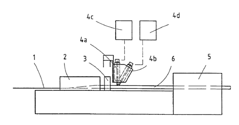
Figure 1 is a schematic representation of an apparatus used to carry out the
process according to a preferred embodiment of the invention; and
Figure 2 is a graph showing the current intensity I of the two molding devices
according to time.
A metal strip I drawn from a strip supply (not shown) is fed to a shaping
station 2, in
which it is gradually shaped into a tube with a longitudinal slit by shaping
cones or shaping rolls,
which are not shown separately. The tube with a longitudinal slit that emerges
from the shaping
station 2 then passes through a shaping ring 3, which serves to hold the
longitudinal edges of the
2a


CA 02509315 2005-06-08
metal strip 1 in an abutting position.

A welding system 4 is arranged immediately after the shaping ring 3. It
consists of the
welding devices or welding torches 4a and 4b, which are arranged in succession
in the
production direction. Each welding device has a nonconsumable electrode (not
shown).

The welding devices 4a and 4b are combined into a unit in a mounting (not
shown), as
described, for example, in the above-cited document DE 22 56 851 A.

The welding device 4a is preferably vertically oriented, whereas the welding
device 4b is
oriented at an acute angle of inclination to the longitudinal axis of the
metal tube of preferably
30-85 . This embodiment guarantees that the welding device 4a or its electrode
comes very

close to the shaping ring 3 and thus prevents the longitudinal edges of the
metal tube from
moving apart.

Each welding device 4a and 4b has its own controllable welding current source
4c and
4d, respectively.

After the welding system 4, an extraction device 5 takes the welded tube 6 and
conveys it
to another station for further processing, which, for example, can be an
extruder for applying a
layer of plastic on the welded tube 6.

The process of the invention is carried out, for example, in the following
way:
Initially, only one of the welding devices 4a and 4b is used in the welding
operation, e.g.,
welding device 4a. If it is then determined that the electrode of welding
device 4a has become
worn out, an auxiliary arc is struck by means that are already well known
between the tube
passing through the welding system and the electrode of welding device 4b. The
auxiliary arc
has no effect on the arc of the welding device already in operation, but it
guarantees stable
burning of the arc of the welding device in the standby position. The welding
current of welding

3


CA 02509315 2011-03-22

device 4a is then gradually reduced, and the welding current of welding device
4b is
simultaneously increased. The important consideration here is that the sum of
the welding
currents of the welding devices 4a and 4b more or less corresponds to the
current intensity
necessary for welding the longitudinal seam of the tube. After the welding
current intensity of
welding device 4b has reached the required magnitude, welding device 4a is
shut off, and the
electrode can be replaced.

The electrode is replaced by pulling it up and out, as described in EP 676 256
B.

When the electrode of welding device 4b becomes worn out, the operation
described
about is repeated in the same way.

The process of the invention can be used with special advantage in the
production of so-
called composite tubes. In this process, a layer of adhesive is first applied
to a plastic tube. The
metal strip 1 is then formed into a metal tube around the plastic tube, and
its longitudinal slit is
then welded. The inside diameter of the metal tube is somewhat larger than the
outside diameter
of the plastic tube that has been provided with a layer of adhesive. After the
weld seam has
cooled, the welded metal tube is pulled down onto the plastic tube. Finally, a
layer of
adhesive is applied to the metal tube, and a layer of plastic is applied by
extrusion.
4


CA 02509315 2005-06-08

The composite tubes produced in this way are flexible, light, and diffusion-
proof. They
are preferably used in floor heating systems.

In Figure 2, the welding current intensity I of the two welding devices 4a and
4b is
plotted as a function of time t. The welding current intensity of welding
device 4a (labeled 4a)
initially runs at a constant magnitude. If it is then determined that the
electrode of welding
device 4a is worn out, an auxiliary arc (see 4b.1) is struck between the tube
passing through the
welding system and the electrode of welding device 4b. The welding current
strength of welding
device 4b is then gradually increased, while the welding current strength of
welding device 4a is
simultaneously reduced.


Representative Drawing
A single figure which represents the drawing illustrating the invention.
Administrative Status

For a clearer understanding of the status of the application/patent presented on this page, the site Disclaimer , as well as the definitions for Patent , Administrative Status , Maintenance Fee  and Payment History  should be consulted.

Administrative Status

Title Date
Forecasted Issue Date 2011-11-29
(22) Filed 2005-06-08
(41) Open to Public Inspection 2005-12-09
Examination Requested 2009-05-28
(45) Issued 2011-11-29
Deemed Expired 2015-06-08

Abandonment History

There is no abandonment history.

Payment History

Fee Type Anniversary Year Due Date Amount Paid Paid Date
Application Fee $400.00 2005-06-08
Registration of a document - section 124 $100.00 2005-09-13
Maintenance Fee - Application - New Act 2 2007-06-08 $100.00 2007-05-28
Maintenance Fee - Application - New Act 3 2008-06-09 $100.00 2008-05-26
Maintenance Fee - Application - New Act 4 2009-06-08 $100.00 2009-05-27
Request for Examination $800.00 2009-05-28
Maintenance Fee - Application - New Act 5 2010-06-08 $200.00 2010-05-27
Maintenance Fee - Application - New Act 6 2011-06-08 $200.00 2011-05-25
Final Fee $300.00 2011-09-14
Maintenance Fee - Patent - New Act 7 2012-06-08 $200.00 2012-05-24
Maintenance Fee - Patent - New Act 8 2013-06-10 $200.00 2013-05-27
Owners on Record

Note: Records showing the ownership history in alphabetical order.

Current Owners on Record
NEXANS
Past Owners on Record
BRUENN, RAINER
FROHNE, CHRISTIAN
HOFFMANN, ERNST
Past Owners that do not appear in the "Owners on Record" listing will appear in other documentation within the application.
Documents

To view selected files, please enter reCAPTCHA code :


To view images, click a link in the Document Description column. To download the documents, select one or more checkboxes in the first column and then click the "Download Selected in PDF format (Zip Archive)" or the "Download Selected as Single PDF" button.

List of published and non-published patent-specific documents on the CPD .

If you have any difficulty accessing content, you can call the Client Service Centre at 1-866-997-1936 or send them an e-mail at CIPO Client Service Centre.


Document
Description 
Date
(yyyy-mm-dd) 
Number of pages   Size of Image (KB) 
Abstract 2005-06-08 1 28
Description 2005-06-08 5 189
Claims 2005-06-08 2 50
Drawings 2005-06-08 1 8
Representative Drawing 2005-11-14 1 5
Cover Page 2005-11-29 1 43
Claims 2011-03-22 1 43
Description 2011-03-22 6 199
Cover Page 2011-10-24 1 44
Correspondence 2005-07-21 1 27
Assignment 2005-06-08 3 81
Assignment 2005-09-13 2 75
Correspondence 2005-10-06 1 24
Assignment 2005-11-03 6 129
Prosecution-Amendment 2009-05-28 2 63
Correspondence 2010-08-10 1 45
Prosecution-Amendment 2010-09-22 2 39
Prosecution-Amendment 2011-03-22 8 266
Correspondence 2011-08-09 1 80
Correspondence 2011-09-14 2 55