Note: Descriptions are shown in the official language in which they were submitted.
CA 02509334 2005-06-08
WO 2004/060256 PCT/US2003/028640
RECEPTACLE FOR APPLICATOR FOR INCONTINENCE INSERT
BACKGROUND OF THE INVENTION
[0001] The present invention generally relates to a receptacle for an
alpplicator for an incontinence insert. The.components of the applicator,
i.e., the
carriage and the plunger, are separately packaged and contain a reference
indication so that the consumer can easily distinguish the plunger from the
carriage
and, can easily distinguish the components of the applicator from sanitary
absorbent articles. Ideally, the receptacle of the present invention contains
plungers that may be reused and therefore the receptacle may contain a number
of plungers that is less than the number of carriages.
[0002] Sanitary absorbent articles are large-scale commercially
manufactured articles used to absorb and retain bodily exudates. Such articles
are
convenient because they are economical yet disposable; they include sanitary
napkins, infant diapers, adult incontinence pads, panty liners, tampons and
the
like.
[0003] Sanitary absorbent articles and particularly feminine sanitary
napkins are made available to the consumer in receptacles containing a
plurality of
sanitary napkins. Traditionally, the industry has used receptacles in the form
of
cardboard boxes. In more recent years the cardboard box has gradually been
replaced by a bag of plastic material. The sanitary napkins held in a
receptacle,
either a cardboard box or a bag of plastic material, are individually
packaged. This
feature allows the user to transport a sanitary napkin outside the protective
environment of the receptacle, such as in a purse or pocket, while keeping the
sanitary napkin free from dirt, stains or impurities. The typical packaging is
in the
form of a pouch of plastic material in which the sanitary napkin is placed.
Immediately before use, the wearer removes the sanitary napkin from the pouch
and installs it in the crotch portion of the undergarment. The pouch is then
discarded.
[0004] Although the packaging described above is useful, differentiation
and proper selection of sanitary absorbent articles on the store shelves is
difficult
because of the many choices of products and manufacturers. In addition, many
users carry in their purse or pocket one or more of the individually packaged
sanitary absorbent articles. As a result, the user must remove the package and
1
CA 02509334 2005-06-08
WO 2004/060256 PCT/US2003/028640
visually inspect it to determine whether the package contains the desired
absorbent article.
[0005] Compounding these present problems, in the near future, it is
anticipated that incontinence inserts will be commercially available.
Incontinence
inserts are being developed to address then need for a non-surgical procedure
and/or device to reduce the involuntary urine loss commonly associated with
"stress urinary incontinence." One way to alleviate the problem of
incontinence is
to place an insert within the vagina to allow the urethra to compress and/or
provide
support for the bladder neck in order to prevent the involuntary loss of
urine.
Inserts developed for such purposes are disclosed in for example, U.S. Pat.
Nos.
6,090,038; 6,090,098; and 6,142,928, the relevant portions of which are
incorporated herein by reference. To properly deliver these and other
incontinence
inserts, applicators have been developed and examples of applicators are
disclosed in commonly assigned, co-pending applications, U.S. Serial No.
09/675,458, and 10/274,855, the relevant portions of which are incorporated
herein
by reference.
[0006] As a result of the anticipated commercial introduction of
incontinence inserts, there is a need in the industry to develop a receptacle
for
applicators for incontinence inserts and for a reference system to allow the
user to
identify the components of the applicator and to distinguish the applicator or
its
components from sanitary absorbent articles.
SUMMARY OF THE INVENTION
[0007] In response to the above need, the present invention provides a
receptacle for storing at least one applicator for an incontinence insert. The
receptacle contains a first individual package and a second individual
package.
The first individual package contains a carriage and includes a first
reference
indicator. The carriage carries an incontinence insert. The second individual
package contains a plunger and includes a second reference indicator. The
plunger mates with the carriage so that the incontinence insert can be
dispensed.
Desirably, the first reference indicator and the second reference indicator
differ so
that the user can distinguish between the carriage and the plunger and can
distinguish each from, for example, sanitary absorbent articles.
2
CA 02509334 2005-06-08
WO 2004/060256 PCT/US2003/028640
[0008] Each of the first reference indicator and the second reference
indicator is selected from the group consisting of visual indicators, tactile
indicators, or a combination of both. Visual indicators include, but are not
limited
to color, written notice or indicia, pictograph, icon, or a combination of the
above.
Tactile indicators include texturing (e.g., knurling), the use of differing
materials,
embossing, or a combination. The first reference indicator may be provided on
the
first individual package, the carriage, or both. The second reference
indicator may
be provided on the second individual package, the plunger, or both.
[0009] Advantageously, because the plunger is packaged separately
from the carriage, the consumer can dispense the incontinence insert either
digitally or with the plunger. As a result, in certain aspects of the present
invention,
the receptacle provides discreet portability and convenience.
[0010] Another aspect of the present invention includes a receptacle that
contains a plurality of first individual packages and a plurality of second
individual
packages. Each of the first individual packages contains a carriage having an
incontinence insert disposed within the carriage and includes a first
reference
indicator. Each of the second individual packages contains a plunger that
mates
with the carriage to dispense the incontinence insert and includes a second
reference indicator. Desirably, the first reference indicator differs from the
second
reference indicator. In addition, the number of second individual packages may
be
less than the number of first individual packages because the plungers may be
reused or because the plunger may not be required since the incontinence
insert
can be dispensed without the use of the plunger, such as digitally.
[0011] The present invention also contemplates a kit that includes at
least one individually packaged carriage within which an incontinence insert
is
located, at least one individually packaged plunger, and a common receptacle
that
encompasses the at least one individually packaged carriage and at least one
individually packaged plunger. Also contemplated within the present invention
is a
method of providing an incontinence insert applicator.
BRIEF DESCRIPTION OF THE DRAWINGS
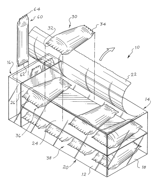
[0012] FIG. 1 is a perspective view of one embodiment of a receptacle
that shows two separated layers of a plurality of first individual packages
with each
package containing a carriage having an incontinence insert disposed within
the
3
CA 02509334 2005-06-08
WO 2004/060256 PCT/US2003/028640
carriage. The receptacle also contains a plurality of second individual
packages,
with each package containing a plunger that mates with the carriage to
dispense
the incontinence insert.
[0013] FIG. 2 is an exploded view of an individual package containing a
carriage within which an incontinence insert is disposed. The package and the
plunger are each provided with a reference indicator.
[0014] FIG. 3 is an exploded view of an individual package containing a
plunger that mates with the carriage to dispense the incontinence insert. The
package and the carriage are each provided with a reference indicator.
[0015] FIG. 4 is an exploded view of a plunger and carriage after each of
the plunger and carriage have been removed from their respective package and
are ready to dispense the incontinence insert.
DESCRIPTION OF THE INVENTION
[0016] Referring now to the drawings and initially to FIG. 1, a receptacle
10 according to the present invention is shown in a pre-assembled
configuration.
The receptacle 10 includes and stores at least one first individual package 30
that
contains a carriage 40 and at least one second individual package 60 that
contains
a plunger 70. The carriage 40 carries an incontinence insert 50 that can be
dispensed within a vaginal cavity. The plunger 70 mates with the carriage 40
to
dispense the incontinence insert 50. Alternatively, the incontinence insert 50
may
be digitally dispensed from the carriage 40.
[0017] The carriage 40 and the plunger 70 may be made of any suitable
material such as molded plastic, paperstock, etc. The carriage 40 and the
plunger
70 may also be made so that the plunger 70 mates with the carriage 40 in only
a
particular manner so that the consumer can easily join the plunger 70 with the
carriage 40 to dispense the insert 50.
[0018] The receptacle 10 may be in the form of a flexible bag made of
synthetic material such as plastic film. Other forms of packaging can be used
without departing from the spirit of the invention. It is further envisioned
that the
receptacle 10 may be made from coated paper, woven material, non-woven
material, polyethylene, polypropylene, co-polymers, extruded polymer, thermo-
formed materials, andlor cardboard without departing from the scope of the
4
CA 02509334 2005-06-08
WO 2004/060256 PCT/US2003/028640
present invention so long as the material can physically hold at least one
first
individual package 30 and at least one second individual package 60.
[0019] In the embodiment shown in FIG. 1, the receptacle 10 contains a
plurality of first individual packages 30 and a plurality of second individual
packages 60. The receptacle 10 shown in FIG. 1 can include any number of first
individual packages 30 that are selected for the convenience of an end user.
For
example, the receptacle 10 may include about thirty first individual packages
30
(and in turn about thirty carriages 40 with incontinence inserts 50). It is
envisioned
that the receptacle 10 include a suitable number of first individual packages
30 to
provide a supply of incontinence inserts 50 for one conventional week (i.e.,
seven
days). Alternatively, it is contemplated that the receptacle 10 may be sized
such
that it carries only a few first individual packages 30 and a single second
individual
package 60 so that the receptacle 10 can be discreetly carried in a purse,
handbag, or pocket.
[0020] The receptacle 10 may be made in many ways without departing
from the scope of the present invention. In the embodiment illustrated in FIG.
1,
the receptacle 10 comprises a substantially rectangular front 12, a back 14
opposite the front, a first side 16, a second side 18 opposite the first side,
a bottom
20, and a top 22. Where the receptacle 10 is made from plastic, the top 22 can
be
partially removed to provide access to the inside of the receptacle 10. Where
the
receptacle 10 is made from cardboard or similar substance, the top 22 may be
reclosable, using any construction known to those skilled in the art.
[0021] FIG. 1 also shows the receptacle 10 after it has been opened to
access the first 30 and second 60 individual packages inside. Although the
first
individual packages 30 may be arranged in many ways without departing from the
scope of the present invention, in one embodiment shown in FIG. 1, the first
individual packages 30 are arranged in two layers separated by a separator 24.
The separator 24 may be constructed of any suitable material. For example, the
separator 24 may be constructed of plastic, cardboard, sheetstock, or any
other
suitably stiff material that can support and separate a first layer 36 of
first individual
packages 30 from a second layer 38 of first individual packages 30.
[0022] The receptacle 10 also includes at least one second individual
package 60 and, in the embodiment shown in FIG. 1, the receptacle 10 includes
a
5
CA 02509334 2005-06-08
WO 2004/060256 PCT/US2003/028640
number of second individual packages 60, each of which includes a plunger 70.
The number of second individual packages 60 is desirably less than the number
of
first individual packages 30 because the user may digitally dispense the
incontinence insert. In addition and alternatively, the plungers 70 can be
reusable
and thus, one plunger 70 can be used to dispense an incontinence insert 50
from a
number of carriages 40. In this regard, the second individual packages 60 can
be
formed in a manner to be resealable.
[0023] As shown in FIG. 1, the second individual packages 60 are
separated from the first individual packages 30 by a separator 26. This
separator
26 may be constructed from the same or different material as that used to
separate
the layers of first individual packages 30. In the embodiment shown in FIG. 1,
the
second individual packages 60 are provided adjacent one side 16 of the
receptacle
10 so that the second individual packages 60 can be easily located and
obtained
from the receptacle 10.
[0024] The first and second individual packages 30, 60 may be made
from any suitable material such as extruded or laminated flexible poly-based
films
or other non-woven materials.
[0025] The first individual package 30 has a first end 32 and a second
end 34. Each end is desirably sealed to provide a sanitary enclosure for the
carriage. Similarly, the second individual package 60 has a first end 62 and a
second end 64. Each end is desirably sealed to provide a sanitary enclosure
for
the plunger. As noted above, it is desired that the plunger be reusable. In
this
instance, it is desirable if the second individual package 60 is made of a
material
that can be resealed a number of times so that the plunger 70 can be removed
and
reinserted into the second individual package 60 and the package can be
resealed
to maintain some degree of cleanliness.
[0026] The first and second packages 30, 60 may be clear or provided
with a color that forms all or part of the first or second reference indicator
80, 90.
Where the first 30 or second 60 individual packages are clear or transparent,
the
respective carriage 40 or plunger 70 may be colored, which may form all or
part of
the first 80 or second 90 reference indicators.
[0027] As noted above, in order to distinguish the carriages 40 from the
plungers 70 and the components of the applicator 100 from other sanitary
6
CA 02509334 2005-06-08
WO 2004/060256 PCT/US2003/028640
absorbent articles, a first 80 and/or a second 90 reference indicator are
provided.
The first 80 and second reference 90 indicators relate to the carriage 40 or
the
plunger 70, respectively. The first reference indicator 80 can be provided on
the
first individual package 30, the carriage 40, or both. Similarly, the second
reference indicator 90 can be provided on the second individual package 60,
the
plunger 70; or both.
[0028] Each of the first 80 and second 90 reference indicators are
selected from the group consisting of visual indicators, tactile indicators,
or a
combination of both. Visual indicators include, but are not limited to color,
written
notice or indicia, pictograph, icon, or a combination of the above. Tactile
indicators
include texturing (e.g., knurling), the use of differing materials, embossing,
or a
combination.
[0029] The term "color" as used in the present specification and claims
relates to the phenomenon of visual perception that enables one to
differentiate
between otherwise identical objects and therefore the term includes the lack
of
color such as those commonly known as white and black. Colors may be
expressed in terms of "hue", i.e., that attribute of colors that permits them
to be
classified as red, orange, yellow, green, blue, indigo, violet, etc. or as
intermediate
between any contiguous pairs of colors. Colors (hues) are also commonly
perceived and referred to in terms of their relative intensities, using terms
such as
light, medium, dark, bright, intensity, (i.e., saturation or shades) and the
like, either
between colors or within a range of "shades" for otherwise the same color.
Thus,
one can readily perceive the difference between "light" (or "pale"), medium,
and
dark or ("deep") shades of red, green, blue, etc.
[0030] There are various systems of defining color and intensity. One
common color system is the HSB system. In Adobe~ Photoshop~, the color
charts define a specific color by using three characters of HSB. For example,
in
the HSB system, a color H can be defined along the circumference of a cone
from
0 to 360, S refers to saturation, which is the distance from 0 to 100 from the
center
of the cone, and B, which is the black-white scale and ranges from 0 to 100.
[0031] There are an unlimited number of colors available and varying H,
S, and B can vary the various intensities of what appears to be the same
color.
For example, in the HSB system, if H is constant about 240 and B is constant
7
CA 02509334 2005-06-08
WO 2004/060256 PCT/US2003/028640
about 100, while S is changed from about 100 to about 60, the color remains a
distinct blue but changes in the depth or intensity of the color. Similarly,
if H is
constant about 250 and S is about 100 and B is about 100, the color is a color
that
is definitely blue, but as B changes from about 100 to about 80, the color
changes
so it is a darker more gray blue that causes a darker intensity. In another
example,
if S and B are about 100, a distinct range of dark to light blue occurs as the
H
changes from about 190 to 260. One skilled in the art will appreciate that a
similar
set of examples can be made for several other colors by simply going to
Photoshop~ and going to the "color picking" area.
[0032] The written notice or indicia may include a 'word or a label or a set
of words or labels that communicate in writing the difference between the
carriage
40 and the plunger 70. The pictograph or icon may be comprised of one or more
icons of such a nature as to communicate the difference between the carriage
40
and the plunger 70.
[0033] Each of the reference indicators 80, 90 can be realized by
creating markings on the packaging, on the carriage 40 or the plunger 70, or
on
both so that the first and second reference indicators are readily visible to
the user.
For example, the markings may by created by a printing process. Alternatively,
the
markings may be created by molding, molded plastic, embossing, die-cutting,
application of a separate stick-on tab or label or any other suitable method.
[0034] The application of the markings by embossing presents the
advantage of allowing the markings to be understood by the sense of touch.
This
is useful for blind people or in dark environments where there is not enough
light to
read the markings. In this regard, the first and second reference indicators
80, 90
may include the tactile indicators described above or by texturing all or a
portion a
portion of each of the packages, the carriage or plunger, or both, by the use
of
different materials for the packages 30, 60 or the carriage 40 or plunger 70
or both,
or by any other suitable method.
[0035] In one embodiment, the plunger 70 may be provided with a
second reference indicator 90 in the form of a color such as pink or blue. The
second individual package 60 can be a transparent or clear package so that the
plunger 70 can be easily identified. At the same time, the first individual
package
30 can be wrapped in a non-white package such as blue, so that the carriage 40
8
CA 02509334 2005-06-08
WO 2004/060256 PCT/US2003/028640
can be easily distinguished both from the plunger 70 and from other sanitary
absorbent articles such as tampons.
[0036] The present invention also includes a consumer product kit that
includes at least one individually packaged carriage 40 within which an
incontinence insert 50 is located, at least one individually packaged plunger
70,
and a common receptacle 10 that encompasses the at least one individually
packaged carriage 40 and at least one individually packaged plunger 70. The at
least one individually packaged carriage 40 includes a first reference
indicator 80
and the at least one individually packaged plunger 70 includes a second
reference
indicator 90. Accordingly, the user can distinguish between the plunger 70 and
the
carriage 30. Desirably, the first reference indicator 80 differs from the
second
reference indicator 90. In addition, when the plunger 70 is removed from its
package 60 and the carriage 40 is removed from its package 30, the plunger 70
is
received within the carriage 40 such that the incontinence insert 50 can be
appropriately dispensed into the vaginal cavity.
[0037] As noted above, it is contemplated that the first reference
indicator 80 and the second reference indicator 90 be provided on the carriage
40
and the plunger 70, respectively. When the first reference indicator 80 is
provided
on the carriage 40 and the second reference indicator 90 is provided on the
plunger 70, each may be provided in a respective suitable location so that
when
the plunger 70 is correctly aligned with the carriage 40, the first 80 and
second 90
reference indicators are aligned.
[0038] The present invention also contemplates a method of providing
an applicator 100 for an incontinence insert 50. The method includes providing
at
least one individually packaged carriage 40 within which an incontinence
insert 50
is located, providing at least one individually packaged plunger 70. The at
least
one individually packaged carriage 40 includes a first reference indicator 80
and
the at least one individually packaged plunger 70 includes a second reference
indicator 90. The plunger 70 is dimensioned such that it mates with the
carriage
40 so that the incontinence insert 50 can be dispensed. Desirably, the first
reference indicator 80 differs from the second reference indicator 90.
[0039] While the invention has been described in conjunction with
specific embodiments, it is to be understood that many alternatives,
modifications,
9
CA 02509334 2005-06-08
WO 2004/060256 PCT/US2003/028640
and variations will be apparent to those skilled in the art in light of the
foregoing
description. Accordingly, this invention is intended to embrace all such
alternatives, modifications, and variations that fall within the spirit and
scope of the
appended claims.