Note: Descriptions are shown in the official language in which they were submitted.
CA 02509909 2005-06-13
WO 2004/057314 PCT/CA2003/001996
METHOD AND SENSOR FOR DETECTING A CHEMICAL SUBSTANCE USING AN
OPTICALLY ANISOTROPIC MATERIAL
FIELD OF THE INVENTION
[0001] The present invention relates to a method and a
sensor for detecting a chemical substance, and to a method
and a sensor for detecting a presence of liquid, gas or vapor
of a chemical substance through changes in an optically
anisotropic material upon exposure to such. liquid, gas or
vapor. The method and the sensor have applications such as an
end-of-service-life indicator which may be incorporated in an
air purifying device so as to provide a warning when the life
of a filter is near to exhaustion. It may also be used as a
remaining-life indicator,`'a--dosimeter, etc.
BACKGROUND
[0002] Chemical detection is often mandatory for
industrial or safety applications and simple, reliable
sensors should be implemented for process, control or for
security monitoring.
[0003] A number of chemical sensors for detection of
chemicals are already known in the art, based on changes in
characteristics such as physical, chemical, electrochemical
or optical properties.
[0004] Chemical detection may be performed using
electronic methods. For example, composite polymers having
their electrical impedance changing upon exposure to vapors
(e.g. commercial products made by the company Cyrano Sciences
Inc.) may be used for this purpose. U.S. Patent Nos.
5,512,882 (Stetter et al.), 4,631,952 (Donaghey), and
5,238,729 (Debe) show examples of chemical sensors of-this-
type. In general, these types of sensing methods require a
large variety of polymers or other types of materials with a
1
CA 02509909 2005-06-13
WO 2004/057314 PCT/CA2003/001996
selection of responses depending on the chemical species to
detect, making them more complicated to produce and to use.
[0005] U.S. Patent Nos. 4,846,548 (Klainer), 5,828,798
(Hopenfeld), 6,278,106 (Muto et al.), 4,834,496 (Blyler, Jr.
et al.), 5,436,167 (Robillard), 4,699,511 (Seaver), 4,940,328
(Hartman) , 6,007,904 (Schwotzer et al.), 5,783,836 (Liu et
al.), 5,015,843 (Seitz et al.), 5,308,771 (Zhou et al.),
4,998,017 and Re. 35,355 (Ryan et al.), 5,525,800 (Sanghera
et al.), 4,732,480 (Fortunato et al.) and European patent
EP 0 536 656 (Guenter et al.) show examples of optically
based chemicals sensors and apparatus including fiber optic
chemical sensors (FOGS).
[0006] A number of these FOCS use changes in the guiding
properties of the optical fiber, including transmission
parameters such as intensity, ellipticity and reflective or
refractive angles. Many of the optical methods involved in
the above sensors and apparatus require specific cladding or
coating materials depending on the chemical species to be
detected, which make them not very practical in industrial
applications where different chemical species may be present.
Some difficulties may arise during development of such
chemically reacting cladding or coating such as compatibility
of the reactive molecules with the desired refractive index
range value, or adhesion problems between the core and the
reactive cladding or coating of such fibers. Their
applications may thus be limited to specific configurations.
[0007] Many of the optical chemical sensors use a
spectroscopic approach and rely on light absorption at
specific wavelengths to detect chemical species. Such
spectroscopic approaches can be a very powerful tool for
chemical characterization and quantification but are usually
expensive and difficult to implement, and require usually
2
CA 02509909 2005-06-13
WO 2004/057314 PCT/CA2003/001996
some good knowledge for adjustments and for data
interpretation.
[0008] In order to increase the contact surface of the
sensor with chemicals to be detected, porous materials with
high surface area are often used. Capillary condensation and
use of porous silicon as sensing material are described in
the literature (see e.g. Gelb, L.D. et al., "Phase separation
in confined systems", Rep. Prog. Phys. 62, 1999, pp. 1573-
1660; Gross, E. et al., "Highly sensitive recognition element
10' based on birefringent porous silicon layers", J. Appl. Phys.
90 No. 7, 2001, pp. 3529-3532; Liu, R. et al., "Novel porous
silicon vapour sensor based on polarization interferometry"
Sensors and Actuators B 87, 2002, pp. 58-62; Gao, J. et al.,
"Vapor sensors based on optical interferometry from oxidized
microporous silicon films" Langmuir 18, 2002, pp. 2229-2233;
Gao, J. et al., "Porous-silicon vapour sensor based on laser
interferometry" Appl. Phys. Lett. Vol. 77 n 6, 2000, pp. 901-
903; Canham, L.T., "Properties of Porous Silicon", Canham L.
Ed., EMIS Data reviews series No. 18, 1997, INSPEC publ., pp.
154-157; Bjorklund, R. B. et al., "Color changes in thin
porous silicon films caused by vapor exposure", Appl. Phys.
Lett. 69 (20), 1996, pp. 3001-3003; Zangooie, S. et al.,
"Vapor sensitivity of thin porous silicon layers", Sensors
and Actuators B 43, 1997, pp. 168-174; Zangooie, S. et al.
"Reversible and irreversible control of optical properties of
porous silicon superlattices by thermal oxidation, vapour
adsorption, and liquid penetration" J. Vac. Sci. Technol. A
16(5), 1998, pp. 2901-2912); as well as in the U.S. Patent
Nos. 6,130,748 (Kruger et al.), 6,248,539 (Ghadiri et al.),
5,338,415 (Sailor et al.) and 5,453,624 (Sailor et al.)
Porous glass can also be used as described in U.S. Patent
Nos. 5,250,095 (Sigel, Jr. et al.) and 6,375,725 (Bernard et
al ) .
3
CA 02509909 2005-06-13
WO 2004/057314 PCT/CA2003/001996
[0009] In cases where porous materials such as porous
silicon films are used, fragility due to high porosity (e.g.
usually over 50-80%) associated with small film thicknesses
(e.g. typically 10-100 m) makes them brittle and less
attractive for industrial applications where robust sensors
are required, especially if they must be embedded inside an
absorbent material. Besides aging problems related to surface
oxidation and chemical stability, another drawback of porous
silicon sensors is that spectral shifts occur in the far red
and near infrared region (-800-1700 nm) which means that the
human eye could not be used as a light detector. However in
some cases, color changes, characterized by ellipsometry, are
related to the refractive index of the solvents condensing
into the pores and replacing air. Since lower partial
pressures of solvent cause no color changes in the film, only
the variation in the ellipsometric angles at certain energies
could be applied to sensing applications.
[0010] Air purifying devices, including air purifying
respirator cartridges and canisters, are widely used in the
civil and military industries to protect the workers against
harmful effects of toxic materials. Such devices usually
consist of a filter chamber filled with adsorbent material
that traps (e.g. adsorbs or absorbs) vapors or gases on its
surface or within its porous structure. As the adsorbent
material is completely filled, the air-purifying device loses
protective capability for the user against the contaminant.
This could have dramatic effects, especially when the
contaminant has poor warning properties, e.g. if its odor,
taste or irritation limit is greater than the permissible
exposure limit or if there is insufficient toxicological data
to determine an exposure limit.
[0011] In establishing new certification standards in
1984, the U.S. National Institute for Occupational Safety and
4
CA 02509909 2010-07-16
Health (NIOSH) encouraged the development of active end-of-
service-life indicators. Such indicators should detect the
presence of contaminants and provide an unambiguous signal
warning the user that the filter of the air-purifying device
is almost exhausted. Examples of chemical sensors proposed
for use as end-of-service-life indicators are shown in U.S.
Patent Nos. 4,154,586 (Jones et al.) and 4,530,706 (Jones),
4,684,380 (Leichnitz), 4,326,514 (Eian), 5,659,296 (Debe et
al.), 4,155,358 (McAllister et al.), 4,146,887 (Magnante),
4,847,594 (Stetter), 6,375,725 (Bernard et al.) and in
international application No. WO 02/22237 (Curado et al.).
(0012] End-of-service-life indicators may involve a visual
color change that warns the user to replace the filter. Such
color changes are sometimes induced by chemical reactions of
a usually single use color indicator. One drawback of such
chemical color indicators is that they are usually very
specific to the chemical or class of chemicals (such as
acids) they should react with.
SUMMARY
[0013] According to one aspect of the present invention, there is provided a
method
for indicating an end of life of a respirator cartridge, an air purifying
cartridge or a
filtration cartridge by detecting a chemical substance in an analyte,
comprising steps
of:
providing an optically anisotropic material forming a porous fiber or slab in
a
sorbent bed of the respirator cartridge, air purifying cartridge or filtration
cartridge;
subjecting the sorbent bed to the analyte;
5
CA 02509909 2010-07-16
passing visible light through the anisotropic material by transilluminating
the
anisotropic material with the light;
collecting at least a portion of the passed visible light; and
detecting a change in a polarization state of the collected visible light, the
change being indicative of the chemical substance in the analyte having
reached the
anisotropic material through the sorbent bed.
[0014] According to another aspect of the present invention, there is also
provided a
sensor for indicating an end of life of a respirator cartridge, an air
purifying cartridge
or a filtration cartridge by detecting a chemical substance in an analyte,
comprising:
an optically anisotropic material forming a porous fiber or slab provided in a
sorbent bed of the respirator cartridge, air purifying cartridge or filtration
cartridge, the
sorbent bed to be subjected to the analyte;
a light supply passing visible light through the anisotropic material by
transilluminating the anisotropic material with the light;
a collector capturing at least a portion of the passed visible light; and
a detector characterizing or quantifying a change in a polarization state of
the
collected visible light, the change being indicative of the chemical substance
in the
analyte having reached the anisotropic material through the sorbent bed.
[0019] The following provides a non-restrictive summary of
certain features of the invention which will be more fully
described hereinafter.
[0020] The invention utilizes changes of optical
anisotropy that occur in certain classes of materials,
especially but not restrictively porous optical materials
such as porous glass and polymeric materials, upon exposure
to liquid, gases or vapors of chemical substances. The change
6
CA 02509909 2010-07-16
of optical anisotropy can be observed for example as optical
birefringence, dichroism or selective absorption, anisotropic
diffusion of light or anisotropic scattering of light.
[0021] As one example of an anisotropic material, a porous
glass exhibiting optical birefringence may be used to detect
liquids, gases or vapors. The porous glass may be made from a
phase separation process followed by chemical etching through
which the optical birefringence may be controlled. Adsorption
of liquid by imbibition into the pores or of gas or vapor
molecules by capillary condensation into the pores changes
for example the optical birefringence of the porous glass,
causing a porosity-induced change in optical anisotropy that
may be detected using several methods. The change may for
7
CA 02509909 2005-06-13
WO 2004/057314 PCT/CA2003/001996
example be detected by observing a color shift of the light
transmitted through the porous glass placed between two
crossed polarizers, or by comparing the transmitted light
intensity at different wavelengths.
[0022] An optically birefringent multilayer porous thin
film may also be used as the anisotropic material. The
optical birefringence of the multilayer thin film changes in
the same manner as with porous glass and may be detected in
the same manner.
[0023] An optically birefringent polymer, an optically
birefringent polymer composite, or an optically birefringent
multilayer polymer film may also be used. The optical
birefringence of the polymer may for example change in the
presence of a chemical substance due to swelling of the
polymer. These changes may be measured in the same manner as
with porous glass.
[0024] An optically dichroic polymer, or an optically
dichroic polymer composite, or an optically dichroic
multilayer polymer film may also be used. The dichroism of
the polymer may for example change in the presence of a
chemical substance due to swelling of the polymer. These
changes may be observed by measuring the intensity changes of
a given polarization state of light or by measuring changes
in the ratio of intensities of two mutually orthogonal states
of polarization.
[0025] An optical anisotropically scattering or an optical
anisotropically diffusing material, such as porous glass or a
composite polymer, may be used. The optical anisotropy of the
scattering of light or of the diffusion of light may be
affected in the same manner as mentioned above in the case of
porous material (glass, thin film, etc.) or in the case ofa
polymer. Polarization-dependent scattering or diffusion
changes may for example be observed by measuring changes in
8
CA 02509909 2005-06-13
WO 2004/057314 PCT/CA2003/001996
the intensity of a given polarization state of light or by
measuring changes in the ratio of intensities of two
orthogonal states of polarization. These changes may also be
observed by measuring the geometric distribution of the
diffused or scattered light in two mutually orthogonal
directions.
[0026] A hydrophobic agent or treatment may be applied on
the anisotropic material (porous glass, polymer, etc.) to
reduce sensitivity to water vapor while maintaining
sensitivity to other chemicals. Specific surface treatments
or surface chemistry may also be applied on the anisotropic
material to change its surface energy or its affinity to
specific chemicals.
BRIEF DESCRIPTION OF THE DRAWING
[0027] A detailed description of several preferred
embodiments will be given herein below with reference to the
following figures, in which like numbers refer to like
elements:
[0028] Figure 1 is a schematic diagram showing an optical
arrangement of a birefringence-based sensor.
[0029] Figure 2 is a schematic diagram showing optical
effects in a birefringence-based sensor.
[0030] Figure 3 is a schematic diagram showing optical
effects in a dichroism-based sensor.
[0031] Figures 4-7 are schematic diagrams showing several
possible reflective optical arrangements of a birefringence-
based sensor.
[0032] Figure 8 is schematic diagrams showing several
possible semi-reflective optical arrangements of a
birefringence-based sensor.
[0033] Figures 9-11 are graphs showing respectively
effects of birefringent material thickness, of variable
9
CA 02509909 2005-06-13
WO 2004/057314 PCT/CA2003/001996
birefringence, and of polarizer orientation in various
disclosed sensors.
[0034] Figures 12A through 15B are schematic diagrams
showing several constructions of various disclosed sensors.
[0035] Figures 16A through 18B are schematic diagrams
showing several implementations of an embedded sensor for use
in air filtration or purification units.
[0036] Figure 19 is a graph illustrating transmitted power
curves as a function of wavelengths for two different
thicknesses of a birefringent porous glass.
[0037] Figure 20 is a graph illustrating transmitted power
curves as a function of wavelength for a birefringent porous
glass under different chemical conditions.
[0038] Figure 21 is a graph illustrating transmitted power
curves as a function of time for a birefringent porous glass
under different chemical conditions.
[0039] Figure 22 is a graph illustrating transmitted power
curves as a function of time for a birefringent porous glass
under different transiting chemical conditions showing
repeatability of the disclosed method.
[0040] Figures 23-25 are graphs respectively illustrating
variation intensity curves measured at 550 nm and 800 nm of
an optical birefringent porous glass sensing element inserted
in an activated carbon bed of an organic vapor cartridge, and
corresponding intensity ratio curves and spectra.
DETAILED DESCRIPTION OF THE PREFERRED EMBODIMENTS
[0041] As used in connection with this disclosure, the
term "light" refers to electromagnetic radiation generally.
[0042] As used in connection with this disclosure, the
expression "visible light" refers to light between 0.38 and
.78 pm
CA 02509909 2005-06-13
WO 2004/057314 PCT/CA2003/001996
[0043] As used in connection with this disclosure, the
expression "optical index" refers to a generally complex
value containing a real and an imaginary component, with the
real component corresponding to the refractive index for a
material or volume of space and the imaginary component
corresponding to the optical absorption coefficient for a
material or volume of space.
[0044] As used in connection with this disclosure, the
phrase "passing light through" when used with respect to a
material refers to light that enters the material by
refraction through a surface of incidence and propagates to a
generally opposing surface where it exits the material by
refraction.
[0045] As used in connection with this disclosure, the
terms "transilluminate", "transillumination" and
"trans illumina-ting" when used with respect to an object
refer to illumination of the object by passing light through
its generally opposing walls.
[0046] As used in connection with this disclosure, the
term "collecting" when used with respect to light refers to
capturing light using an aperture, lens, goniometer,
integrating sphere, human eye or other device that can sample
or concentrate available light.
[0047] As used in connection with this disclosure, the
term "detecting" when used with respect to light refers to
characterizing or quantifying a property of light using
visual observation, a sensor or device.
[0048] As used in connection with this disclosure, the
term "anisotropic" when used with respect to a material
refers to variation in a measured physical property depending
upon the direction in -the material along which the
measurement is taken.
11
CA 02509909 2005-06-13
WO 2004/057314 PCT/CA2003/001996
[0049] As used in connection with this disclosure, the
expression "optical anisotropy" refers to variation in the
measured refractive index or optical absorption coefficient
for a material depending upon the direction in the material
along which the measurement is taken.
[0050] As used in connection with this disclosure, the
term "birefringence" refers to an anisotropic polarization
state behavior for the real part of the optical index,
generally manifested by the phase retardation of one
polarization state relative to another polarization state in
an incident beam.
[0051] As used in connection with this disclosure, the
term "birefringent" when used with respect to a material
refers to a material that selectively retards the phase of
one polarization state relative to another polarization state
in an incident beam.
[0052] As used in connection with this disclosure, the
expression "optical dichroism" refers to an anisotropic
absorption coefficient behavior for the imaginary part of the
optical index, generally manifested by the selective
absorption of one polarization state relative to another
polarization state in an incident beam.
[0053] As used in connection with this disclosure, the
term "dichroic" when used with respect to a material refers
to a material that absorbs one polarization state more
strongly than another polarization state in an incident beam.
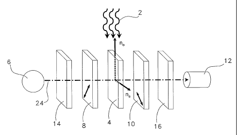
[0054] Referring to Figure 1, there is shown an optical
arrangement of a sensor, for detecting a chemical substance
in an analyte as depicted by arrows 2. The sensor has an
anisotropic material 4 to be subjected to the analyte 2.
Anisotropic material 4 acts as a chemical sensing element.
The anisotropic material 4 may be a birefringent material
placed between two linearly crossed polarizers 8, 10 which
12
CA 02509909 2005-06-13
WO 2004/057314 PCT/CA2003/001996
are between a light source 6 and a light detector 12. The
chemical substance to be detected may be for example a
solvent or any gas vapor or liquid whose presence could
change the optical anisotropy of the sensing element.
[0055] The light source 6 provides light to be passed
through the anisotropic material 4. The light source 6 may be
a source of broadband light e.g. a white incandescent or
halogen light, colored light as produced e.g. from a light
emitting diode (LED) or from filtered light, or any kind of
electromagnetic radiation in general. Emission line sources
such as mercury, argon, sodium sources as well as laser
sources may be used. Ambient light or daylight may also be
used as the light source, depending on the intended
application and the operating conditions of the sensor.
Likewise, the light source 6 could be non-polarized or
polarized. A filter 14 may be placed after the light source 6
to select or reject a range of wavelengths. Another filter 16
may be placed before the detector 12 to enhance the signal
contrast or to cut unwanted wavelengths. The filters 14, 16
should be considered as optional elements in all subsequent
figures.
[0056] The linear polarizer 8 may be of any type, e.g. a
simple polarizing film such as PolaroidTM film, a multilayer
polarizing film, polarizing cube beam splitters, etc. After
passing through the polarizer 8, the light is linearly
polarized.
[0057] The linear polarizer 10, similar to polarizer 8
acts as a linear analyzer.
[0058] The detector 12 may be a photoelectronic device or
in certain cases simply a human eye as will be seen below.
[0059] Referring to Figure 2, the optical axis of the
birefringent material 4 is placed in the propagation plane
(normal to the propagation axis 24) preferably at 45 with
13
CA 02509909 2005-06-13
WO 2004/057314 PCT/CA2003/001996
respect to the linear polarization direction. The electrical
field vector E of linear polarized light is decomposed in
two orthogonal projections Ex, Ey along the ordinary no and
extraordinary ne refractive indices, as depicted in diagram
18. Due to birefringence, each projection of the electrical
field vector experiences a different refractive index and
thus' a different light path resulting in a phase shift AO
between the two projected components of the electric field
vector as depicted in diagram 20. At a given wavelength A
the phase shift AO is given by:
2ic-d-An
~~_ (1)
where d is the thickness of the birefringent sample 4 and
An = fe - no is the birefringence.
[0060] The linear analyzer 10 is preferably crossed (e.g.,
at 900) with the polarizer 8 to make sure that the only light
passing through the analyzer 10 is light that has been
rotated by the birefringent sample 4. The analyzer 10
transmits along its axis of polarization the components of
the two phase shifted projected electrical field vectors that
experienced different optical paths, as depicted in diagram
22.
[0061] The detector 12 may be simply a naked eye, an
imaging system with a CCD camera (not shown), a
spectrophotometer (not shown), or just a photodiode (not
shown). For a uniaxially birefringent material, the output
14
CA 02509909 2005-06-13
WO 2004/057314 PCT/CA2003/001996
intensity 'outl for 900 crossed polarizers at a given
wavelength A is given by:
Iout1 = K = Isource . sln2 = d = An
2 (2)
where K is a positive factor (:!~1) that takes into account
all the power losses such as partial reflections and possible
diffusion along the optical path 24, 'source is the source
intensity, d is the thickness of the birefringent material
and On = ne - no is the birefringence.
[0062] In such conditions, maxima of transmission occur
when:
d=IDnI = 2m+1= (3)
2
where m = 0, 1, 2, ... ,
and minima of transmission occur when:
d=~An)=m=A (4)
The transmittance spectrum depends thus on the thickness d
as well as on the birefringence An of the anisotropic
material 4 as shown in the graphs presented in Figures 9 and
10 respectively.
[0063] Referring to Figure 9, there is shown the effect of
increasing thickness for a given birefringence.
[0064] Referring to Figure_10, there is shown the effect
of increasing birefringence for a given thickness.
[0065] Referring to Figure 11, there is shown the
theoretical transmittance calculated in the wavelength range
CA 02509909 2005-06-13
WO 2004/057314 PCT/CA2003/001996
of A = 300 nm to A = 1000 nm for an optical birefringent
material (An= 0.0015) and a constant thickness d = 400 m
placed at 450 between ideal crossed and parallel polarizers
as depicted by curves 88, 90 respectively.
[0066] The higher the thickness or absolute value of the
birefringence, the more maxima and minima are present in the
transmittance spectra.
[0067] When the presence of a chemical substance affects
the birefringence or -the thickness of the anisotropic
material, the phase shift AO changes and is detected by the
detector 12, either by a change in intensity at a given
wavelength or given wavelengths, or by a change in the
transmitted spectrum. The change may be measured for example
using a spectrophotometer or interpreted by noting a change
in the transmitted color.
[0068] Improved sensitivity may be achieved with crossed
(e.g., at 90 ) polarizer 8 and analyzer 10 and with a
birefringent material 4 with its optical axis placed at 450
relative to the linear polarization axis, but angular
precision need not be strictly observed and a tolerance in
these angles, e.g. 10 , may be acceptable.
[0069] An advantage of the Figure 1 arrangement is that
the only light that is detected is light that has been
shifted by the birefringent material 4, since other light
from the source 6 would be stopped by the crossed analyzer
10. This can provide much better sensitivity than is obtained
when the polarizers are omitted and transmission intensity
alone is measured.
[0070] The polarizer 8 and the analyzer 10 may also have
parallel optical axes. In such configuration, at a given
wavelength 2 , the output intensity 'out// is now given by:
16
CA 02509909 2005-06-13
WO 2004/057314 PCT/CA2003/001996
Iout /I = K ='source . cost 9. d = An (5)
2 A
In that case, the transmitted spectrum of the sensing element
is inverted compared to the configuration with crossed
polarizer 8 and analyzer 10. Therefore, the former maxima of
transmission now correspond to minima of transmission and
vice versa. The inversion of the transmitted spectrum may be
an advantage offering an alternative for the selection of
appropriate wavelengths for light detection when the
birefringent parameters cannot be easily controlled. A
disadvantage of this configuration is that the detector 12
may detect light that does not pass through the anisotropic
material 4 (such as reflected light) whereas such light would
be blocked in the previous configuration. The alignment of
the light source 6, the birefringent material 4 and the light
detector 12 may need to be more carefully controlled in the
parallel configuration.
[0071] Referring to Figure 3, dichroism or anisotropic
diffusion may be used instead of birefringence for detecting
the chemical substance in the analyte 2. The presence of a
chemical could affect the dichroism or anisotropic diffusion
of the material 4, modifying the light transmitted by the
analyzer 10 as detected by the detector 12. In fact, a
variety of parameters reflecting a change of the optical
anisotropy of the material 4 may be used provided that an
appropriate optical arrangement is available.
[0072] Referring to Figure 4 and considering only solid
line elements, only one polarizer 8 and a mirror 26 may be
used in a reflective configuration. The isotropic light of
the source 6- then passes through the linear polarizer 8 and-
the polarized light passes through the birefringent material
4 whose optical axis is preferably placed at 45 with respect
17
CA 02509909 2005-06-13
WO 2004/057314 PCT/CA2003/001996
to the polarization axis, producing a phase shift as
described above. The light is then reflected on the mirror 26
which may be independent from the anisotropic material 4 or
advantageously be a metal deposition (such as chromium) or a
reflecting multilayer structure directly positioned on one
surface of the birefringent material 4 and sufficiently thick
for a good reflection in order to reduce power losses at
small angles of incidence. The. reflection does not
significantly change the polarization state of the incident
light at small incident angles and only the direction of
light propagation is changed. After reflection, the light
again passes through the birefringent material 4 with an
additional effect on the phase shift which is doubled. The
light is recombined on the polarizer 8 which plays the role
of a parallel analyzer, and the resulting light is finally
measured by the detector 12.
[0073] An advantage of this configuration is that no
alignment of the polarizer and analyzer is necessary since
the polarizer and the analyzer are indeed the same device and
thus intrinsically already parallel. Another advantage is
that the light crosses twice the thickness of the anisotropic
material 4, doubling thus the effect of anisotropic light
propagation without doubling the real thickness of the
detecting element. This is very useful in order to increase
the kinetics of sensor response since, for the same effect as
with the transmission mode shown in Figure 1 (but with
parallel polarizers), the chemical substance has only to
diffuse inside half of the anisotropic material, keeping in
mind that diffusion may be a slow process.
[0074] Referring to Figure 5, a separate crossed analyzer
10 may be used for detection of the light shifted only by the
birefringent material 4, with the possible drawback that it
may be difficult to bring the crossed polarizer 8 and
18
CA 02509909 2005-06-13
WO 2004/057314 PCT/CA2003/001996
analyzer 10 sufficiently close together when miniaturization
of the sensor is desired. In this case, the use of focusing
optical lenses 28, 30 may be helpful. Such a difficulty could
also be overcome using other designs techniques that will be
familiar to those skilled in the art.
[0075] In general, the optical path length through the
anisotropic material can vary widely, e.g., from about 10-7
meters to about 10-2 meters. Referring to Figure 6 and
considering only solid line elements, a small extra mirror 32
may be positioned preferably in parallel with the first
mirror 26 to enable multiple reflections and increased
optical path length through the anisotropic material 4 before
detection. In this configuration, the light source 6 is
preferably collimated (or has a reduced angle profile such as
for instance obtained at the output of an optical fiber) and
has a known incident angle in order to control the number of
reflections inside the anisotropic material 4 and thus the
optical path 24. Additional focusing optical lenses or other
designs could be used if necessary as mentioned for Figure 5.
The number of reflections is also dependant on the distance
between the two parallel mirrors 26, 32 which could be
adjusted in order to obtain an optimum number of reflections.
The second mirror 32 may advantageously be a metal deposition
(such as chromium) or a reflecting multilayer structure
patterned directly onto the surface of the polarizer 8 and
sufficiently thick for good reflection in order to reduce
power losses.
[0076] Referring to Figure 7, if the physical dimension of
the sensing element is large enough, a crossed analyzer 10
may be placed before the detector 12 to cut all the light
coming from outside the anisotropic material 4 (e.g. unwanted
reflections). In such a configuration, the light will be
guided on a short path between the two mirrors 26, 32 to
19
CA 02509909 2005-06-13
WO 2004/057314 PCT/CA2003/001996
maximize the optical length through the anisotropic material
4. Again additional focusing optical lenses or other designs
could be used if necessary as mentioned for Figure 5.
[0077] An advantage of these multiple reflective
configurations is that better sensitivity may be obtained
without sacrificing the response time of the sensor due to
slow diffusion of chemicals through a possibly thick sensing
material 4. In this configuration, low birefringent materials
may also be used and better sensitivity to swelling or
shrinking of anisotropic materials in the presence of
chemicals may be achieved in that detection of changes in the
optical path may be more accurate than detection of other
properties.
[0078] Referring back to Figures 4 and 6 but considering
also the dashed element, an extra retarding plate 34
(preferably a one-quarter wave retarder) may be used right
after the linear polarizer 8. These two optical elements are
usually combined and known as a circular polarizer. The light
passing through such an optical arrangement becomes
circularly polarized. If there is no anisotropic material,
light returns after one reflection (or an odd number of
reflections) to the circular polarizer 8, 34 with a different
polarization state and is then blocked because after going
through the one-quarter wave retarder, it becomes linearly
polarized again but with a new orientation at 90 to the
transmission axis of the polarizer 8. When an optical
anisotropic material 4 is introduced between the circular
polarizer 8, 34 and the mirror 26, an extra phase shift is
introduced and some light may thus be detected accordingly.
[0079] An advantage of such a configuration is that only
the light passing through the optical anisotropic material 4
is detected, as in the case with crossed linear polarizers 8,
10, but without the necessity to cross the polarizers
CA 02509909 2005-06-13
WO 2004/057314 PCT/CA2003/001996
carefully. Another advantage is that the light passes at
least twice through the anisotropic material 4, thus at least
doubling the effect of anisotropic light propagation without
doubling the real thickness of the detecting element, giving
better kinetic performance. However since commercially
available circular polari2ers induce quite a lot of
attenuation, an intense light source may be required for best
performance.
[0080] Referring to Figure 8, where extreme sensitivity is
necessary the above-mentioned transmitting and reflective
configurations may be combined. The light source 6 is
preferably narrow band, and two detectors 12A-B are employed.
The mirror 26 is partially reflective. The input light is
linearly polarized before passing through the birefringent
material 4A whose optical axis is placed preferably at 450
with respect to the polarization axis, inducing a phase shift
AO . Then the light hits the partially reflective mirror 26
and is separated into two rays. The ratio of the intensity of
the two rays may be controlled for example by the
characteristics of the partially reflective mirror or by the
position of the two detectors 12A-B. The partially reflective
mirror 26 may advantageously be a semi-reflective coating
directly deposited onto the perpendicular analyzer 10 or onto
the anisotropic material 4A-B. The arrangement may be such
that the reflected ray passes through the birefringent
material 4B again or not and experiences an additional
similar effect on the phase shift AO or not before passing
through the parallel analyzer 8 and being collected by the
detector 12B which measures the parallel, intensity 'out//
The transmitted ray passes through the perpendicular analyzer
10 before being collected by the other detector 12A which
21
CA 02509909 2005-06-13
WO 2004/057314 PCT/CA2003/001996
measures the perpendicular intensity Ioutl = In this
configuration, the detectors 12A-B preferably are electronic
detectors such as photodiodes producing currents proportional
to the measured light intensities. As mentioned above, for
the same thickness of birefringent material 4A-B, the
perpendicular intensity Ioutl and the parallel intensity
Iout/I are inverted (e.g. in the spectral plane, a minimum of
one is a maximum for the other and vice versa). In the case
where the reflected light passes in the birefringent material
4B, the optical thickness for .lout// is double that of Ioutl ,
which means a doubled periodicity in 1/A . For that case,
the maxima and minima of Ioutl correspond however to maxima
of I out // , and minima of I out/I correspond to half of the
maximum of Ioutl . Thus better sensitivity may be achieved by
following e.g. the ratio Iout /I /Ioutl during the contact with
the chemical substance. Since the minimum of Ioutl is
theoretically zero, the ratio Lout///Ioutl diverges to the
infinite at each minimum of Ioutl= Experimentally, this is
not the case but each time Ioutl is close to its minimum, the
ratio lout/I/ /Ioutl increases dramatically and this ratio also
decreases rapidly to zero or to a small value outside of the
minima of Ioutl . The ratio 1 out II /1 outl as a function of
22
CA 02509909 2005-06-13
WO 2004/057314 PCT/CA2003/001996
(or 1//I ) has peaks positioned at each minima of Iouti , that
is when d - IDnj =m = A, where m is a positive integer. It is
thus possible to select the position of the peak ratio maxima
either by changing the birefringence An of the anisotropic
material 4, or more simply by changing its thickness d. For
instance, for a birefringence of An = 1.5.10-3 , a thickness
of d , 420 um would be necessary to have the first order peak
maximum (m = 1) in the red at 630 nm (the second order,
m = 2, would be in the W region at -315 nm).
[0081] This property may be used to increase drastically
the sensitivity of the sensor as compared to single intensity
measurements possibly by a factor of at least three orders of
magnitude. The sensitivity will depend on the slope of the
Iout//llouti ratio as a function of A (or 1/i) which may be
tuned for instance by selecting the reflectivity of the
partially reflective mirror 26.
[0082] The inverse ratio Iouti/Iout// may also be used if
desired.
[0083] One great advantage of such a configuration is that
since an intensity ratio is calculated, this parameter is not
sensitive to possible fluctuations of the light source 6
(e.g. due to aging).
[0084] Preferably, the light source 6 is a narrow band
light source with its peak of emission corresponding to the
minimum of louts without any chemical substance (e.g., to the
atio) , and the two detectors 12A=B
peak of the Ioutlllloutl ratio),'
have their peak of detection at the same position. Thus,
without any chemical substance to be detected, the measured
23
CA 02509909 2005-06-13
WO 2004/057314 PCT/CA2003/001996
lout///lout I ratio would be maximum. A small change in the
birefringence due to the presence of a chemical substance
would lead to a rapid decrease of the ratio by several orders
of magnitude. Using the above example values, a decrease of
birefringence as small as 10-4 would shift the peak of the
ratio from 630 nm down to about 590 nm which would lead to a
decrease of the ratio down to almost zero, indicating the
presence of the chemical substance to be detected.
[0085] Referring to Figures 12A-C, the light produced by
the light source 6 may be guided to the anisotropic material
4 and collected to be guided to the detector 12 using any
type of optical fibers 36, 38, including polarization
maintaining fibers, but preferably multimode optical fibers.
Any optical waveguide such as inexpensive light pipe could
also be used if desired. The anisotropic material 4 may for
example be a transilluminated birefringent porous fiber or
slab. Polarization maintaining fibers may be used to avoid
placing the polarizers 8, 10 directly on both sides of the
porous fiber 4, with the drawback that they are presently
relatively expensive and their use would complicate the
positioning of the sensing element since it would be
necessary to know their orientation with respect to the
birefringent porous fiber 4.
[0086] The optical fiber 36 may be conveniently terminated
with the polarizer 8 such as a PolaroidTM film or a linearly
polarizing multilayer coating. After passing through the
anisotropic material 4 placed at for instance at -45 with
respect to the polarization axis, the light is collected by
the similar optical fiber 38 with the analyzer 10 crossed or
parallel to the first polarizer 8. In order'to holdall 'the
parts together in the proper orientation, the optical fibers
36, 38 mounted with the polarizers 8, 10 and the birefringent
24
CA 02509909 2005-06-13
WO 2004/057314 PCT/CA2003/001996
material 4 could be assembled (e.g., as an integral unit in
which the polarizer and analyzer contact and optionally are
adhered to the anisotropic material) inside a perforated or
permeable tube (not shown) that still allows the contact of
the chemical substance with the anisotropic material 4. An
advantage of this design is that the permeable tube could be
used to give a certain selectivity to the sensor that could
thus only detect the analyte coming across the tube. Another
advantage of such a design is that a small size sensor may be
placed into an environment where light is difficult to bring
such as a closed respiratory cartridge 40 (as shown in
Figures 16A-B) filled for-instance with activated carbon 42.
[0087] Referring to Figures 16A-B, the sensor may thus be
embedded and used as an end-of-service-life indicator for the
cartridge 40. Cartridge 40 has housing 39, inlet 41 and
outlet 43. A flow is established between the inlet 41 and the
outlet 43 through sorbent bed 42 (made, for example, from
activated carbon, alumina granules or other particulate
materials having an affinity for the desired chemical
substance) Sorbent bed 42 traps chemicals creating a
concentration gradient of such chemicals according to the
flow direction. The detector signal changes when chemicals
such as organic vapors reach the sensing element formed by
the anisotropic material 4 indicating that the sorbent 42 is
full. The position L (see on Figure 16B) of the sensor inside
the carbon bed 42 should be chosen to allow a secure unused
sorbent reserve (e.g. a 10% remaining life as specified by
NIOSH standards).
[0088] The embedded sensors of the invention may also be
employed in dosimeters that indicate or measure the overall
exposure of a person or an enclosed or semi-enclosed area to
a chemical substance of interest. The dosimeter typically
will include a housing surrounding an absorbent bed in which
CA 02509909 2005-06-13
WO 2004/057314 PCT/CA2003/001996
the sensor is embedded. The housing may be permeable to the
desired chemical substance or may include one or more
apertures that permit the desired chemical substance to
diffuse into the bed. The cartridge 40 could be modified for
such use by, for example, perforating the housing 39, or by
enlarging the inlet 41 and outlet 43, or both. If the housing
39 is suitably perforated then the inlet 41 or outlet 43
could if desired be eliminated or used instead as a simple
aperture permitting the desired chemical substance to diffuse
into the bed. The housing should be properly designed to
promote access of the analyte 2 to the sorbent bed (e.g. with
a wider aperture or multiple apertures) . The housing may be
made for example from plastic, glass, metal or other suitable
materials. The absorbent bed may be made for example from
activated carbon, alumina granules or other particulate
materials having an affinity for the desired chemical
substance. The bed can if desired be made using bonded
granules, e.g. bonded carbon granules, or a flexible web
containing absorbent granules, e.g. absorbent carbon
granules. Desirably the absorbent bed retains the desired
substance sufficiently strongly so that when the
concentration of the desired chemical substance decreases
from peak levels the substance will largely remain within the
housing rather than being released into the surrounding
atmosphere. Typically the sensor may be located at or near
the center of the bed or along an impermeable portion of the
housing wall. Although a flowing air stream may be used to
introduce an analyte into the bed, typically the dosimeter
will be constructed so that the desired chemical substance
diffuses into the housing rather than passing through the
housing as is the case for a respiratory protection filter
cartridge. A suitable optical waveguide may be employed to
conduct light into and out of the sensor (as described in
26
CA 02509909 2005-06-13
WO 2004/057314 PCT/CA2003/001996
Figures 16A-B), or the housing may be equipped with a
suitable transparent window or wall (as later described on
Figure 18A-B). Other designs (such as the one later described
on Figure 17) are also possible. The housing may be designed
to be wearable by the user (e.g., as a badge, medallion,
wristband or other article designed to be worn on or about
the body) , may be mounted in or near an area for which
dosimeter detection is required (e.g. as a wall-mounted or
ventilation duct-mounted device in public gathering places
such as train or subway stations, airports, auditoriums and
the like) or may be mounted on a suitable mobile measuring
unit (e.g. a van, aircraft, ship or other vehicle) for use in
monitoring larger areas. U.S. Patent Nos. 4,597,942
(Meathrel), 5,206,118 (Sidney et al.), 5,659,296 (Debe et
al.), 6,031,454 (Lovejoy et al.), 6,432,721 B1 (Zook et al.)
and 6,610,977 B2 (Megerle) describe representative dosimeter
devices or housings that may be adapted for use with sensors
of the invention to indicate or measure exposure to a
chemical substance of interest.
[0089] Using an anisotropic sensor embedded inside a
sorbent material could increase the sensitivity of the sensor
since the product to be detected may be concentrated inside
the sorbent material enabling possible transfer to the
anisotropic sensor due to proximity of the two. For instance,
birefringent porous glass used as anisotropic material will
be more sensitive to toluene when the sensor is embedded
inside activated porous carbon.
[0090] Referring to Figures 13A-C, there is shown an
implementation of a sensor in a reflective configuration in
order to have the input and the output optical fibers 36, 38
placed on the same side of the anisotropic material 4. The
distance or angle between the axis of the two optical fibers
36, 38 and the distance from their termination surfaces to
27
CA 02509909 2005-06-13
WO 2004/057314 PCT/CA2003/001996
the mirror 26 should be adapted to the numerical aperture of
the fibers 36, 38 in order to collect sufficient light for
detection.
[0091] Referring to Figures 14A-B, there is shown an
implementation of a sensor in a semi-reflective
configuration, which may be used if better sensitivity is
desired or required. In such a case, three optical fibers 36,
38 and 44 are needed: one 36 to bring the light to the
anisotropic material 4, another 38 to collect the reflected
light and a third 44 to collect the transmitted light. In
that configuration, the polarizer 8 and the analyzer 10 are
preferably crossed. Using the signal from the two output
fibers 38, 44, the ratio of the parallel and perpendicular
intensities can then be calculated for better sensitivity as
already explained hereinabove.
[0092] Referring to Figures 15A-B, for applications where
the size of the optical fiber is important, an arrangement
using a single optical fiber 46 with a sensing element
mounted in reflection mode (with only one polarizer 8 which
could be linear or circular polarizer, a birefringent
material 4 placed preferably at 45 with respect to the
polarization axis and a mirror 26) may be coupled to the
light source 6 and the detector 12 by a 50/50 light coupler
48 (or beam splitter). The optical fiber may advantageously
be polished with an angle (e.g. 8 with respect to the
surface normal) in order to reduce the light directly
reflecting on the extremity without exiting the optical
fiber. This arrangement is more expensive and requires
generally a more powerful light source 6 since the 50/50
light coupler 48 theoretically divides the power transmitted
from the source 6 to the detector 12 by four. The ratio of
the light coupler 48 may be different from 50/50 if desired.
28
CA 02509909 2005-06-13
WO 2004/057314 PCT/CA2003/001996
[0093] Referring to Figure 17, the sensing element may be
included inside a perforated or permeable tube 50 terminated
with two windows 52, 54 with crossed or parallel polarizers
8, 10 with the axis of polarization preferably at -45 with
respect to the optical axis of the birefringent material 4.
Optional filters 14 or 16 could be also used. The tube 50 may
be placed at an appropriate location inside a filter
cartridge 40 for respiratory or filtration devices and the
sensor may thus be used as an end-of-service-life indicator
or dosimeter provided that a light source and a light
detector are positioned at both ends of the perforated tube
50.
[0094] Referring to Figures 18A-B, an array of
birefringent sensing elements 92 made of anisotropic
materials'4 and mirrors 26 may be mounted in reflection mode
on the side of the cartridge 40. The polarizer 8 may be a
linear or a circular polarizer. The window 52 should be
transparent to light from the desired light source and
provide a mechanical barrier like the rest of the walls of
the cartridge 40. The window 52 could be made for example
from glass or from transparent plastic. The position of the
polarizer 8 and the window 52 may be inverted. Note that the
window 52 may advantageously have a pattern or filter that is
designed to select preferably some angular orientations. This
feature could advantageously be used to enhance reading
contrast or to avoid unwanted light. An optional filter 16
could be used between the light source 6 and the light
detector 12 if necessary. The different sensing elements are
placed at different depths in the cartridge 40 in order to
show the progression of the chemical vapors to be detected
inside the packed adsorbent bed 42. Such an array of sensing
elements 92 may be useful to give an estimation of the
remaining life of adsorbent bed 42 that is still usable for
29
CA 02509909 2005-06-13
WO 2004/057314 PCT/CA2003/001996
safe respiratory protection and is thus a true remaining-life
indicator.
[0095] The anisotropic material 4 may be a birefringent
(totally or partially) porous glass which may be obtained by
different methods such as by a sol-gel process, chemical
vapor deposition (CVD) or acid leaching after thermal two-
phase separation of glasses such as alkali borosilicate or
VycorTM glass, see U.S. Patent Nos. 2,106,744, 2,221,709 and
2,286,275 (Hood et al.). In the case of phase separated
glasses, the conditions of phase separation are preferably
chosen to produce an open porous structure where chemicals
such as organic vapors may easily condense. Such an open
porous structure may conveniently be obtained by spinodal
decomposition. The way a porous glass is produced strongly
influences its final optical properties. For instance
birefringence of porous glass produced from two-phase alkali
borosilicate is dependent on the chemical composition and on
the geometrical shape of the initial glass, on the phase
separation process (including factors such as temperature,
time of the heat treatment and mechanical strain by
stretching or by compression), on the leaching process
(including factors such as temperature, time, nature and
concentration of the chemicals used for leaching and stirring
conditions) and on the post leaching treatments (including
factors such as washing with water or dilute alkali solution
and drying conditions). See e.g. Takamori, T., "Structural
anisotropy and birefringence in microporous glasses", J. Am.
Ceram. Soc. 61 No. 9-10, 1978, pp. 434-438. All of these
parameters may be used to tune the final birefringence of the
porous glass as required or desired. Suitable anisotropic
materials may be constructed using commercially available
porous glasses, but may not provide optimal performance with
respect to for instance certain organic solvents (e.g.
CA 02509909 2005-06-13
WO 2004/057314 PCT/CA2003/001996
VycorTM glass sold by Corning Glass Inc. has been
successfully tested with toluene, but the pores were found
not to have optimal dimensions for maximum sensitivity).
[0096] Self-organized porous glass structures with optical
anisotropy may also be obtained by other techniques such as
sol-gel preparation. In some cases, after or during
polymerization of silicate monomers, self-organization is
achieved by the use of detergents in the presence of organic
solvents which are removed by evaporation and calcination to
produce the porous structured glass. A consolidation step
before calcination may also be used to obtain a crack-free
glass structure suitable for a commercial product. See e.g.
Ryoo R. et al., "Optically transparent, single-crystal-like
oriented mesoporous silica films and plates", J. Phys. Chem.
B 101, 1997, pp. 10610-10613; and Ko C. H. et al.,
"Mesocrystal engineering using non-bonded interaction to
obtain optically transparent mesoporous silica films and
plates with uniform orientation", Micro. Meso. Mat. 21, 1998,
pp. 235-243.
[0097] Under certain conditions glasses and other porous
materials may become anisotropic and show birefringence as
optical anisotropy. The most common cause of optical
anisotropy is stress but many other causes have been reported
such as "frozen-in strain" (Type I & II), "differential
contraction of anisotropic phases", "chain orientation",
"form birefringence", "distribution birefringence" and
"anisotropic array of micropores". See e.g. Takamori, T. et
al., "Anomalous birefringence in oxide glasses" in "Treatise
on materials science and technology", Glass I Vol. 12, 1977,
pp. 123-155, Tomozawa M. & Doremus R.H. Eds., Academic Press
N.Y. Among the most interesting for the purpose of the
present invention are the last three which are observed in
31
CA 02509909 2005-06-13
WO 2004/057314 PCT/CA2003/001996
borosilicate and VycorTM brand glasses as well as in porous
silicon.
[0098] Usually, for porous glasses, the observed
birefringence is a combination of the effects of several
types of inhomogeneities such as microcrystallization of
secondary silica, strata formation or spindle-like
inhomogeneities which are strongly dependent on the way the
porous structure is obtained. See e.g. Antropova, T.V. et
al., "Porous glass: inhomogeneities and light transmission",
Opt. Appl. Vol. XXX No. 4, 2000, 553-567. The resulting
birefringence is also often spatially distributed. See e.g.:
Altshuler, G.B. et al., "Spatial dispersion of anisotropy of
high-silica microporous glasses", Opt. Spektrosk. 63, 1987,
228-231; Altshuler, G.B. et al, "Porous glass optics", J.
Non-Cryst. Solids 123, 1990, pp. 266-270; and Burkat, T.M. et
al., "Structural anisotropy and birefringence in porous glass
plates", Fiz. Khim. Stekla 17 No. 5, 1991, pp. 781-790. Such
spatial distribution could be a problem for applications
where integration on large surfaces is necessary, but in the
present case, homogeneity in the order of the core size for
multimode optical fibers (50-1000)um) is relatively easy to
achieve experimentally.
[0099] The porous birefringent glass preferably should be
transparent or semi-transparent (e.g. opal glass) while being
sufficiently transmissive to light to permit detection using
for example the human eye, a photodiode or the like. One
advantage of porous glasses over porous silicon is their
better transparency to visible light which is valuable
especially if the human eye serves as the light detector.
[0100] For an application where a light intensity change
at a given wavelength will be observed in the presence of
a chemical substance to be detected, the thickness and
32
CA 02509909 2005-06-13
WO 2004/057314 PCT/CA2003/001996
birefringence preferably should be adjusted so that in the
absence of the chemical substance, a maximum intensity or a
maximum ratio of measured values is obtained from the sensor.
Improved sensitivity may be achieved by selecting the initial
intensity not at the maximum of the transmission spectrum,
but in a region where the transmission spectrum changes
rapidly with the wavelength A , so that a small shift in the
transmission spectrum due to the detection of the chemical
substance will produce a large change in the transmitted
intensity.
[0101] Referring to Figure 19, there is shown a graph of
the experimental transmitted light spectrum obtained for a
birefringent porous glass (thickness 300 m as depicted by
curve 56 or 600 m as depicted by curve 58) placed at 450
between two crossed polarizing Glan-Thomson prisms (not
shown). The porous glass structure was obtained from a
leached phase-separated borosilicate glass using a process
similar to the one described in US Patent No. 5,250,095
(Sigel, Jr. et al) . Using the Braunauer, Emmett and Teller
(BET) porosimetry, the surface area of the sample was found
to be about 350 m2/g with a pore diameter distribution-
ranging from 2 nm to >60 nm and an average pore maximum
diameter of about 3.5 nm. Scanning electron microscopy (SEM)
micrographs of the freshly fractured surface of the leached
glass also showed the presence of an interconnected porous
structure. As shown in Figure 19, the 300 m thick polished
porous glass sample (curve 56) has a transmission minimum
around 440 nm and a maximum possibly around 850 nm whereas
the 600 m thick sample (curve 58) has two minima around 460
nm and 880 nm and a maximum around 600 nm. From such
experimental results, a birefringence of An '`' 1.5 .10-3
could be estimated for the porous glass sample. It is
33
CA 02509909 2005-06-13
WO 2004/057314 PCT/CA2003/001996
believed that for this glass the optical anisotropy may be
related to the combinatory effect of the anisotropic shape of
the pores with the orientation of secondary silica gel strata
deposition occurring during the leaching step. This secondary
silica gel could be partially removed by a short (5-20 min)
gentle basic treatment such as diluted sodium hydroxide (NaOH
0.001-0.05 M) in order to avoid overly attacking the
remaining silica rich matrix of the porous glass and thus
changing the shape and size of the pores. Removing the
secondary silica gel will generally increase the absolute
value of the birefringence but may also increase the size of
the pores as shown by BET porosimetry measurements,
indicating that both possible origins of the anisotropy
contribute to opposite sign birefringence. Interestingly in
the presence of a chemical, capillary condensation could
occur preferably where the curvature of the matrix wall is
highest. In other words for a cylindrical pore with an oval
cross-section, capillary condensation will first tend to fill
the high curvature surfaces creating a more circular cross-
section before filling the pore, possibly reducing the
contribution of the pore shape to the anisotropy.
.. y
[0102] Referring to Figure 20, in the presence of a
chemical substance to be detected, the birefringence is
reduced and the transmitted spectrum is thus shifted towards
the smallest wavelengths. Using a 600 m thick birefringent
porous glass identical to the one in the experiment of Figure
19, two organic solvent vapors are detected easily at
1000 ppm (in a nitrogen flow of 1 L/min). Acetonitrile (curve
60) induces a shift of the transmission maximum from -600 nm
-for dry nitrogen (curve 64) , down to -515 nm (AA = 85 nm).
For toluene (curve 62) which condenses more easily inside the
porous structure, the shift is even greater at -460 nm (A2
34
CA 02509909 2005-06-13
WO 2004/057314 PCT/CA2003/001996
= 140 nm). In both cases it has been observed that the shift
is concentration dependant. The condensation of the organic
vapors into the porous structure usually induces a reduction
in birefringence and total transmitted light due to increased
light diffusion by the sample as different pore size domains
from the outside to the inside of the porous sample are
filled and due to an increased total effective index of the
porous glass as solvent vapors (n>l) take the place of air
(nil) in the pores. It should be mentioned that the increase
in light diffusion caused by the solvent could be a
transitory phenomenon or not depending on the porous
structure of the glass, and may be due to the creation of
localized condensed vapors whose domains sizes are comparable
to the size of the wavelengths and which may give rise to
optical discontinuities. See e.g. Herman, P.H. in Colloid
Science, 1949, Vol II, "Reversible systems", H.R. Kruyt Ed.,
Elsevier Pub., chap. XII 6 "Sorption and swelling", pp. 512-
580]. Such phenomenon could be used in conjunction with phase
shifting to increase the sensitivity of detection in cases
where decreased light intensity is observed.
[0103] Referring to Figure 21 with an experimental design
identical to the one of Figure 19, there is shown
transmittance variations with time at two different
wavelengths (around an initial minimum at 450 nm as depicted
by curve 66 and around an initial maximum at 600 nm as
depicted by curve 68) of a 600 m thick birefringent porous
glass during intermittent contact with toluene vapors (1000
ppm in nitrogen flowing at 1 L/min). In the presence of
toluene, the light intensity at 600 nm decreases rapidly down
to -15% of the initial intensity whereas at 450 nm, it
increases rapidly from -3% up to -65% of the maximum
intensity. The transition state kinetic may differ depending
on the observation wavelength. For example at 600 nm the
CA 02509909 2005-06-13
WO 2004/057314 PCT/CA2003/001996
intensity initially drops rapidly due to the combined effects
of birefringence diminution and transitory light diffusion.
From about 2 to 5 minutes following toluene vapor initiation,
the intensity increases as the diffusion transition state
ends, then decreases down to a stationary state mainly due to
a reduction in birefringence. At 450 nm, the intensity mainly
increases up to a stationary level with almost no influence
by transitory light diffusion since the initial transmission
is close to zero. Condensation of toluene into the porous
structure is reversible and the solvent may be removed by a
flow of pure nitrogen or more rapidly by vacuum as shown in
Figure 21 where the initial intensity values are recovered
quite rapidly. The kinetics depend mainly on the applied
vacuum.
[0104] Referring to Figure 22 with an experimental design
identical to the one of Figure 19, there is shown the
response with time of the Figure 21 birefringent porous glass
sample to 1000 ppm of acetonitrile (in nitrogen flowing at 1
L/min). The curves 70, 72 have a shape similar to the curves
66, 68 in Figure 21 with a light intensity decrease at 600 nm
(curve 72) and an increase at 450 nm (curve 70) . The two
curves reach a similar stationary light transmission at about
45% of the maximum intensity. The difference in stationary
level compared to Figure 21 may be explained by the reduction
in birefringence which is less pronounced for acetonitrile
than for toluene as seen in Figure 20. As is the case for
toluene, the condensation into the pores is reversible and
the porous glass sensor may be intermittently exposed to
solvent with very good reproducibility as shown in Figure 22
where two cycles of contact with acetonitrile are presented.
[0105] For an application where a color change, e.g. green
to red, is desired in the presence of a chemical substance to
be detected, the thickness and birefringence of the
36
CA 02509909 2005-06-13
WO 2004/057314 PCT/CA2003/001996
anisotropic material (e.g. porous glass) may be tuned so that
without the chemical substance to be detected, the
transmitted spectrum of such a porous glass placed between
two crossed polarizers will present a maximum of transmission
in the green region (around 520-550 nm) and a minimum of
transmission in the red region (around 610-750 nm) . When
illuminated by a green-red bicolor LED, the birefringent
porous glass will look green in the absence of the chemical
substance to be detected. In the presence of chemicals such
as organic vapors that may condense into the porous
structure, the birefringence of the glass will change (e.g.
decreases), producing a change in the transmitted spectrum
(e.g. shift toward shorter wavelengths). Less light will thus
be transmitted in the green region and more light will be
transmitted in the red region, producing a change in color
from green to red as the pores fill with an increasing
concentration of the chemical substance to be detected.
[0106] For color blind observers, optional green and red
filters could be used to help indicate the effective color of
the sensor and thus the presence of the chemical to detect.
[0107] Referring back to Figures 12A-C, for an application
such as an end-of-service-life indicator for an organic vapor
cartridge, a detecting element 4 made of birefringent porous
glass mounted in transmission mode between the two multimode
optical fibers 36, 38 with crossed polarizers 8, 10 may be
used. The small optical fibers 36, 38 with the mounted
sensing element 4 may easily be inserted directly inside an
activated carbon bed 42 (or equivalent sorbent) without
overly disturbing the flow inside the cartridge. A small
encapsulating perforated or permeable tube may conveniently
be provided to maintain the various elements in- proper
orientation. The fiber 36 is used for light input to the
porous glass detecting anisotropic element 4 and the fiber 38
37
CA 02509909 2005-06-13
WO 2004/057314 PCT/CA2003/001996
is used to collect the output light signal. The birefringent
porous glass is preferably placed at 45 between the two
fiber ends mounted with crossed polarizers 8, 10 such as
PolaroidTM films. It should be noted that commercially
available PolaroidTM films generally do not efficiently
polarize wavelengths above approximately 800 nm. The output
signal may be analyzed in many ways as mentioned above.
[0108] A simple version of an end-of-service-life
indicator may include an inexpensive light source 6 such as a
bi- or tri-color LED (or the like) driven by an electronic
circuit (not shown) which switches the color alternatively at
a constant intensity, inexpensive and robust optical fibers
36, 38 such as plastic optical fibers or the like (e.g. light
pipes or simple transparent plastic tubes) which direct the
light by transillumination through the porous glass fiber or
slab 4 (placed at 450 between the two crossed polarizers 8,
10) to a photodetector 12 such as a photodiode. An electronic
circuit (not shown) connected to the photodetector 12 may be
provided to follow the output intensity in synchronicity with
the colored light source 6 and to trigger an alarm (e.g. a
visual or audio alarm) to warn the end user as soon as a
significant intensity variation is detected or when the
colored intensity ratio reaches a predetermined level. An
advantage of having at least a dual color light source is
that possible light fluctuations due to the source or other
mechanical elements may be taken into account, thus reducing
the possibility of false alarms. The intensities could also
be logged into a memory unit for data analysis.
[0109] Electronic detection may be unnecessary and a
simple visual detection may be achieved if the porous glass
detecting element is properly chosen so that it transmits
preferably one color and attenuates another color of the
light source in the absence of chemicals and does the
38
CA 02509909 2005-06-13
WO 2004/057314 PCT/CA2003/001996
opposite in the presence of the chemical substance to be
detected.
[0110] If the above-mentioned green to red color change in
the presence of solvent is desired for a straightforward
interpretation of the sensor status, it may be advantageous
that one of the maxima of transmission of the porous fiber
without solvent be at (or near) the green region (say at
around 520 nm) and that one of its minima be at or near the
red region (say at 630 nm). According to equation (3) above,
this situation is possible at A = 520 nm when the order
values of the birefringence are m = 2 or preferably m = 3. If
a d = 1 mm thick transilluminated birefringent porous fiber
is considered (note that this physical parameter could easily
be changed if necessary), the birefringence should be around
IAnI = 1.3.10-3 for m = 2 and around IAnl ^ 1.82.10-3 for m
3, which may easily be achieved experimentally e.g. for
birefringent porous glass. Using value of m = 1 will give
I 0.78'10_' and m = 4 will give I AnI N 2.33.10-3 , which
will produce smaller red-green contrasts and may be less
desirable. For values of m = 2 or m = 3, the minimum
transmission given by equation (4) above in the red region of
the spectrum is at = 650 nm for m = 2 and at = 607 nm
for m = 3, which are values close to = 630 nm. The color
of such a sensor in the absence of chemicals to be detected
will be more green than red. When the porous fiber is in the
presence of e.g. an organic solvent, the absolute value of
the birefringence may decrease. A maximum color contrast may
be obtained when the transmission spectrum at = 520 nm
through the porous fiber becomes a minimum of transmission in
39
CA 02509909 2005-06-13
WO 2004/057314 PCT/CA2003/001996
the presence of solvent, e.g., when IAnI 1.04 .10-3 for m =
2 and IAnj 1.56 =10-3 for m = 3 (corresponding to a
birefringence variation of 20% and 13.9% respectively). It
can be noted that the higher the m value, the lower the
birefringence variation needed for a given spectral shift,
and that highly birefringent materials could have higher
sensitivity. In the presence of solvent, maxima of
transmission in the red region are obtained at' A = 693 nm
and A = 624 nm respectively, which are close to A = 630
nm and the color of the sensor will thus be more red than
green.
[0111] In order to increase contrast in this example when
a white light source such as daylight is used, an optional
yellow high pass filter 14 filtering out the wavelengths
below 500 nm may advantageously be used to remove the
contribution in the blue region of the birefringent material
which otherwise would lead in the presence of solvent to a
purple color instead of the desired red color. With such a
filter and in the presence of solvent, a maxima of
transmission that will be at A = 416 nm or at A = 446 nm
respectively will be filtered out, whereas in the absence of
solvent, a minima of transmission will be in the blue region
at A = 433 nm and A = 455 nm respectively and the
presence of the filter 14 will not be detrimental. In order
to increase contrast and to avoid transmitted light in the
blue region of the visible spectrum and the need for a high
pass yellow filter 14, a red (630 nm) -green (520 nm) bicolor
LED may advantageously be used as the light source 6. In that
case, the light intensity of the two LED colors could also be
CA 02509909 2005-06-13
WO 2004/057314 PCT/CA2003/001996
adjusted in order to compensate for human eye color
perception and thus increase contrast perception. Because the
eye is less sensitive in the red than in the green, the red
light intensity preferably is greater than the green
intensity. In order to improve resolution, a narrow band LED
preferably should be used. Commercial LEDs with typical 30-40
nm half height widths should be suitable. Narrower light
sources 6 such as single wavelength sources (e.g. lasers) may
be better but their cost will usually be higher. Such sources
may however be useful in cases where the product d'IAnl is
high (say above 5.10 -3 mm) in order to avoid overlapping
birefringence orders within the spectral width of the light
source 6. For laser sources, one may also take advantage of
the fact that light emission can already be linearly
polarized, possibly avoiding the need for the first polarizes
8 if this polarization is preserved at the anisotropic
material 4.
[0112] Referring to Figures 23, 24 and 25, there are shown
the results obtained with a sensor inside a commercial
organic vapor cartridge filled with 46 g of water vapor
activated porous carbon 42. The anisotropic material 4 of the
sensor was a porous glass round fiber similar to that used in
Figure 21 and 22 except that the diameter was about 1 mm.
Using optical fibers, the sensor is trans illuminated with a
white light tungsten halogen lamp (2800 K) and the output
light is analyzed using an optical fiber spectrometer (1 nm
resolution) that records over time the light intensity at
different wavelengths. The cartridge is challenged at t = 0
min with 1000 ppm of toluene in air flowing at 32 L/min which
corresponds generally to the average respiration of a human
performing a heavy work. To determine the effective
breakthrough of the cartridge, the air coming out of the
41
CA 02509909 2005-06-13
WO 2004/057314 PCT/CA2003/001996
cartridge is continuously analyzed by a gas chromatograph in
order to track the increase in toluene. The breakthrough time
is determined when more than 5 ppm of toluene is detected in
the outgoing air and corresponds to approximately 120 min.
for the experimental conditions. The 5 ppm breakthrough time
is indicated by a dashed line 98 in the two Figures 23 and
24.
[0113] Referring to Figure 23, there is shown the
intensity change measured at two different wavelengths (550
nm as depicted by curve 74, corresponding to a maximum of
transmission for the birefringent porous glass in the absence
of toluene, and 800 nm as depicted by curve 76, corresponding
to a minimum of transmission). The intensities at the two
wavelengths do not vary until the toluene reaches, at about
60 min., the birefringent porous glass detecting element
positioned approximately at half the depth of the activated
carbon. After 120 min. of challenge, the intensity at 550 nm
decreases steadily to a plateau at approximately 10% of the
initial value whereas the intensity at 800 nm increases
regularly to a factor of about 50 of its initial value.
[0114] Referring to Figure 24, there is shown the
intensity ratios (logarithmic scale) with time (curves 94 and
96 are intensity ratios of 550nm/800nm and 800nm/550nm
respectively). When combined together for a better
sensitivity, at 120 min. a ratio of about 500 is achieved for
the Figure 23 sensor, which can facilitate detection of
breakthrough indicating the end-of-service-life of the
cartridge.
[0115] Referring to Figure 25, there is shown the spectra
measured between 350 and 1000 nm at different times of the
challenge test: 0 min. initial spectrum before toluene
detection as depicted by curve 78; 60 min. and 70 min. during
the transition state of toluene front detection inside the
42
CA 02509909 2005-06-13
WO 2004/057314 PCT/CA2003/001996
cartridge as depicted by curves 80 and 82; and at 120 min.
corresponding to 5 ppm breakthrough of the cartridge as
depicted by curve 84. It can be seen that the spectra are
shifted towards lower wavelengths (depicted by arrow 86) and
that the minimum of transmission shifted from 800 nm to about
600 nm when the birefringent porous glass detecting element
was saturated with probably more than 1000 ppm of toluene.
[0116] To avoid false solvent detection in particularly
humid environments, the porous glass could be surface treated
to make it hydrophobic. Numerous hydrophobic treatments are
described in the literature and include coating, dipping and
liquid or vapor phase reaction with hydrophobic agents.
Hydrophobic agents are easily available commercially from
several companies that specialize in surface modifying
reagents.
[0117] Hydrophobic treatments of porous materials will
change the surface tension as well as the porous structure of
such materials, especially in the microporous range (pore
diameter below 2 nm). The way the hydrophobic treatment is
processed may have an important impact on the final
structure. See e.g. Foltynowicz, Z. et al., "Effect of silane
treatment on the pore structure of porous glasses", Glass
Technology Vol. 34 No. 5, 1993, pp. 206-209.
[0118] A good knowledge of how the porosity is affected by
the hydrophobic treatment is valuable and may help in
designing an optimal porosity distribution profile and in
producing a more sensitive porous anisotropic material. It
should also be mentioned that hydrophobic treatments may
affect anisotropy and may be used to tune the final
properties of the sensor. Surface chemistry modifications
(e.g. silica surface modifications developed for
chromatography purposes) may also be used to change surface
43
CA 02509909 2005-06-13
WO 2004/057314 PCT/CA2003/001996
energy and to promote selective detection of a chemical or a
class of chemicals by the anisotropic material.
[0119] Indeed, in the application of the sensor such as an
end-of-service-life indicator for an organic vapor cartridge,
the birefringent porous glass preferably has the ability to
condense a wide variety of organic solvents. This ability may
be directly related to the pore diameter, the topology (e.g.
porosity distribution or pore shape) or the surface energy
(e.g. surface tension) of the porous glass which may be tuned
as already mentioned at several steps of the fabrication
process using techniques such as spinodal decomposition,
chemical treatments, hydrophobic surface treatments, partial
sintering by heat treatments once the glass is porous and the
like. Various techniques for controlling the pore size are
described in the literature including those developed for
controlled pore glass (CPG) production. Although narrow pore
size distribution may be an advantage for some sensing
applications where size exclusion may be used for
discrimination of the detected molecules, in the case of an
end-of-service-life indicator, a broad pore size distribution
is more desirable to enable the capillary condensation of
e.g. organic solvents with varied molecular volumes. It is
believed that to promote capillary condensation of most
common organic solvents, the pore diameters preferably are in
the range of 1-100 nm (micro- and mesopores) and more
preferably around 1-10 nm. The smallest micropores (namely
pore diameter below 2 nm) should preferably be avoided, in
order to reduce the capillary condensation of water. Water is
one of the smallest solvent molecules and its condensation is
not desirable in an end-of-service-life detecting application
which should be insensitive to humidity. Surface treatments
may be used when small pore diameters can not be otherwise
avoided.
44
CA 02509909 2005-06-13
WO 2004/057314 PCT/CA2003/001996
[0120] Since the sensitivity of the sensor is directly
related to a solvent's ability to condense into the pore
structure of e.g. the birefringent porous glass, high boiling
point solvents are usually the easiest to detect. Sensitivity
may thus be better for high boiling point solvents than for
low boiling point solvents. However, many common organic
solvents including low boiling point solvents such as
diethylether (Bp = 34.6 C), dichloromethane (Bp = 40 C) or
acetone (Bp = 56 C) may be detected by the sensor using
birefringent porous glass.
[0121] For special applications, multiple sensing elements
may be implemented at different levels in the carbon bed as
shown in Figures 18A-B. Multiple sensing elements may thus
inform the user about the progression of the solvent front
inside the cartridge (and the remaining time for a safe use)
or may inform the user about solvents having different
detection levels. For example specially designed porous glass
sensing elements for difficult-to-detect solvents may be
placed closer to the inlet of the cartridge and other glass
sensing elements for easy-to-detect solvents may be placed
closer to the outlet of the cartridge.
[0122] It has been mentioned that the response time of the
sensor is dependent on the diffusion time of solvent vapors
inside the porous structure. Small diameter birefringent
porous glass fibers may thus be advantageous for fast
response. However since filtration cartridges are usually
used for at least several hours, slower response times (e.g.
ranging from 5 min. to 20 min.) often will be acceptable and
may easily be experimentally achieved as shown in Figures 21
and 22. If faster response time is desired, configurations
using reflected light may be used. It should also be noted
that a detectable change in the transmitted or reflected
light is usually measured well before the solvent equilibrium
CA 02509909 2005-06-13
WO 2004/057314 PCT/CA2003/001996
inside the porous glass fiber is achieved. Thus, although
such a sensor could theoretically be used at equilibrium for
concentration determination if a calibration curve has been
established, an end-of-service-life indicator should detect
signal variations and measurements at equilibrium are not
mandatory for such an application.
[0123] Porous glass may experience some ageing phenomena:
for example clear porous glass may turn yellow when exposed
to ambient air for months. It is believed that this
phenomenon is related to chemisorption of volatile compounds
normally present in air such as carbon dioxide. Such normal
ageing might arise in an ambient air sensor but may be less
likely in an end-of-service-life indicator since the
birefringent porous glass is protected from contamination by
the respirator cartridge itself.
[0124] Usually, optical polymers are amorphous isotropic
materials but anisotropic optical polymers may be obtained in
different ways, either by orienting monomers (e.g. by
crystallization, magnetical or mechanical forces) and
polymerizing them in their oriented state, or by orienting
isotropic polymers and creating anisotropy by the influence
of physical forces (e.g. by mechanical forces such as
stretching, electrical field or even optical effects) . Such
anisotropy usually arises due to orientation of strong
polarizable substituents and may either be static or dynamic.
Depending on the nature of the substituents, positive
birefringent polymers such as polyvinylchloride (PVC) or
polycarbonate (PC) or negative birefringent polymers such as
polymethyl methacrylate (PMMA) or polystyrene (PS) may be
obtained by mechanical alignment of polymeric chains during
stretching. Copolymers of positive and negative birefringent
components (such as but not limited to allyl and methacrylic
monomers) may be synthesized in order to modulate the
46
CA 02509909 2005-06-13
WO 2004/057314 PCT/CA2003/001996
birefringence behaviour. See e.g. Lorkowski H-J et al.,
"Optical polymers with special birefringent properties",
Polymers for Advanced Technologies Vol. 7, 1996, pp. 501-506.
Many types of polymers may present optical anisotropy and are
described in the literature. Many polymers may easily swell
or shrink in the presence of chemicals such as organic
solvents, especially non-reticulated polymers which have
greater chain mobility. Thus birefringent non-opaque polymers
may be used as sensing materials in the present invention.
Variation of the thickness of the birefringent polymer due to
swelling or shrinkage will cause a phase shift of one
polarization state relative to another polarization state in
propagating light and may be detected by a light detector 12
if the thickness variation is sufficient. Anisotropic
polymers with high swelling properties are preferably
selected. Since swelling properties are usually strongly
dependent on the physical and chemical nature of the
interacting molecules (e.g., the anisotropic polymer matrix
and the diffusing molecules to be detected), sensors to
specific molecules (or molecule classes) may be designed by
correctly selecting the anisotropic polymer. For multiple
detections, an array of different polymers may be used.
[0125] It should be mentioned that swelling of polymers
may also affect birefringence and in order to avoid a
compensation effect, it would be thus advantageous that the
two factors (thickness and birefringence) do not move in
countervailing directions since the phase shift is the
product of the two factors.
[0126] It should also be noted that during the swelling of
polymers, some relaxation effects may take place or be
accelerated due to higher molecular motion. Such relaxation
may decrease the anisotropy irreversibly and may be a
disadvantage for reversible sensors, but also may be an
47
CA 02509909 2005-06-13
WO 2004/057314 PCT/CA2003/001996
advantage for some applications where irreversibility is
desirable.
[0127] The anisotropic material may also be a birefringent
polymer such as low density polyethylene (LDPE) that has been
stretched in order to orient the polymeric chains and to
create optical anisotropy. By this method, high birefringence
may be obtained (e.g. an absolute birefringence of
IAn) N 3 .10-2). For instance, a 70 m birefringent
polyethylene film whose stretched axis is placed preferably
at 450 between two crossed polarizers may be used to detect,
by variations in the transmitted light spectrum, the presence
of organic solvents such as toluene which diffuse easily
inside the polymer.
[0128] Since molecule diffusion in polymers is usually a
slow process, thin polymer films (e.g. up to about 100 m)
may be preferable in order to reach the equilibrium state
more quickly. Highly birefringent polymers may compensate for
low thickness films in order to produce sufficient phase
shift in the presence of a chemical substance to be detected
to enable intensity variation measurement at different
wavelengths. Advantageously porous polymers made by different
techniques known by people in the art may be also used to
increase surface interaction as well as kinetics of
diffusion. See for instance Li Y.Y. et al. "Polymer replicas
of photonic porous silicon for sensing and drug delivery
applications" Science Vol. 299, 2003, pp. 2045-2047. Such
porous anisotropic polymers may present interesting
mechanical and chemical stability properties useful for
designing stable and robust chemical sensors.
[0129] The above disclosed method and sensor may be highly
sensitive, and the sensor may be simple in construction,
inexpensive and robust. The method and sensor may be used to
48
CA 02509909 2005-06-13
WO 2004/057314 PCT/CA2003/001996
detect numerous chemical species. The method and sensor are
particularly well adapted for making end-of-service-life or
remaining-life indicators for air-purifying devices, and
dosimeters for air monitoring, using sensors ("embedded
sensors") that are at least partly surrounded by absorbent
particles. If care is taken in selecting an embedded sensor
(preferably a porous embedded sensor) and a mass of absorbent
particles having an appropriate pore diameter, the resulting
combination appears to provide substantially greater
sensitivity than may be obtained using a bare sensor.
[0130] The disclosed method thus comprises the steps of
subjecting the anisotropic material 4 to the analyte 2
possibly containing the chemical substance, passing light
through the anisotropic material 4, collecting at least a
portion of the passed light, and detecting a change in an
optical anisotropy of the collected light, the change being
indicative of the chemical substance in the analyte 2. The
optically anisotropic material 4 may be at least partially
surrounded by absorbent particles 42 (as shown e.g. in
Figures 16A through 18B). Visible light may be passed through
the optically anisotropic material 4, and a polarization
state is detected. The optically anisotropic material 4 may
be other than porous silicon.
[0131] While embodiments of this invention have been
illustrated in the accompanying drawings and described above,
it will be evident to those skilled in the art that changes
and modifications may be made therein without departing from
the essence of this invention. All such modifications or
variations are within the scope of the invention as defined
by the claims appended hereto.
49