Language selection

Search

Patent 2509931 Summary

Third-party information liability

Some of the information on this Web page has been provided by external sources. The Government of Canada is not responsible for the accuracy, reliability or currency of the information supplied by external sources. Users wishing to rely upon this information should consult directly with the source of the information. Content provided by external sources is not subject to official languages, privacy and accessibility requirements.

Claims and Abstract availability

Any discrepancies in the text and image of the Claims and Abstract are due to differing posting times. Text of the Claims and Abstract are posted:

  • At the time the application is open to public inspection;
  • At the time of issue of the patent (grant).
(12) Patent: (11) CA 2509931
(54) English Title: COMPLIANT SUPPORT FOR INCREASED LOAD CAPACITY AXIAL THRUST BEARING
(54) French Title: SUPPORT COMPLIANT POUR PALIER DE BUTEE AXIALE A CAPACITE DE CHARGE ACCRUE
Status: Deemed expired
Bibliographic Data
(51) International Patent Classification (IPC):
  • F16C 17/12 (2006.01)
  • F16C 27/06 (2006.01)
(72) Inventors :
  • FOURNIER, YVES (Canada)
  • BEAUVAIS, GILLES (Canada)
(73) Owners :
  • PRATT & WHITNEY CANADA CORP. (Canada)
(71) Applicants :
  • PRATT & WHITNEY CANADA CORP. (Canada)
(74) Agent: NORTON ROSE FULBRIGHT CANADA LLP/S.E.N.C.R.L., S.R.L.
(74) Associate agent:
(45) Issued: 2011-09-27
(86) PCT Filing Date: 2003-11-18
(87) Open to Public Inspection: 2004-07-01
Examination requested: 2008-09-18
Availability of licence: N/A
(25) Language of filing: English

Patent Cooperation Treaty (PCT): Yes
(86) PCT Filing Number: PCT/CA2003/001767
(87) International Publication Number: WO2004/055398
(85) National Entry: 2005-06-13

(30) Application Priority Data:
Application No. Country/Territory Date
10/321,515 United States of America 2002-12-18

Abstracts

English Abstract


A compliant support for an axial thrust air bearing between a shaft and a
housing with an annular thrust runner extending radially from the shaft having
a runner bearing surface. The housing has a housing bearing surface and an air
inlet in communication with a source of pressurized air. An annular foil
support sleeve is disposed on the housing bearing surface, having an air foil
surface with an array of foils. The foils serve to conduct air from the air
inlet forming a pressurized air curtain between the runner bearing surface and
foils on the the sleeve and is then disposed of through an air outlet. The
sleeve has a compliant surface with at least one compliant annular ring. The
compliant surface includes at least one compliant annular ring such as a
fluorocarbon O-ring for low temperature service under 300 F; (149 C); a
fluorosilicon O-ring for mid-range temperature service 300-600 F (149-298 C);
or a metallic mesh ring for high temperature service over 600 F (298 C).


French Abstract

L'invention concerne un support compliant destiné à un palier de butée axiale à air entre un arbre et un logement doté d'une roue de palier annulaire s'étendant radialement de l'arbre à surface de palier de roue. Le logement présente une surface de palier de logement et une entrée d'air en communication avec une source d'air pressurisée. Un manchon de support de feuille annulaire est placé sur la surface de palier de logement munie d'une surface de feuille d'air avec un réseau de feuilles. Les feuilles permettent de conduire de l'air provenant d'une entrée d'air formant un rideau d'air pressurisé entre la surface de palier de roue et des feuilles sur le manchon, et la feuille est disposée à travers une sortie d'air. Le manchon présente une surface compliante avec au moins un joint annulaire compliant. La surface compliante comporte au moins un joint annulaire compliant, tel qu'un joint torique au fluorocarbone pour un service à basse température inférieure à 300 F (149C), un joint torique au fluorosilicium pour un service à température moyenne allant de 300 à 600 F (149-298 C) ou un joint entrelacé métallique pour un service à température élevée supérieure à 600 F (298 C).

Claims

Note: Claims are shown in the official language in which they were submitted.


-7-

WE CLAIM:

1. A compliant support for an axial thrust air bearing (1)
between a shaft (2) and a housing (3), an annular thrust runner
extending radially from the shaft (2) having a runner bearing
surface (5, 6), the housing having a housing bearing surface (7,
8) and an air inlet (9) in communication with a source of
pressurized air, the compliant support comprising: an annular
foil support sleeve (13), disposed on the housing bearing
surface (7, 8), including air foil means, on an air foil surface
(5, 6), comprising a plurality of foils (10), for conducting air
from the inlet (9) in a pressurized air curtain between the
runner bearing surface (5, 6) and the sleeve (13) to an outlet
(11), characterized in that:
the sleeve (13) having a compliant surface (15) with at
least one compliant O-ring (12).

2. A compliant support according to claim 1 wherein the
compliant surface (15) includes two coaxial compliant O-rings
(12).

3. A compliant support according to claim 1 wherein the
compliant annular ring (12) is selected from the group
consisting of: a fluorocarbon O-ring (12); a fluorosilicon O-
ring (12); and a metallic mesh O-ring (12).

4. A compliant support according to claim 3 wherein the
fluorocarbon O-ring (12) has an operating temperature service
less than 300°F.


-8-
5. A compliant support according to claim 3 wherein
the fluorosilicon O-ring (12) has an operating temperature
service from 300°F to 600°F.
6. A compliant support according to claim 3 wherein the
metallic mesh O-ring (12) has an operating temperature service
greater than 600 °F.
7. A compliant support according to claim 1 wherein:
the annular thrust runner (4) comprises a radially
extending flange (4) having a forward and a rearward runner
bearing surface (5, 6);
the housing (3) includes a forward and a rearward housing
bearing surface (7, 8); and
the compliant support comprises two annular foil support
sleeves (13).
8. A compliant support according to claim 7 wherein the inlet
(9) is disposed radially outward of the flange (4).
9. A compliant support according to claim 7 wherein the outlet
(11) is disposed adjacent a radially inward portion of the
flange (4).
10. A compliant support according to claim 1 wherein the air
foils (10) comprise circumferentially spaced apart axially
protruding planar surfaces with radially extending air channels
(16) defined between adjacent air foils (10),


-9-
11. A compliant support according to claim 10 wherein
the air channels (16) decrease in cross-sectional area in a
downstream direction.
12. A compliant support according to claim 11 wherein the
channels (16) have a rectangular cross-section.

Description

Note: Descriptions are shown in the official language in which they were submitted.


CA 02509931 2005-06-13
WO 2004/055398 PCT/CA2003/001767
- 1 -

COMPLIANT SUPPORT FOR INCREASED LOAD CAPACITY
AXIAL THRUST BEARING

TECHNICAL FIELD

[000'1] The invention relates to a compliant support
for an axial thrust air bearing.

BACKGROUND OF THE ART

[0002] Air bearings or foil bearings have been used
in high speed turbo machinery, motors, turbochargers, or
fluid processing machines which take advantage of their

inherent advantages with a flow of compressed air used as
a lubricant and coolant. Oil lubricated bearings impose
a much higher cost and maintenance load as well as
reliability problems associated with oil leakage,
filtering and conduits.

[0003] However, compared to small scale machines, a
gas turbine engine produces relatively high thrust loads
on the bearings requiring larger bearings with a higher
load capacity. The conducting of air through the
bearings creates a compressed air cushion or air film
which lifts the bearing surfaces apart to minimize
friction.

[0004] For example, U.S. Patent No. 6,286,303
discloses air foil bearings for a gas turbine engine
including radial air foil bearings and axial thrust air

foil bearings. To date however the permissible tolerance
for relatively large diameter air foil bearings,
especially axial thrust bearings is less than optimum
regarding misalignment, parallelism, squareness and


CA 02509931 2005-06-13
WO 2004/055398 PCT/CA2003/001767
2 -

waviness of the running surface as well as load capacity'
and damping capacity during engine surges.

[0005] It is an object of the present invention to
provide a simple compliant support for increased load
capacity and load damping for axial thrust bearings.

[.0006] It is a further object of the invention to
provide compliant supports for axial thrust bearings that
provide an increased manufacturing and operating
tolerance for misalignment, parallelism, squareness
and/or waviness of the running surface as well as
increasing load and damping capacity for the axial thrust
air foil bearings.

[0007] Further objects of the invention will be
apparent from review of the disclosure, drawings and
description of the invention below.

DISCLOSURE OF THE INVENTION

[0008] A compliant support for an axial thrust air
bearing between a shaft and a housing with an annular
thrust runner extending radially from the shaft having a

runner bearing surface. The housing has a housing bearing
surface and an air inlet in communication with a source
of pressurized air. An annular foil support sleeve is
disposed on the housing bearing surface, having an air
foil surface with an array of foils. The foils serve to
conduct air from the air inlet forming a pressurized air
curtain between the runner bearing surface and foils on
the the sleeve and is then disposed of through an air
outlet. The sleeve has a compliant surface with at least
one compliant annular ring. The compliant surface

includes at least one compliant annular ring such as a


CA 02509931 2005-06-13
WO 2004/055398 PCT/CA2003/001767
3 -

fluorocarbon O-ring for low temperature service under
3002F; a fluorosilicon 0-ring for mid-range temperature
service 300-6002F; or a metallic mesh ring for high
temperature service over 6002F.

DESCRIPTION OF THE DRAWINGS

[0009] -In order that the invention may be readily
understood, one embodiment of the invention is
illustrated by way of example in the accompanying
drawings.

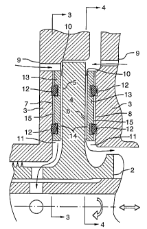
[00010] Figure 1 is an axial cross-sectional view of an
axial thrust air foil bearing with compliant support in
accordance with the invention disposed on two sides of a
rotary flange extending radially from a shaft into a
bearing housing with compressed air flow indicated with
arrows.

[00011] Figure 2 is a detailed axial sectional view
showing the details of the sleeve and rotary flange with
air flow over foils.

[00012] Figure 3 is a radial sectional view along line
3-3 of Figure 2, showing the compliant rings within the
compliant surface of the sleeve.

[00013] Figure 4 is a radial sectional view along line
4-4 of Figure 2, showing the foils within the rotary
flange facing surface of the sleeve.

[00014] Further details of the invention and its
advantages will be apparent from the detailed description
included below.


CA 02509931 2005-06-13
WO 2004/055398 PCT/CA2003/001767
4 -

DETAILED DESCRIPTION OF PREFERRED EMBODIMENTS

[00015] It will be understood that the invention is
applicable to almost any type of engine such as a gas
turbine engine, other motors, generators and

turbochargers.

[00016] Axial thrust bearing 1 bears the axial loads
imposed by engine operation on the shaft 2. Rapid
fluctuations in axial load caused by engine surges for
example,"are accommodated as explained below.

[00017] Figure 1 shows an axial cross-sectional view
through an air foil axial thrust bearing 1 in accordance
with the invention. The axial thrust air bearing 1
transfers axial loads between the shaft 2 and the bearing
housing 3. An annular thrust runner flange 4 extends

radially from the shaft 2 and in the embodiment shown has
a forward runner bearing surface 5 and a rearward runner
bearing surface 6. The housing 3 also has a forward
housing bearing surface 7 and a rearward housing bearing
surface 8.

[00018] Air inlets 9 are in communication with the
source of air such as the compressor ducted from an air
bleed (not shown). Air from the inlets 9 is conducted
over a plurality of foils 10 which in the embodiment
shown are located on the air foil surface of each sleeve
13 facing the abutting surfaces 5, 6 of the flange 4.
[00019] The foils 10 (best seen in Figure 4) create a
cushion of air flowing between the adjacent bearing
surfaces. As shown the foils 10 are formed as
circumferentially spaced apart axially protruding planar

surfaces with radially extending air channels 16 between
adjacent foils 10. The cross-section of the channels 16


CA 02509931 2010-10-21
-

decreases as the air flows downstream. The airfoils 10
are positioned on the runner side of the sleeves 13 to
create a compressed air curtain that serves to lubricate
the boundary between engaging surfaces. A curtain of air
5 is conducted from the inlets 9 over the air foils 10
between the runner bearing surfaces 5, 6 and the facing
sleeve surfaces to the outlets 11 as indicated by arrows
in Figure 2.

[00020] A sleeve 13 with compliant annular rings 12 is
positioned between opposing surfaces of the flange 4 and
bearing housing 3 providing the advantages that load
capacity is increased and damping of axial loading during
engine surges is improved. in addition, tolerances are
increased to accommodate misalignment between components,
parallelism, errors in squareness and waviness of the
bearing surfaces 5-8.

[00021] Of course, creation of a large gap would defeat
the purposes of the foils 10 which require relative close
running gap in order to create a compressed air curtain
in a contained space. The sleeve 13 includes the air
foils 10 with minimal gap between the opposing surfaces.
The sleeve 13 has a foil surface 14 and a compliant
surface 15. In the embodiment shown the compliant
surface 15 and the bearing housing surfaces 7, 8 include
annular grooves for housing two coaxial compliant annular
rings 12. Figure 3 shows the rings 12 mounted in the
grooves of the sleeve 13.

[00022] Depending on the operating temperature of the
bearing, different materials may be utilized for the
compliant annular rings 12 however in all cases the
compliant rings 12 should retain a high degree of


CA 02509931 2005-06-13
WO 2004/055398 PCT/CA2003/001767
6 -

elasticity to accommodate the necessary load damping or
load bearing while maintaining sufficient clearance
between the air foils 10 and runner bearing surfaces 5, 6
for proper operation of the air foil bearing.

[00023] Where operating temperature service is less
than 300 2F a fluorocarbon 0-ring is proposed as a
compliant ring 12. Where operating temperatures are
between 300 2F and 600 F, a fluorosilicon 0-ring can be
used as a compliant ring 12 and where operating

temperatures are in excess of 600 2F, a heat resistant
metallic mesh ring 12 is anticipated.

[00024] In the'embodiment shown the compliant support
includes two annular foil support sleeves 13. However
depending on the load capacity, and loading direction, a

single sleeve 13 or multiple sleeves 13 may be utilized.
Further, in the embodiment shown the inlets 9 are
disposed radially outwardly from the flange 4 and the air
outlets 11 are disposed adjacent to a radially inward
portion of the flange 4 close to the shaft 2. However it

will apparent that depending on availability of
compressed air, air flow may be reversed, i.e. flowing
radially outwardly as opposed to radially inwardly as
shown in Figure 2.

[00025] Although the above description relates to a
specific preferred embodiment as presently contemplated
by the inventors, it will be understood that the
invention in its broad aspect includes mechanical and
functional equivalents of the elements described herein.

Representative Drawing
A single figure which represents the drawing illustrating the invention.
Administrative Status

For a clearer understanding of the status of the application/patent presented on this page, the site Disclaimer , as well as the definitions for Patent , Administrative Status , Maintenance Fee  and Payment History  should be consulted.

Administrative Status

Title Date
Forecasted Issue Date 2011-09-27
(86) PCT Filing Date 2003-11-18
(87) PCT Publication Date 2004-07-01
(85) National Entry 2005-06-13
Examination Requested 2008-09-18
(45) Issued 2011-09-27
Deemed Expired 2013-11-19

Abandonment History

There is no abandonment history.

Payment History

Fee Type Anniversary Year Due Date Amount Paid Paid Date
Registration of a document - section 124 $100.00 2005-06-13
Application Fee $400.00 2005-06-13
Maintenance Fee - Application - New Act 2 2005-11-18 $100.00 2005-09-19
Maintenance Fee - Application - New Act 3 2006-11-20 $100.00 2006-08-23
Maintenance Fee - Application - New Act 4 2007-11-19 $100.00 2007-11-05
Request for Examination $800.00 2008-09-18
Maintenance Fee - Application - New Act 5 2008-11-18 $200.00 2008-09-24
Maintenance Fee - Application - New Act 6 2009-11-18 $200.00 2009-10-23
Maintenance Fee - Application - New Act 7 2010-11-18 $200.00 2010-11-10
Final Fee $300.00 2011-07-12
Maintenance Fee - Application - New Act 8 2011-11-18 $200.00 2011-07-12
Owners on Record

Note: Records showing the ownership history in alphabetical order.

Current Owners on Record
PRATT & WHITNEY CANADA CORP.
Past Owners on Record
BEAUVAIS, GILLES
FOURNIER, YVES
Past Owners that do not appear in the "Owners on Record" listing will appear in other documentation within the application.
Documents

To view selected files, please enter reCAPTCHA code :


To view images, click a link in the Document Description column. To download the documents, select one or more checkboxes in the first column and then click the "Download Selected in PDF format (Zip Archive)" or the "Download Selected as Single PDF" button.

List of published and non-published patent-specific documents on the CPD .

If you have any difficulty accessing content, you can call the Client Service Centre at 1-866-997-1936 or send them an e-mail at CIPO Client Service Centre.


Document
Description 
Date
(yyyy-mm-dd) 
Number of pages   Size of Image (KB) 
Description 2010-10-21 6 248
Abstract 2005-06-13 1 76
Claims 2005-06-13 3 93
Drawings 2005-06-13 3 97
Description 2005-06-13 6 246
Representative Drawing 2005-06-13 1 34
Cover Page 2005-09-09 1 56
Cover Page 2011-08-29 2 64
Representative Drawing 2011-08-29 1 22
Correspondence 2011-07-12 2 64
PCT 2005-06-13 10 369
Assignment 2005-06-13 9 286
Prosecution-Amendment 2008-09-18 2 81
Correspondence 2008-09-18 3 121
Correspondence 2008-10-14 1 16
Correspondence 2008-10-14 1 18
Prosecution-Amendment 2010-05-25 2 40
Prosecution-Amendment 2010-10-21 3 117